EP0496941B1 - Druckausgleichselement für ein wasserdichtes Gehäuse - Google Patents
Druckausgleichselement für ein wasserdichtes Gehäuse Download PDFInfo
- Publication number
- EP0496941B1 EP0496941B1 EP91116178A EP91116178A EP0496941B1 EP 0496941 B1 EP0496941 B1 EP 0496941B1 EP 91116178 A EP91116178 A EP 91116178A EP 91116178 A EP91116178 A EP 91116178A EP 0496941 B1 EP0496941 B1 EP 0496941B1
- Authority
- EP
- European Patent Office
- Prior art keywords
- pressure compensating
- moulded part
- compensating element
- element according
- sealing element
- Prior art date
- Legal status (The legal status is an assumption and is not a legal conclusion. Google has not performed a legal analysis and makes no representation as to the accuracy of the status listed.)
- Expired - Lifetime
Links
- 238000007789 sealing Methods 0.000 claims description 40
- 239000004810 polytetrafluoroethylene Substances 0.000 claims description 5
- 229920001343 polytetrafluoroethylene Polymers 0.000 claims description 5
- 239000013536 elastomeric material Substances 0.000 claims description 3
- 239000002245 particle Substances 0.000 claims description 3
- 239000011148 porous material Substances 0.000 claims description 3
- 238000007493 shaping process Methods 0.000 claims description 2
- 238000005056 compaction Methods 0.000 claims 3
- 238000009434 installation Methods 0.000 claims 1
- 230000002093 peripheral effect Effects 0.000 claims 1
- 230000006835 compression Effects 0.000 description 10
- 238000007906 compression Methods 0.000 description 10
- 238000004519 manufacturing process Methods 0.000 description 4
- 239000007788 liquid Substances 0.000 description 3
- 229920001971 elastomer Polymers 0.000 description 2
- 239000000806 elastomer Substances 0.000 description 2
- 239000012528 membrane Substances 0.000 description 2
- 239000000470 constituent Substances 0.000 description 1
- 230000000694 effects Effects 0.000 description 1
- 239000013013 elastic material Substances 0.000 description 1
- 230000001771 impaired effect Effects 0.000 description 1
- 230000000149 penetrating effect Effects 0.000 description 1
- 238000007711 solidification Methods 0.000 description 1
- 230000008023 solidification Effects 0.000 description 1
- 238000004073 vulcanization Methods 0.000 description 1
- XLYOFNOQVPJJNP-UHFFFAOYSA-N water Substances O XLYOFNOQVPJJNP-UHFFFAOYSA-N 0.000 description 1
Images
Classifications
-
- F—MECHANICAL ENGINEERING; LIGHTING; HEATING; WEAPONS; BLASTING
- F16—ENGINEERING ELEMENTS AND UNITS; GENERAL MEASURES FOR PRODUCING AND MAINTAINING EFFECTIVE FUNCTIONING OF MACHINES OR INSTALLATIONS; THERMAL INSULATION IN GENERAL
- F16J—PISTONS; CYLINDERS; SEALINGS
- F16J3/00—Diaphragms; Bellows; Bellows pistons
- F16J3/02—Diaphragms
-
- H—ELECTRICITY
- H02—GENERATION; CONVERSION OR DISTRIBUTION OF ELECTRIC POWER
- H02B—BOARDS, SUBSTATIONS OR SWITCHING ARRANGEMENTS FOR THE SUPPLY OR DISTRIBUTION OF ELECTRIC POWER
- H02B1/00—Frameworks, boards, panels, desks, casings; Details of substations or switching arrangements
- H02B1/26—Casings; Parts thereof or accessories therefor
- H02B1/28—Casings; Parts thereof or accessories therefor dustproof, splashproof, drip-proof, waterproof or flameproof
-
- H—ELECTRICITY
- H05—ELECTRIC TECHNIQUES NOT OTHERWISE PROVIDED FOR
- H05K—PRINTED CIRCUITS; CASINGS OR CONSTRUCTIONAL DETAILS OF ELECTRIC APPARATUS; MANUFACTURE OF ASSEMBLAGES OF ELECTRICAL COMPONENTS
- H05K5/00—Casings, cabinets or drawers for electric apparatus
- H05K5/02—Details
- H05K5/0213—Venting apertures; Constructional details thereof
- H05K5/0215—Venting apertures; Constructional details thereof with semi-permeable membranes attached to casings
Definitions
- the invention relates to a pressure compensation element for a watertight housing, comprising an inherently strong molded part made of sintered particles of PTFE.
- Such a pressure compensation element is known from FUNKSCHAU 1976, number 18. Then a pressure compensation element made of a PTFE film is provided, which is fastened over the opening of a housing.
- This housing is preferably used to protect electronic circuits from splash water, for example in motor vehicles.
- the pressure compensation element is intended for use on an electrical switching device and is used to compensate for pressure differences between the interior of the switching device and its surroundings.
- the pressure compensation element comprises a one-part or two-part carrier which surrounds the edge of a membrane made of a strip-shaped film on the top and bottom sides in such a way that the membrane is attached to the carrier in a curved manner above.
- the invention has for its object a pressure compensation element further developed in such a way that the areas of the molded part relevant for the function of the pressure compensation element are free of the elastomeric material of the sealing element and that the pressure compensation element is simple and economical to produce.
- the molded part is non-detachably and watertightly fixed to a sealing element made of an elastomeric material that has a sealing surface, which encloses the molded part in the region of its outer circumference, that the molded part is provided with a compression zone radially inside the sealing element, and that the molded part is compressed in the region of the compression zone essentially without pores.
- a sealing element made of an elastomeric material that has a sealing surface, which encloses the molded part in the region of its outer circumference, that the molded part is provided with a compression zone radially inside the sealing element, and that the molded part is compressed in the region of the compression zone essentially without pores.
- the molded part is provided radially inside the sealing element with a compression zone, the molded part being compressed essentially free of pores in the region of the compression zone.
- the compression zone can be limited to the area of at least one circumferential groove. The advantage here is that the liquid elastomer does not penetrate into the entire PTFE body that forms the molded part during the production of the pressure compensation element and thus negatively influences the performance properties. Through the compression zones, the elastomer only penetrates into the area of the molded part and forms a durable and flawless connection with it, which is not relevant for the function of the pressure compensation element. Pore-free compression zones in the form of at least one circumferential groove can be produced simply and economically.
- the groove can have a rounded groove base.
- the advantage here is that the strength of the molded part is significantly increased in the axial direction compared to sharp-edged grooves and thus the service life of the pressure compensation element is extended.
- the molded part can have two mutually opposite grooves.
- the sealing element can be fixed to the molded part during its shaping and solidification.
- the advantage here is that the position of the parts relative to each other is precisely specified, thereby ensuring a perfect connection between the sealing element and the molded part.
- the sealing element can be connected to the molded part by vulcanization.
- the sealing element surrounds the molded part on two opposite sides and that the sealing element can be designed to merge into one another.
- the pressure compensation element is versatile and can be installed in different positions depending on the respective application. For example, it is conceivable that the pressure compensation element is pressed into a circular opening of a housing while the sealing element is pretensioned. In this case, the radial boundary surface of the pressure compensation element seals the interior of the housing from the surroundings.
- the pressure compensation element can, however, also be arranged in the axial direction on a housing surface and can be sealed against it by a prestress in the axial direction. Because the sealing element is designed to merge into one another, it seals well in any case and is easy to produce.
- the sealing element has wavy projections along its radial and axial delimitation, which further increase the sealing effect.
- the molded part and the sealing element can be delimited essentially in a circle.
- the mostly circular housing openings which are particularly economical to manufacture, can due to the elastomeric sealing element that the Encloses molded part, have diameter tolerances without the function of the pressure compensation element being impaired.
- any limits are also conceivable, which can be adapted to the respective application.
- the molded part can be provided with at least two outwardly projecting centering cams which are covered by the sealing element in the region adjacent to the sealing surface.
- the centering cams bring about an exact spatial definition of the molded part with respect to the sealing element in the manufacture of the pressure compensation element. This is particularly advantageous because of the groove-shaped compression zones, for example. It is also advantageous that the spatial definition of the sealing element and the molded part means that the pressure compensation element can have small dimensions both in the radial and in the axial direction.
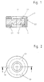
- the pressure compensation element shown comprises an intrinsically strong molded part 1 made of sintered particles of PTFE, which is fixed in a non-detachable and watertight manner to a sealing element 2 made of an elastic material.
- the sealing element 2 surrounds the molded part 1 on two opposite sides in the region of its outer circumference.
- the radial 2.2 and axial sealing surfaces 2.1 of the sealing element 2 are designed to merge into one another.
- the molded part 1 has two mutually opposite grooves 1.1, 1.2, the groove base of which delimits a pore-free compression zone.
- the molded part 1 is provided with centering cams 1.3, which in the area adjacent to the sealing surface are covered by the sealing element 2.
Landscapes
- Engineering & Computer Science (AREA)
- General Engineering & Computer Science (AREA)
- Power Engineering (AREA)
- Mechanical Engineering (AREA)
- Microelectronics & Electronic Packaging (AREA)
- Gasket Seals (AREA)
Applications Claiming Priority (2)
| Application Number | Priority Date | Filing Date | Title |
|---|---|---|---|
| DE4101516A DE4101516C1 (enExample) | 1991-01-19 | 1991-01-19 | |
| DE4101516 | 1991-01-19 |
Publications (2)
| Publication Number | Publication Date |
|---|---|
| EP0496941A1 EP0496941A1 (de) | 1992-08-05 |
| EP0496941B1 true EP0496941B1 (de) | 1995-12-20 |
Family
ID=6423328
Family Applications (1)
| Application Number | Title | Priority Date | Filing Date |
|---|---|---|---|
| EP91116178A Expired - Lifetime EP0496941B1 (de) | 1991-01-19 | 1991-09-24 | Druckausgleichselement für ein wasserdichtes Gehäuse |
Country Status (2)
| Country | Link |
|---|---|
| EP (1) | EP0496941B1 (enExample) |
| DE (2) | DE4101516C1 (enExample) |
Families Citing this family (10)
| Publication number | Priority date | Publication date | Assignee | Title |
|---|---|---|---|---|
| JP2574258Y2 (ja) * | 1993-02-12 | 1998-06-11 | 住友電装株式会社 | 防水筺体 |
| DE29500105U1 (de) * | 1995-01-04 | 1996-05-09 | Feodor Burgmann Dichtungswerke GmbH & Co, 82515 Wolfratshausen | Auftriebselement |
| DE29514362U1 (de) * | 1995-09-07 | 1995-11-16 | Ibs Schillings Gmbh | Elektrische Baugruppe der Schutzart EEx-m |
| DE69935835T2 (de) * | 1998-10-30 | 2007-12-27 | Bridgestone Corp. | Abgedichtete Deckel und deren Herstellungsverfahren |
| DE10012297C2 (de) * | 2000-03-14 | 2002-02-07 | Bosch Gmbh Robert | Gehäuse für ein elektrisches Gerät |
| DE102005047662B4 (de) * | 2005-09-22 | 2012-02-16 | Axel R. Hidde | Druckausgleichsverschraubung mit Druckausgleichselement |
| DE102008033974A1 (de) * | 2008-07-21 | 2010-01-28 | Giesecke & Devrient Gmbh | Sensor für die Prüfung von Wertdokumenten |
| DE202010006041U1 (de) | 2010-04-19 | 2010-07-22 | Hidde, Axel R., Dr. | Dichtring mit Membranventil |
| DE102013216718A1 (de) | 2013-08-22 | 2015-02-26 | Continental Automotive Gmbh | Aufprallsensor mit elastisch deformierbarem Schlauch und Drucksensor und zweistufigem Druckausgleich |
| DE102018221202A1 (de) * | 2018-12-07 | 2020-06-10 | Bühler Motor GmbH | Elektrischer Antrieb |
Family Cites Families (2)
| Publication number | Priority date | Publication date | Assignee | Title |
|---|---|---|---|---|
| FR2573948B1 (fr) * | 1984-11-29 | 1987-02-20 | Bendix Electronics Sa | Dispositif echangeur pour boitier electronique |
| FR2637763B1 (fr) * | 1988-10-12 | 1992-09-11 | Bosch Gmbh Robert | Element d'equilibrage de pression pour des dispositifs electriques |
-
1991
- 1991-01-19 DE DE4101516A patent/DE4101516C1/de not_active Expired - Lifetime
- 1991-09-24 EP EP91116178A patent/EP0496941B1/de not_active Expired - Lifetime
- 1991-09-24 DE DE59107122T patent/DE59107122D1/de not_active Expired - Lifetime
Also Published As
| Publication number | Publication date |
|---|---|
| EP0496941A1 (de) | 1992-08-05 |
| DE4101516C1 (enExample) | 1991-08-01 |
| DE59107122D1 (de) | 1996-02-01 |
Similar Documents
| Publication | Publication Date | Title |
|---|---|---|
| EP0897317B1 (de) | Endscheibe für ein ringfilterelement mit radial wirkender dichtung | |
| EP0179995B1 (de) | Dichtung | |
| DE3685800T2 (de) | Fluidumfilter und dessen fluidumdichte befestigung. | |
| DE3631620C2 (de) | Elastische, mit einer Flüssigkeit gefüllte Buchse | |
| DE3524461C2 (enExample) | ||
| DE10246354B4 (de) | Gleichlaufgelenkmanschette | |
| EP0033964A2 (de) | Radialwellendichtring | |
| DE112007001672B4 (de) | Aktuator | |
| DE10036740B4 (de) | Schwingungsdämpfungseinrichtung, deren elastischer Körper eine gute Haltbarkeit aufweist | |
| EP0496941B1 (de) | Druckausgleichselement für ein wasserdichtes Gehäuse | |
| EP1995088A2 (de) | Einsatzlagerteil, elastisches Einsatzlager und Federbeinlageranordnung | |
| DE3827326C2 (enExample) | ||
| EP4004413B1 (de) | Drehschieberventil für einen kühlkreislauf | |
| EP1612066A1 (de) | Ringscheibe für ein Gleitlager | |
| EP0317903B1 (de) | Dichtring | |
| EP0611892B1 (de) | Bundzapfengelenk | |
| DE3903780C2 (de) | Dichtring | |
| DE3612420C2 (enExample) | ||
| WO2004090299A1 (de) | Dichtungselement für eine kühlmodulanordnung eines kraftfahrzeuges und kühlmodulanordnung mit einem solchen dichtungselement | |
| EP0863334B1 (de) | Faltenbalg | |
| DE19954857A9 (de) | Befestigungsvorrichtung für eine Zusatzmatte | |
| DE112009002234B4 (de) | Balg umfassend einen Befestigungsbereich mit mindestens zwei umlaufenden äußeren Rippen | |
| DE60000640T2 (de) | Bürstenhaltermontage für elektrische maschinen wie kfz-anlasser | |
| DE2546805C3 (de) | Dichtring für drehbare Körper, wie Wellen o.dgl. | |
| DE102017209890A1 (de) | Kugelgelenk für einen Zweipunktlenker sowie Zweipunktlenker mit einem solchen Kugelgelenk |
Legal Events
| Date | Code | Title | Description |
|---|---|---|---|
| PUAI | Public reference made under article 153(3) epc to a published international application that has entered the european phase |
Free format text: ORIGINAL CODE: 0009012 |
|
| 17P | Request for examination filed |
Effective date: 19920529 |
|
| AK | Designated contracting states |
Kind code of ref document: A1 Designated state(s): DE FR GB IT |
|
| RAP3 | Party data changed (applicant data changed or rights of an application transferred) |
Owner name: FIRMA CARL FREUDENBERG |
|
| 17Q | First examination report despatched |
Effective date: 19941110 |
|
| GRAA | (expected) grant |
Free format text: ORIGINAL CODE: 0009210 |
|
| AK | Designated contracting states |
Kind code of ref document: B1 Designated state(s): DE FR GB IT |
|
| REF | Corresponds to: |
Ref document number: 59107122 Country of ref document: DE Date of ref document: 19960201 |
|
| ITF | It: translation for a ep patent filed | ||
| GBT | Gb: translation of ep patent filed (gb section 77(6)(a)/1977) |
Effective date: 19960122 |
|
| ET | Fr: translation filed | ||
| PGFP | Annual fee paid to national office [announced via postgrant information from national office to epo] |
Ref country code: FR Payment date: 19960820 Year of fee payment: 6 |
|
| PGFP | Annual fee paid to national office [announced via postgrant information from national office to epo] |
Ref country code: GB Payment date: 19960903 Year of fee payment: 6 |
|
| PGFP | Annual fee paid to national office [announced via postgrant information from national office to epo] |
Ref country code: DE Payment date: 19960905 Year of fee payment: 6 |
|
| PLBE | No opposition filed within time limit |
Free format text: ORIGINAL CODE: 0009261 |
|
| STAA | Information on the status of an ep patent application or granted ep patent |
Free format text: STATUS: NO OPPOSITION FILED WITHIN TIME LIMIT |
|
| 26N | No opposition filed | ||
| PG25 | Lapsed in a contracting state [announced via postgrant information from national office to epo] |
Ref country code: DE Effective date: 19970718 |
|
| PG25 | Lapsed in a contracting state [announced via postgrant information from national office to epo] |
Ref country code: GB Free format text: LAPSE BECAUSE OF NON-PAYMENT OF DUE FEES Effective date: 19970924 |
|
| PG25 | Lapsed in a contracting state [announced via postgrant information from national office to epo] |
Ref country code: FR Free format text: THE PATENT HAS BEEN ANNULLED BY A DECISION OF A NATIONAL AUTHORITY Effective date: 19970930 |
|
| GBPC | Gb: european patent ceased through non-payment of renewal fee |
Effective date: 19970924 |
|
| REG | Reference to a national code |
Ref country code: FR Ref legal event code: ST |
|
| PG25 | Lapsed in a contracting state [announced via postgrant information from national office to epo] |
Ref country code: IT Free format text: LAPSE BECAUSE OF NON-PAYMENT OF DUE FEES;WARNING: LAPSES OF ITALIAN PATENTS WITH EFFECTIVE DATE BEFORE 2007 MAY HAVE OCCURRED AT ANY TIME BEFORE 2007. THE CORRECT EFFECTIVE DATE MAY BE DIFFERENT FROM THE ONE RECORDED. Effective date: 20050924 |