EP0496677B1 - Egaliseurs adaptatifs - Google Patents
Egaliseurs adaptatifs Download PDFInfo
- Publication number
- EP0496677B1 EP0496677B1 EP92400175A EP92400175A EP0496677B1 EP 0496677 B1 EP0496677 B1 EP 0496677B1 EP 92400175 A EP92400175 A EP 92400175A EP 92400175 A EP92400175 A EP 92400175A EP 0496677 B1 EP0496677 B1 EP 0496677B1
- Authority
- EP
- European Patent Office
- Prior art keywords
- equalizing
- signal
- equalized
- characteristic
- characteristic detection
- Prior art date
- Legal status (The legal status is an assumption and is not a legal conclusion. Google has not performed a legal analysis and makes no representation as to the accuracy of the status listed.)
- Expired - Lifetime
Links
Images


Classifications
-
- H—ELECTRICITY
- H04—ELECTRIC COMMUNICATION TECHNIQUE
- H04L—TRANSMISSION OF DIGITAL INFORMATION, e.g. TELEGRAPHIC COMMUNICATION
- H04L25/00—Baseband systems
- H04L25/02—Details ; arrangements for supplying electrical power along data transmission lines
- H04L25/03—Shaping networks in transmitter or receiver, e.g. adaptive shaping networks
- H04L25/03006—Arrangements for removing intersymbol interference
- H04L25/03165—Arrangements for removing intersymbol interference using neural networks
-
- H—ELECTRICITY
- H04—ELECTRIC COMMUNICATION TECHNIQUE
- H04L—TRANSMISSION OF DIGITAL INFORMATION, e.g. TELEGRAPHIC COMMUNICATION
- H04L25/00—Baseband systems
- H04L25/02—Details ; arrangements for supplying electrical power along data transmission lines
- H04L25/03—Shaping networks in transmitter or receiver, e.g. adaptive shaping networks
- H04L25/03006—Arrangements for removing intersymbol interference
- H04L2025/03433—Arrangements for removing intersymbol interference characterised by equaliser structure
- H04L2025/03439—Fixed structures
- H04L2025/03445—Time domain
- H04L2025/03464—Neural networks
Definitions
- the present invention relates to equalizers for compensating deterioration of signals over transmission lines of communication systems, and in particular, to adaptive equalizers for detecting characteristics of transmission lines in radio and cable communications and for equalizing received signals by using the detected results.
- an adaptive equalizing technique for adaptively equalizing deterioration of a signal over a transmission line in accordance with time-by-time variation of characteristics should be established.
- a conventional radio transmission line comprises a radio device and a transmission line.
- the radio device further comprises a transmission filter, a reception filter, a modulator, a demodulator, a transmitter, and a receiver.
- the characteristics of the transmission line vary depending on weather conditions, buildings, and so forth between the transmitter and the receiver.
- causes of signal deterioration include linear and nonlinear distortion generated from constructional devices of the system and two-wave interfered fading generated from the transmission line as linear distortion.
- the distortion generated from devices for mobile radio communication is stable with respect to time, the distortion of a propagation path generated over the transmission line between the mobile station and the ground station becomes selective fading which varies with time.
- the distortion of the signals over the transmission line should be adaptively equalized.
- Fig. 1A is a schematic showing the concept of a mobile communication.
- a mobile communication is performed between a mobile station 1 and a ground station 2.
- the direct wave is directly propagated between the mobile station 1 and the ground station 2.
- the reflected wave is reflected by an obstacle 3 such as a building, a mountain, ground, or the like.
- an obstacle 3 such as a building, a mountain, ground, or the like.
- fading occurs between the direct wave and the reflected wave.
- the amplitude ratio, propagation delay time, and phase difference between the direct wave and the reflected wave rapidly vary.
- the deterioration of the signals should be adaptively and rapidly equalized in accordance with this variation.
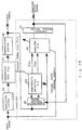
- Fig. 1B is a block diagram showing a construction of a transversal type equalizer of an equalizer as a related art.
- the transversal type equalizer demodulates a received signal supplied from the transmission line by using a demodulator 4. Thereafter, the demodulated signal is successively set to a tapped delay line 5.
- Each coefficient adjustment device 7 multiplies an output of each delay device 6 by a coefficient.
- An adder 8 adds output signals from the coefficient adjustment devices 7 and outputs the result.
- the conventional transversal type equalizer shown in Fig. 1B is effective against linear distortion. However, when nonlinear distortion occurs over a transmission line or when a nonlinear circuit is used in a demodulation system, received signals are not properly equalized.
- an object of the present invention is to provide a function for detecting characteristics of a transmission line and equalizing a signal by using the detected result and thereby adaptively equalizing both linear and nonlinear distortions of the signal.
- a feature of the present invention resides in an adaptive equalizer, comprising characteristic detection means for detecting a characteristic of an object to be equalized by using an output signal corresponding to a known input signal of said object to be equalized, so that a deterioration of the output signal is compensated; and equalizing means for equalizing an output signal of said object to be equalized in accordance with an unknown input signal by using the detected result of said characteristic detection means, characterized in that said adaptive equalizer further comprises a characteristic detection control device, disposed in the preceding stage of said characteristic detection means, for supplying, during a training phase, said known input signal and an output signal of said object to be equalized to said characteristic detection means while said known input signal is inputted to said object to be equalized and for supplying, after the training phase, an output signal of said equalizing means as a signal instead of said known input signal and an output signal of said object to be equalized to said characteristic detection means while an unknown input signal is inputted to said object to be equalized after said known input signal is inputted, thereby successively detecting
- Figs. 2 to 5 are block diagrams for explaining theories of the present inventions. These figures are block diagrams of adaptive equalizers for detecting characteristics of an object to be equalized where a known input signal is inputted and for compensating the output signal.
- the object to be equalized is for example a transmission line.
- Fig. 2 is a block diagram for explaining a theory of the first and third inventions.
- a characteristic detection means 11 detects characteristics such as a transfer function of an object to be equalized 10, for example a transmission line, which is to be equalized to compensate deterioration of an output signal in accordance with a known input signal.
- An equalizing means 12 equalizes an output signal of the object to be equalized 10 in accordance with an unknown input signal by using the detected result of the characteristic detection means 11.
- Fig. 3 is a block diagram for explaining a theory of the second invention.
- a characteristic detection means 11 detects characteristics of an object to be equalized 10 in the same manner as in the first invention.
- An equalizing control means 14 uses the detected result of the characteristic detection means 11 and outputs a control signal for equalizing an output signal of the object to be equalized 10 in accordance with an unknown input signal.
- An equalizing means 15 equalizes an output signal of the object to be equalized 10 in accordance with an unknown input signal in accordance with an output signal of the equalizing control means 14.
- the equalizing means 15 comprises for example a plurality of equalizing circuits and a weighting addition circuit for weighting and adding the output signals of the equalizing circuit.
- the equalizing control means 14 outputs a weight signal in accordance with each output signal of the plurality of equalizing circuits. Thus, the output signals of the plurality of equalizing circuits are weighted and the sum thereof is outputted as an equalized output signal.
- the characteristic detection means 11 is for example a neural network.
- the characteristic detection means 11 detects characteristics such as a transfer function of the object to be equalized 10, for example, a transmission line, which is to be equalized to compensate for deterioration of an output signal, by using an output signal in accordance with a known input signal of the object to be equalized 10.
- values of the internal state of the neural network as the characteristic detection means 11, for example the weight of internal linkage are constant regardless of the signal pattern of the known input signal.
- the weight of the internal linkage is switched in accordance with the signal pattern of the known input signal.
- a calculation means 12 equalizes an output signal of the object to be equalized 10 in accordance with an unknown input signal by using the detected result of the characteristic detection means 11 and outputs an equalized output signal.
- Fig. 4 is a block diagram for explaining the theory of the fourth invention.
- a characteristic detection means 11 is for example a neural network, as in the third invention.
- the characteristic detection means 11 detects characteristics of an object to be equalized 10.
- the weight as an internal state value of the neural network is not switched in accordance with the signal pattern of an input signal. The characteristics are detected while the weight of the internal linkage is not changed.
- a post-process means 16 successively stores the result detected by the characteristic detection means 11 by using output signals of an object to be equalized 10 which are outputted in a time series manner and performs a post-process on the detected result of the characteristics being stored, for example, an average value of transfer functions.
- the post-process means 16 is constructed of for example a shift register and a neural network.
- An equalizing means 17 equalizes an output signal of the object to be equalized 10 by using an output signal of the post-process means 16 as the detected result of the characteristics of the object to be equalized 10.
- the equalizing means 17 is also constructed of for example a neural network.
- Fig. 5 is a block diagram for explaining the theory of the fifth invention.
- the operations of a characteristic detection means 11 and an equalizing means 12 of the fifth invention are the same as those of the first invention.
- An equalizing error detection and learning pattern storage means 18 compares a known input signal of an object to be equalized 10 with an output signal of an equalizing means 12. When this storage means 18 detects an equalizing error, it stores the output signal, the detected result of a characteristic detection means 11 and a known input signal, which is a correct output signal of the object to be equalized 10, as a learning pattern.
- a learning control means 19 causes the equalizing means 12, for example a neural network, to learn by using a learning pattern stored in the equalizing error detection and learning pattern storage means 18 while the object to be equalized 10 is not outputting a signal, for example, while the transmission line as the object to be equalized 10 is not being used.
- a known bit train named a training sequence or a recognition signal is placed at the beginning of a packet.
- This bit train is used as a known input signal for detecting characteristics of the object to be equalized 10, for example the transmission line.
- the characteristic detection means 11 for example the neural network, detects the characteristics of the transmission line, for example the real part and the imaginary part of a transfer function thereof.
- the equalizing means 12 equalizes an output signal of the transmission line in accordance with an unknown input signal.
- the equalizing means 12 is also formed of for example a neural network.
- a control signal for equalizing an output signal of an object to be equalized 10 in accordance with an unknown input signal is outputted.
- This control signal is a weight signal for each output signal of part of an equalizing means 15, for example a plurality of equalizing circuits. The weighted results of output signals of the plurality of equalizing circuits are added and outputted as an equalized output signal.
- Each equalizing circuit is also constructed of a neural network.
- a neural network as a characteristic detection means 11 switches a known input signal, which is the weight of the neural network as a characteristic detection parameter, in accordance with a bit pattern of a training sequence and detects the real part and the imaginary-part part of a transfer function. Thereby, an output signal of the transmission line in accordance with an unknown input signal is equalized.
- a bit train of a training sequence is shifted for example bit by bit and input to a characteristic detection means 11.
- the detected result of each bit train is stored in, for example, a shift register.
- a post-process for example an average process, is performed.
- an output signal of the object to be equalized 10 is equalized in accordance with an unknown input signal.
- a characteristic detection means 11 detects characteristics of an object to be equalized 10. By using the detected result, an output signal of the object to be equalized 10 is equalized in accordance with an unknown input signal.
- an equalizing error detection and learning pattern storage means 18 compares a known input signal of an object to be equalized 10 with an output signal of an equalizing means 12.
- the storage means 18 detects an equalizing error, it stores the output signal, the detected result of the characteristic detection means 11, and a correct output signal of the object to be equalized 10 as a learning pattern. For example, while no communication takes place on the transmission line, the equalizing means 12 performs a learning process by using this learning pattern.
- a training sequence placed at the beginning of a packet is used as the known input signal of the object to be equalized 10.
- the characteristics of the transmission line may vary.
- a characteristic detection control device is provided in the preceding stage of a characteristic detection means 11 as shown in Figs. 2 to 5 (the first to fifth inventions).
- the characteristic detection control device supplies a known input signal and an output signal of an object to be equalized 10 to a characteristic detection means 11 while a training sequence as a known input signal is inputted to the object to be equalized 10. After the input of the training sequence is completed, while an unknown input signal, i.e., transmission data is being inputted to the object to be equalized 10, the characteristic detection control device supplies both an output signal of the equalizing means 12 as a signal instead of the known input signal and an output signal of the object to be equalized 10 to the characteristic detection means 11. Thereby, the characteristic detection means 11 continuously detects the characteristics.
- an output signal can be equalized in accordance with the transfer characteristics which vary each time.
- Fig. 6 is a block diagram showing a construction of an adaptive equalizer in accordance with the first invention.
- the adaptive equalizer 20 comprises a characteristic detection device 22 for detecting a transfer characteristic, for example, transfer function H ( ⁇ ) of an object to be equalized 21; and an equalizing device 23 for equalizing an output signal of the object to be equalized 21 by using the transfer function characteristic being detected.
- a characteristic detection device 22 for detecting a transfer characteristic, for example, transfer function H ( ⁇ ) of an object to be equalized 21
- an equalizing device 23 for equalizing an output signal of the object to be equalized 21 by using the transfer function characteristic being detected.
- the characteristic detection device 22 and the equalizing device 23 are for example neural networks.
- the characteristic detection device 22 learns the transfer function of the object to be equalized 21 as a teacher signal.
- the equalizing device 23 learns an input signal of the object to be equalized 21 as a teacher signal.
- Fig. 7A is a block diagram showing the construction of an embodiment of the adaptive equalizer in accordance with the first invention.
- the object to be equalized 21 of Fig. 6 comprises a modulation system 26, a propagation path 27, and a demodulation system 28.
- the adaptive equalizer 25 comprises an input pattern generation portion 24, which will be described later in detail; a characteristic detection neural network 29, which is equivalent to the characteristic detection device 22 of Fig. 5; an equalizing neural network 30, which is equivalent to the equalizing device 23 thereof; and a threshold process portion 31.
- the characteristic detection neural network 29 detects real part X ( ⁇ ) and imaginary part Y ( ⁇ ) of each transfer function of the overall system comprising the modulation system 26, the propagation path 27, and the demodulation system 28 (hereinafter, the overall system is named the transmission line) by using known digital signals which are an input signal of the characteristic detection neural network 29 and a demodulation signal of the demodulation system 28 in accordance with the input signal, namely the output signal thereof.
- the equalizing neural network 30 equalizes the demodulation signal which is outputted from the demodulation system 28 by using the detected result.
- the threshold process portion 31 converts the equalized result into digital data of 0's and 1's in accordance with a proper threshold value and outputs the resultant data as a digital signal which is an equalized output signal.
- Fig. 7B shows a model of the propagation path 27 of Fig. 7A.
- the propagation path is described as an interfered fading model of two waves: a direct wave and a reflected wave.
- the transfer function of this transmission line can be expressed by the following equations.
- the transfer function of the modulation system 26 and that of the demodulation system 28 are offset, it is possible to consider the transfer function of the propagation path 27 as that of the entire transmission line.
- ⁇ , ⁇ ', and ⁇ ' are obtained by using the original ⁇ , ⁇ , and ⁇ . Thereafter, by using equations (4) and (5), the real part and the imaginary part of the transfer function can be calculated.
- the characteristic detection neural network 29 detects the transfer function, the phase difference of the reflected wave and the direct wave over the transmission line and the amplitude ratio thereof are obtained as characteristics.
- Fig. 8 is a block diagram showing the construction of the modulation system 26 in accordance with the embodiment of Fig. 7A.
- the signal of the I channel is equivalent to a detector output where a carrier component obtained from a received wave is used as a reference signal in for example demodulation state and the signal of the Q channel is equivalent to a detector output of a signal that the phase of a carrier component is advanced by ⁇ /2.
- Fig. 9 is a block diagram showing the construction of the demodulation system 28 of Fig. 7A.
- This demodulation system restores the received signal by using a detection means such as synchronous detection or delay detection.
- BPF is a band pass filter
- LPF is a low pass filter
- AD is an AD converter.
- the demodulation system 28 quadruply oversamples the received analog signal and converts the signal into a digital signal.
- Fig. 10 is a packet format of data transmitted over a transmission line of an embodiment of the present inventions.
- a known bit train consisting of for example 16 bits is placed.
- This bit train is named a training sequence.
- An information portion is data which is really transmitted. Since this embodiment relates to a digital mobile phone system, signals for use are constructed of binary values of 0's and 1's.
- a SYNC word and a guard are special codes representing the beginning and the end of each packet, respectively.
- Fig. 11 is a schematic showing a characteristic detection neural network 29 of an embodiment of the adaptive equalizer of Fig. 7A.
- the characteristic detection neural network 29 is a three-layered neural network where each layer is fully linked.
- a really received signal is inputted to 16 input units as an output signal of the demodulation system 28.
- a bit train of the training sequence shown in Fig. 7 is inputted to the remaining 16 input units as an ideal output value.
- the bit train of the training sequence at the beginning of each packet and the bit train of the received signal are inputted to each unit of the input layer through a delay device D (shift register) of both the I and Q channels, each bit train consisting of eight bits.
- the characteristic detection neural network compares the known training sequence with the really received signal.
- the characteristic detection neural network detects the transfer function of the transmission line and outputs the real part X ( ⁇ ) and the imaginary part Y ( ⁇ ) thereof.
- Fig. 12 is a block diagram showing the construction of an embodiment of an input pattern generation portion in the characteristic detection neural network.
- the input pattern generation portion comprises a training sequence detection portion 36 for detecting a training sequence of a packet from a received signal; a training sequence memory 37 for storing a bit train of a training sequence; and a synchronizing device 38 for synchronizing a received signal with an ideal value stored in the training sequence memory 37 in accordance with an output signal of the training sequence detection portion 36 and outputting the resultant signal to the characteristic detection neural network 39.
- Fig. 13 is a block diagram showing the construction of the training sequence detection portion 36 of the input pattern generation portion.
- the training sequence detection portion detects the timings of the beginning and the end of the training sequence.
- a frame synchronizing device 36a establishes the synchronization of a packet by using a received signal and outputs a reset signal to a counter 36b. With this reset signal, the counter 36b outputs the training sequence timing signal which represents the timings of the beginning and the end of the training sequence of each packet.
- a signal with a strong auto correlation is followed by a packet.
- the frame synchronization is established. Since this means is out of the scope of the present invention, the description thereof is omitted in this specification.
- Fig. 14 is a block diagram showing the construction of the training sequence memory of the input pattern generation portion.
- the training sequence memory 37 comprises a counter 37a for inputting a training sequence timing signal which is sent from the training sequence detection portion 36 through the synchronizing device 38; and a memory 37b for storing data of the training sequence and, memory 37b from which the stored data is read as an ideal value under the control of the counter 37a.
- Fig. 15 is a schematic showing an example of input signals of the characteristic detection neural network of Fig. 11.
- the figure shows waveforms of ideal signals and demodulated signals which are actually outputted from the demodulation system 28 on both the I and Q channels.
- the demodulation system 28 quadruply oversamples one symbol of the original digital signal. Data of eight points for two symbols of ideal values and original digital signals on both the I and Q channels are inputted to the characteristic detection neural network. Thus, the number of input data pieces becomes 32.
- the characteristic detection neural network shown in Fig. 11 detects the transfer function of a transmission line, it is necessary to cause the neural network to learn in advance.
- This learning process is performed by using values of the real part X ( ⁇ ) and the imaginary part y ( ⁇ ) of the transfer function of the transmission line as a teacher signal by means of for example back-propagation method.
- the learning data generation methods are categorized as a first method where computer software for simulating a modulation system, a transmission line, and a demodulation system are created on a computer and then a simulation is executed; and a second method where hardware of modulation and demodulation systems and hardware for simulating the operation of a transmission line model are created and data is experimentally obtained.
- the first method using computer simulation is used.
- Fig. 16 is a table showing variation of transmission line parameters in the above simulation.
- the figure shows variation of ⁇ , ⁇ ', and ⁇ ' in equations (4) and (5).
- ⁇ 0, since the effect of a reflected wave can be ignored, there are 25 combinations of ⁇ , ⁇ ', and ⁇ ' of learning data.
- a 1-bit earlier signal value affects the demodulated waveform due to the effect of the reflected wave, all patterns where the bit is varied are generated.
- Fig. 17 is a schematic for describing the necessity to learn all combinations of 3 bits on each channel of I and Q.
- the delay of the reflected wave corresponding to the direct wave is up to 1 bit.
- the figure also shows digital signals corresponding to the direct wave and the reflected wave where there is a delay of 1 bit.
- a received signal of 2 bits is quadruply oversampled on each I and Q channel and then inputted to the characteristic detection neural network.
- the received signal of 2 bits is affected by the 1 bit that precedes it.
- Fig. 20 shows an embodiment of the equalizing neural network 30 of Fig. 6.
- the equalizing neural network is a three-layered hierarchical neural network where each layer is fully linked.
- the equalizing neural network equalizes an output signal of a demodulation system by a nonlinear process of a neural network so as to remove nonlinear distortions of the transmission line and the demodulation system and to equalize the output signal of the demodulation system to a predetermined value.
- An output signal of the demodulation system is sent to a low pass filter and then oversampled at a period four times higher than the signal period. Thereafter, the resultant signal is A/D converted and then inputted to each unit in the input layer of the equalizing neural network.
- the values of the real part and the imaginary part of the transfer function as the transmission line characteristics are inputted. By using these characteristics, the received signal is equalized.
- Fig. 20 there are 18 units in the input layer of the equalizing neural network where 16 units are used for inputting a received signal and two units are used for inputting values of the real part and imaginary part of the transfer function.
- the output layer has two output units in accordance with the I and Q channels.
- the intermediate layer has 12 units which are experimentally determined.
- the equalizing neural network outputs an ideal center value by using 2-bit data which are quadruply oversampled. Whenever the demodulated signal is sampled, it is shifted and inputted to the equalizing neural network. In addition, whenever the received signal is sampled, the equalized result is continuously outputted. Thus, the data amount of the output signal of each channel of I and Q becomes 1 bit.
- Fig. 21 is a schematic describing a control system for inputting data to an equalizing neural network.
- a latch circuit 400 not shown in Fig. 7A, is provided between the characteristic detection neural network 29 and the equalizing neural network 30.
- the above mentioned training sequence detection portion 36 outputs a latch reset signal to the latch circuit 400.
- the training sequence detection portion 36 can be used in common with the training sequence detection portion of the input pattern generation portion of Fig. 12.
- Fig. 22 is a timing chart showing an embodiment of the equalizing neural network of the circuit of Fig. 21. Since the timing chart of the I channel is the same as that of the Q channel, the timing chart of one channel is described.
- the first 8 bits of the received signal represent the output result of the transmission line in accordance with the training sequence of one channel.
- the "Information" represents the output result of the transmission line in accordance with unknown input information that follows.
- the latch circuit 400 is reset with a reset signal from the training sequence detection portion 36.
- the received signal is thereby inputted to the characteristic detection neural network 29.
- the characteristic detection neural network 29 receives 8-bit data quadruply oversampled, which are 2-bit data of the received data in accordance with the training sequence, it outputs the detected characteristics.
- the result is then latched by the latch circuit 400.
- the equalizing neural network 30 is activated.
- the received signal in accordance with the training sequence is thereby equalized.
- the output signal is equalized in accordance with the unknown input information.
- Figs. 21 and 22 the operation of the equalizing neural network is described assuming that 2-bit data of the training sequence of one channel are used. However, when the characteristics are detected by using more bits of the training sequence, as shown in Fig. 23, to compensate for delay in operation of the characteristic detection neural network 29, the received signal is inputted to the equalizing neural network 30 through a delay device 401.
- Fig. 24 shows an example of a learning of data of the equalizing neural network.
- Fig. 24 (a) shows transmission line parameters for learning data of the characteristic detection neural network.
- the transmission line parameters are data generated in accordance with the parameters of Fig. 16.
- the values of the real part X and the imaginary part Y of the transfer function are theoretical values obtained from the above equations rather than real output values of the characteristic detection neural network.
- the teacher signal uses the value at the middle of 8 points, namely, the value between the fourth and fifth points, in accordance with 2-symbol digital data as shown in Fig. 24 (b). In other words, to compensate for a delay of one bit, data of 2 bits are inputted and the middle portion thereof is used as the teacher signal. The performance is not remarkably affected by the selection of the fourth point or the fifth point.
- Fig. 25 is a flow chart of an embodiment of the output signal equalizing process in accordance with the first invention.
- step (S) 40 a training sequence of a packet is detected.
- the bit train of the training sequence and the received signal are set to each input unit of the characteristic detection neural network at S41.
- S42 the real part X and the imaginary part Y of the transfer function are detected as the characteristics of the transmission line.
- the detected characteristic is set to each input unit of the equalizing neural network.
- the demodulated signal is set to each input unit of the equalizing neural network.
- the equalizing neural network outputs an equalizing signal.
- the threshold process portion 31 shown in Fig. 3 processes the threshold value of the signal and outputs a resultant digital signal. Thereafter, the steps of S44 or later are repeated.
- the process returns to S40. At this step, the process following the detection of the training sequence in accordance with the next packet is repeated.
- FIG. 26 shows sampling points for use in the experiment.
- An output signal of the equalizing neural network is sampled at sampling points shown in the figure and then converted into digital data by using a threshold value of 0.5.
- Fig. 27 shows a bit error rate of the experimental result.
- "Learning” represents the bit error rate where learning data is equalized in accordance with the present embodiment
- "Unknown” represents the bit error rate where unknown data is equalized
- “Not equalized” represents the bit error rate where a received signal is sampled at sampling points shown in Fig. 26 and the threshold process of the signal is performed without the adaptive equalizer in accordance with the present invention.
- the characteristic detection neural network detects characteristics of a transmission line, for example, a transfer function, by using the first 4 bits (2 bits for each channel of I and Q) of the training sequence at the beginning of a packet. Thereafter, by using the detected result, the equalizing neural network equalizes the remaining portion of the packet, which is an output signal, in accordance with the information portion.
- a feedback type adaptive equalizer is used.
- the equalizer treats an equalized output signal, which is output by the equalizing neural network, as a correct input signal, namely a known input signal, after the signal in accordance with the training sequence is received.
- the feedback type adaptive equalizer can continue to detect characteristics even after the signal is received.
- Fig. 28 is a block diagram showing the construction of an embodiment of the feedback type adaptive equalizer.
- a characteristic detection control device 48 which is a neural network, instead of the input pattern generation portion 24.
- the characteristic detection control device 48 controls the characteristic detection process of the characteristic detection neural network.
- Fig. 29 is a block diagram showing the construction of an embodiment of the characteristic detection control device.
- the characteristic detection control device 48 comprises a received signal synchronizing device 48a for synchronizing a received signal with an ideal value and outputting the received signal to the characteristic detection neural network, a training sequence detection portion 48b for detecting a training sequence from the received signal, and an ideal value control device 48c for outputting an ideal value to the characteristic detection neural network.
- the received signal synchronizing device 48a comprises a received signal FIFO 48d for delaying a received signal by 1 bit and an oversampled signal by 4 bits, and a received signal selector 48e for selecting the received signal or the output signal of the received signal FIFO 48d.
- the ideal value control device 48c comprises a training sequence memory 48f for storing a training sequence, and an ideal value selector 48g for selecting an output signal of the training sequence memory 48f or an equalized output signal and outputting the selected signal.
- the training sequence detection portion 48b and the training sequence memory 48f of Fig. 29 are the same as those of Figs. 13 and 14.
- Fig. 30 is a block diagram showing the construction of the received signal FIFO 48d of Fig. 29.
- a received signal quadruply oversampled is inputted to the received signal FIFO 48d.
- the FIFO 48d inputs a quadruply oversampled signal and outputs it to the received signal selector 48e through four delay devices having a 1/4 delay period of one bit of the received signal. Then, with reference to Figs. 29 and 30, the characteristic detection of Fig. 28 is described.
- the training sequence detection portion 48b detects the timings of the beginning and the end of a training sequence and then outputs them to the received signal synchronizing device 48a and the ideal value control device 48c.
- the received signal selector 48e outputs the received signal by using a timing signal.
- the ideal value selector 48g selects the training sequence from the training sequence memory 48f and outputs it.
- the characteristic detection neural network treats the training sequence as a known input signal and detects the characteristics of the transmission line.
- the timing signal is outputted once again.
- the received signal selector 48e selects the output signal of the received signal FIFO 48d
- the ideal value selector 48g selects the equalized output signal of the equalizing neural network and outputs the signal to the characteristic detection neural network 29.
- the delay period of the equalizing operation of the equalizing neural network is one bit of the signal.
- the received signal FIFO 48d delays the received signal by 1 bit.
- the delayed signal is outputted to both the equalizing neural network and the characteristic detection neural network 29.
- the characteristic detection neural network continues to detect the characteristics of the transmission line by using the equalized output signal instead of the known input signal.
- the delay period of the received signal FIFO of Fig. 30 is adjusted in accordance with the delay period of the equalizing neural network.
- Fig. 31 is a timing chart of a signal equalizing process in accordance with the embodiment of Fig. 28.
- Fig. 31 (a) shows an example of a received signal where the first shadowed portion, or portion from period 0 to period 7, is a training sequence and the portion that follows is an unknown input signal, or a received signal in accordance with the data.
- the received signal is an analog signal, in the figure it is treated as a corresponding digital signal.
- a received signal is quadruply oversampled and then inputted to the adaptive equalizer.
- periods of Fig. 31 (a) are divided into four portions.
- period 0 is represented by portions 0.0 to 0.3.
- 2 bits of a received signal for each channel of I and Q, or 8 bits of an oversampled signal are inputted to eight units in the input layer.
- the eight input signals are represented by t0 to t7, respectively.
- the shaded signals represent those in accordance with a training sequence like the case shown in Fig. 31 (a).
- the training sequence has 8 bits. Between the periods 7.3 and 8.0, a signal in accordance with a training sequence is switched to that in accordance with the data. At that time, a training sequence (TS) timing signal is outputted. Thereafter, the received signal selector and the ideal value selector shown in Fig. 29 are switched. Thus, the received signal with a delay of 1 bit and the equalized output signal of the equalizing neural network are inputted to the characteristic detection neural network. As shown in Fig. 24, when the equalizing neural network outputs a digital signal in accordance with t4 to the input layer, the equalized output signal can be treated as an ideal value of the received signal.
- TS training sequence
- the characteristic detection neural network After a received signal corresponding to a training sequence is received, if the characteristic detection neural network continues to detect characteristics, when the bit error rate of the equalized output signal is low or normal, the characteristics are correctly detected. Thus, errors are not cumulated. When a bit error occurs, the characteristics may not be correctly detected. However, the advantage of follow-up of variation of characteristics of a transmission line is much higher than such a disadvantage.
- Fig. 32 is a block diagram showing a theory of a construction of an adaptive equalizer in accordance with the second invention.
- the construction of the second invention shown in Fig. 32 is the same as that of the first invention shown in Fig. 5 except that the adaptive equalizer of the second invention is provided with a control device 53 between a characteristic detection device 52 and an equalizing device 54, the control device outputting a control signal for controlling the equalizing operation of an output signal of the equalizing device 54 by using transfer function characteristics detected by the characteristic detection device 52.
- Fig. 33 is a block diagram showing the construction of an embodiment of an adaptive equalizer in accordance with the second invention.
- the construction of the adaptive equalizer in accordance with the second invention shown in Fig. 33 is the same as that of the adaptive equalizer in accordance with the first invention shown in Fig. 6 except that the adaptive equalizer shown of the second invention is provided with a plurality of equalizing neural networks 65, an output of each equalizing neural network being weighted by a multiplier 67 by using a weighting signal which is outputted from a control neural network 66, each output signal being added by an adder 68 and inputted to a threshold process portion 69.
- the transmission line model, the modulation system, the demodulation system, the packet format, the characteristic detection neural network, and the learning data of the second invention are the same as those of the first embodiment, they are omitted.
- Fig. 34 is a schematic showing a control neural network 66 of an embodiment of the adaptive equalizer of Fig. 33. In the embodiment shown in the figure, there are four equalizing neural networks of Fig. 33.
- the input layer of the control neural network has two units for inputting the real part X and the imaginary part Y of the transfer function of the characteristic detection neural network 64.
- the output layer has four units for outputting weighting signals to the four equalizing neural networks 65.
- the intermediate layer has three units.
- Fig. 35 is a schematic showing an example of learning data for use in a control neural network.
- the four equalizing neural networks of Fig. 33 are used in accordance with respective values of phase difference between a direct wave and reflected wave, namely 0, ⁇ /2, ⁇ /, and 3 ⁇ /2.
- the control neural network performs a learning operation in the following manner.
- the phase difference is 0, the output signal of the unit 1 in the output layer of the control neural network is set to 1.
- the output signal of the unit 2 is set to 1.
- the output signal of the unit 3 is set to 1.
- the output signal of the unit 4 is set to 1.
- the control neural network weights output signals of the plurality of neural networks for equalizing signals in accordance with a predetermined phase difference.
- Fig. 36 is a schematic showing an example of a learning of data of a control neural network where amplitude ratio ⁇ and phase difference ⁇ are varied.
- the neural network since the neural network is used as a control device, even if X and Y, corresponding to the amplitude ratio and the phase difference which are not learnt are inputted, it is expected that a proper weighting signal will be outputted by an interpolation function. For example, when the amplitude ratio is 0.8 and the phase difference is ⁇ /4, it is expected that the output values of units 1 and 2 will be 0.5 and the output values of the units 3 and 4 will be 0.
- Fig. 37 is a schematic showing an equalizing neural network 65 of an embodiment in accordance with the second invention.
- output signals of a plurality of equalizing neural networks 65 are weighted by using an output signal of the control neural network 66.
- the output signals are weighted in accordance with the values of the real part X and the imaginary part Y of a transfer function as output signals of a plurality of equalizing neural networks 65.
- the equalizing neural network according to the first invention shown in Fig. 20 it is not necessary to input the real part X and the imaginary part Y of the transfer function to the equaling neural networks.
- Fig. 38 is a block diagram showing the construction of an embodiment of a feedback type equalizer in accordance with the second invention.
- the feedback type equalizer continues to detect characteristics even after a signal in accordance with a training sequence is received.
- the construction of the feedback type equalizer shown in Fig. 38 is the same as that shown in Fig. 33 except that the former feedback type equalizer is provided with a characteristic detection control device 70 instead of the input pattern generation portion.
- the operation of this characteristic detection control device is the same as that shown in Figs. 28 to 31.
- Fig. 39 is a block diagram showing the construction of an adaptive equalizer in accordance with the third invention.
- the adaptive equalizer 80 comprises a characteristic detection device 81 for detecting transfer characteristics of an object to be equalized 79, for example a transfer function H ( ⁇ ); an equalizing device 82 for equalizing an output signal of the object to be equalized 79 by using the transfer function characteristics being detected; a characteristic detection device parameter management portion 83 for managing parameters for detecting the characteristics; and a characteristic detection device parameter storage portion 84 for storing the parameters.
- the characteristic detection device 81 and the equalizing device 82 are for example neural networks.
- the characteristic detection device 81 learns a transfer function of the object to be equalized 79 as a teacher signal.
- the equalizing device 82 learns a signal which is inputted to the object to be equalized 79 as a teacher signal.
- Fig. 40 is a block diagram showing the construction of an embodiment of an adaptive equalizer in accordance with the third invention.
- an object to be equalized 79 comprises a modulation system 86, a propagation path 87, and a demodulation system 88.
- the adaptive equalizer 85 comprises an input pattern generation portion 84 which is described in the first invention and shown in Fig. 12; a characteristic detection neural network 89, which is equivalent to the characteristic detection device 81 of Fig.
- an equalizing neural network 90 which is equivalent to the equalizing device 82 thereof; a threshold process portion 91; a characteristic detection neural network parameter management portion 92, which is equivalent to the characteristic detection device parameter management portion 83; and a characteristic detection neural network parameter storage portion 93, which is equivalent to the characteristic detection device parameter storage portion 84 thereof.
- the equalizing operation of a received signal shown in Fig. 40 is the same as that shown in Fig. 6 except that characteristics are detected by the characteristic detection neural network 89 with a bit pattern of a training sequence as will be described later.
- the characteristic detection neural network parameter management portion 92 and the characteristic detection neural network parameter storage portion 93 are described in detail later.
- Fig. 41 is a schematic showing an embodiment of the characteristic detection neural network 89 of Fig. 40.
- the characteristic detection neural network 89 is a three-layered hierarchical neural network in which each layer is fully linked.
- the output layer has two units which output values of the real part and the imaginary part of a transfer function of a transmission line. The number of units in the intermediate layer is determined through an experiment or the like.
- a bit train of a received signal is inputted to each unit on each channel of I and Q in the input layer through a delay device (shift register) D, the bit train having 8 bits.
- the characteristic detection neural network detects a transfer function of a transmission line and then outputs the values of the real part X ( ⁇ ) and the imaginary part Y ( ⁇ ) thereof.
- the signal which is inputted to the characteristic detection neural network is only a demodulated signal of the embodiment of the first invention shown in Fig. 15. Since the number of points of the signal is 8 for each channel of I and Q, the total number of points of input data is 16.
- Fig. 42 is a block diagram showing the construction of an embodiment of the characteristic detection neural network parameter management portion 92.
- the characteristic detection neural network parameter management portion 92 comprises a training sequence memory 96 for storing a training sequence; a counter 97 for receiving a frame synchronizing signal, which represents the beginning of a training sequence, and outputting a counted value; and a weight control portion 98 for retrieving a weight in accordance with a bit train stored in the training sequence memory 96 in accordance with the output of a counted value from the counter and outputting the weight to the characteristic detection neural network.
- a digital signal and a training sequence are successively assigned to each channel as IQIQIQ .... and orthogonaly modulated.
- I and Q accord with 01 and 01, respectively, of the underlined bit train 0011 stored in the training sequence memory 96 of Fig. 42.
- the counter 97 is reset with a frame synchronizing signal supplied from the outside. Thereafter, the counter value increases in accordance with the signal frequency. This value is sent to the weight control portion 98.
- the weight control portion 98 reads a bit pattern in accordance with the counter value from the training sequence memory 96. In accordance with the bit pattern, the weight control portion 98 outputs the weight of the internal linkage of the characteristic detection neural network to the characteristic detection neural network as a parameter of the characteristic detection neural network.
- the characteristic detection neural network thereby detects the characteristics of the transmission line by using the weight value in accordance with the current input bit pattern (2 bits for each channel of I and Q).
- Fig. 43 is a block diagram showing the construction of the weight control portion of Fig. 42.
- the weight control portion 98 comprises a training sequence reading portion 98a for reading the content of a training sequence memory in accordance with an output signal of a counter; a weight reading portion 98b for reading a characteristic detection neural network parameter, or a weight, which is in accordance with 4 bits of a training sequence sent from the characteristic detection neural network parameter storage portion; and a weight update portion 98c for updating a weight of the characteristic detection neural network by using an output signal of the weight reading portion 98b.
- the learning data of the characteristic detection neural network of Fig. 44 is the same as that of Fig. 18 except that the former learning data does not include an ideal signal which represents a training sequence as an input signal.
- the learning data of Fig. 44 has a countermeasure against out-of-synchronization like that in Fig. 19.
- the equalizing neural network, the learning data, and the flow chart of the output signal equalizing process of the third invention are the same as those of the first invention, their description is omitted.
- a neural network parameter in accordance with a training sequence rather than the training sequence itself is set to the characteristic detection neural network.
- Fig. 45 is a block diagram showing the construction of an embodiment of a feedback type equalizer.
- the feedback equalizer continues to detect characteristics after a signal in accordance with a training sequence is received.
- the characteristic detection control device is provided with a characteristic detection control device 99 instead of the input pattern generation portion like that in Figs. 28 and 38.
- the operation of the characteristic detection control device of Fig. 45 is the same as that of Fig. 40.
- Fig. 46 is a block diagram showing the construction of an adaptive equalizer in accordance with the fourth invention whose theory is illustrated in Fig. 3.
- the construction of the adaptive equalizer of the fourth invention is the same as that of the third invention except that in the former construction a characteristic storage device 103 and a post-process portion 104 are provided between a characteristic detection device 102 and an equalizing device 105 and that the characteristic detection device parameter management portion 83 and the storage portion 84 are not provided.
- the characteristic detection device 102 shifts the above training sequence, for example bit by bit, and detects transfer function characteristics of an object to be equalized by using a signal which is outputted therefrom in a time series manner. Thereafter, the characteristic detection device 102 outputs the result to the characteristic storage device 103.
- the characteristic storage device 103 is for example a shift register.
- the characteristic storage device 103 shifts and stores the result until the detected result of the characteristics is outputted from the characteristic detection device 102 a predetermined number of times.
- the post-process portion 104 performs a post-process, for example a statistical process, in accordance with the detected result. By averaging the errors of the detected result, the characteristics are stably and accurately detected.
- Fig. 47 is a block diagram showing the construction of an embodiment of the adaptive equalizer in accordance with the fourth invention.
- the construction of Fig. 47 in accordance with the fourth invention is the same as that of Fig. 40 in accordance with the third invention except that in the former construction a characteristic storage device 112 and a post-process neural network 113 are provided between a characteristic detection neural network 111 and an equalizing neural network 114 and that the characteristic detection neural network parameter management portion and the storage portion thereof are not provided.
- the equalizing neural network 114 equalizes a demodulated signal which is outputted from the demodulation system 109 by using the values of the real part X ( ⁇ ) and the imaginary part Y ( ⁇ ) which are outputted from the post-process neural network 113.
- the characteristic detection neural network 111 can detect characteristics by using a detected parameter, which is a weight value, in accordance with the bit pattern of a signal.
- Fig. 48 is a block diagram showing the construction of an embodiment of an adaptive equalizer in accordance with the fourth invention.
- the adaptive equalizer uses a characteristic detection parameter corresponding to a bit pattern.
- the characteristic detection neural network 111 of the fourth invention is provided with a characteristic detection neural network parameter management portion 116 for outputting a weight value to the characteristic detection neural network 111; and a characteristic detection neural network parameter storage portion 117.
- Fig. 49 is a schematic showing an embodiment of a post-process neural network.
- the post-process neural network has three layers: an input layer, an intermediate layer, and an output layer.
- the input layer has 16 input units for inputting the values of the real part X ( ⁇ ) and the imaginary part Y ( ⁇ ) of the transfer function for the present period and the past 7 periods (t - 7).
- the intermediate layer has 10 units.
- the output layer has two units for outputting the values of the real part X and the imaginary part Y of the transfer function.
- the post process neural network uses output signals at the present period t and the past periods of the characteristic detection neural network 111 and outputs for example an average value of the values of the real part and the imaginary part of the transfer function.
- the post-process neural network thereby determines the characteristics of the transmission line at the period t.
- Fig. 49 the values of the real part and the imaginary part at the present period t and the past 7 periods are used.
- the number of periods depends on the storage capacity and the calculation time.
- the number of periods is not limited to 8.
- Fig. 50 is a schematic showing an example of a learning of data of the post-process neural network.
- the post-process neural network executes a learning process, it inputs a periodic pattern of the characteristics of the transmission line detected by the characteristic detection neural network and outputs theoretical values of the characteristics as a teacher signal.
- the characteristic detection neural network does not always output correct characteristics. Rather, the accuracy of detected characteristics is improved through the learning process.
- the learning data of the post-process neural network is generated as follows. At the first, a received signal corresponding to a training sequence is inputted to the characteristic detection neural network and then characteristic values are outputted. Thereafter, the periodic pattern of the output characteristic values is inputted as learning data. Thereafter, the corresponding ideal characteristic values are treated as a teacher signal.
- Fig. 51 is a flow chart showing an embodiment of a signal equalizing process in accordance with the fourth invention.
- the signal is a training sequence.
- the characteristic detection neural network detects the real part and the imaginary part of the transfer function. The result is stored in the characteristic storage device.
- it is determined whether or not the predetermined data pieces are stored. When not stored, the steps at S122 or later are repeated.
- the post-process neural network When it is determined that the predetermined data pieces are stored at S124, the post-process neural network performs the post-process of the characteristics stored at S125 and obtains the characteristic values. Thereafter, at S126, the post-process neural network sets the characteristics to each input unit of the equalizing neural network. Thereafter, at S127 to S130, the received signal is equalized in the same manner as at S44 to S47 of Fig. 25.
- Figs. 52 and 53 are block diagrams of embodiments of feedback type adaptive equalizers. These feedback type adaptive equalizers continue to detect characteristics even after a signal corresponding to a training sequence is received. These feedback type adaptive equalizers of Figs. 44 and 45 are of a construction in which input pattern generation portion of Figs. 44 and 45 is substituted for the characteristic detection control device. The operation of the characteristic detection control devices of Figs. 52 and 53 are the same as those of Figs. 44 and 45.
- Fig. 54 is a block diagram showing the construction of a characteristic storage device and a statistical process device in accordance with the fourth invention.
- a latch circuit 140 is reset with a frame synchronous signal.
- output data of the characteristic detection neural network which is the real part and the imaginary part of the transfer function, is stored in a characteristic storage device 141.
- the characteristic storage device 141 is constructed of shift registers for storing eight detected results of the real part and the imaginary part of the transfer function.
- a counter 142 counts the period until these shift registers store the detected results of the characteristics. After the counter 142 has counted the period, it activates a statistical process device 143.
- the processed result of the statistical process is held in a latch circuit 140 and then outputted to the equalizing neural network.
- the statistical process device performs the following statistical process represented by the following equations by using characteristic values X ( ⁇ , t - i) and Y ( ⁇ , t - i) which are outputted from the characteristic storage device. For example, when ⁇ (t) is 1 / n, simple mean values are obtained.
- an adaptive equalizer 145 comprises a characteristic detection device 147, an equalizing device 148, an equalizing error determination device 149, a recognition signal storage device 150, a learning pattern storage device 151, and a learning pattern control device 152.
- the characteristic detection device 147 is for detecting transfer characteristics, for example, transfer function H ( ⁇ ), of an object to be equalized 146.
- the equalizing device 148 is for equalizing an output signal of the object to be equalized 146 by using the transfer function characteristics being detected.
- the equalizing error determination device 149 is for comparing a known input signal of the object to be equalized 146 with an output signal of the equalizing device 148 and for stabilizing the equalizing error.
- the recognition signal storage device 150 is for storing a known bit train of an input signal, for example a training sequence, which is used by the equalizing error determination device 149.
- the learning pattern storage device 151 is for storing an output signal of the object to be equalized 146 where the equalizing error determination device 149 determines an equalizing error, a detected result of the characteristic detection device 147, and a known signal of the object to be equalized 146, which is a correct output signal of the equalizing device 148, as a learning pattern.
- the learning control device 152 is for causing the equalizing device 148 to learn a learning pattern stored in the learning pattern storage device 151 where the transmission line is not used as the object to be equalized.
- Fig. 56 is a block diagram showing the construction of an embodiment of the adaptive equalizer in accordance with the fifth invention.
- the construction of the portions from the input pattern generation portion to the threshold process portion shown in Fig. 56 is the same as that shown in Fig. 7A.
- the difference between the fifth invention and the first invention is described as an embodiment of the fifth invention.
- the adaptive equalizer in accordance with the fifth invention shown in Fig. 56 as an embodiment thereof compares a processed result of a threshold process portion 163 as an output signal of an equalizing neural network 162 with a training sequence, which is a recognition signal stored in a recognition signal storage device 150 and determines whether or not an equalizing error takes place.
- the adaptive equalizer determines whether or not the training sequences of the I and Q channels at any period are the same as the values of the equalized bit patterns of the I and Q channels, respectively. When at least one of these combinations is not satisfied, it is determined that an equalizing error has taken place.
- Fig. 57 shows an example of a determining of an equalizing error.
- the values of the training sequences of the I and Q channels at any period are compared with the values of the equalized digital signals of the I and Q channels, respectively.
- "0" representing that the determined result is correct
- "1" representing that the determined result is correct
- the equalizing error determination device 149 collects input values of the input units of the equalizing neural network 162, these values being the real part X ( ⁇ ) and the imaginary part y ( ⁇ ) of the transfer function which are outputted from the characteristic detection neural network 161 and eight input values of each of the I and Q channels.
- the equalizing error determination device 149 stores the values of the bit patterns I and Q of the training sequence in the same period along with the above input values as a set to the learning pattern storage device 151.
- the bit patterns I and Q of the training sequence become teacher signals which are sent to the output units of the equalizing neural network.
- Fig. 58 shows an example of a learning pattern generated by the determination of an equalizing error. This learning pattern is added as learning data of the equalizing neural network along with the learning data shown in Fig. 24.
- the learning pattern storage device 151 which has stored the learning data shown in Fig. 24 causes the equalizing neural network 162 to learn during a non-busy period before the next packet is received.
- Fig. 59 is a block diagram showing the construction of the learning control device of Fig. 56.
- a learning pattern control device 165 reads a learning pattern from a learning pattern storage device and divides it into an input signal and a teacher signal.
- An input signal presentation device 166 outputs an input signal supplied from a learning pattern control device 165 to each input unit of an equalizing neural network.
- the equalizing neural network executes a forward calculation in accordance with the input signal and then outputs the resultant signal to an output error calculation device 167.
- the output error calculation device 167 calculates an error between an output signal of the equalizing neural network and a teacher signal supplied from the learning pattern control device 165 and supplies the error to a weight update device 168.
- the weight update device 168 updates the weight of the internal linkage of the equalizing neural network by using for example a back-propagation method. This operation is repeated until the error between the teacher signal and the output signal of each learning pattern converges on a predetermined level or below.
- Fig. 60 is a block diagram showing the construction of an embodiment of a feedback type adaptive equalizer in accordance with the fifth invention.
- the feedback type adaptive equalizer continues to detect characteristics after a signal corresponding to a training sequence is received.
- the construction of Fig. 60 is the same as that of Fig. 56 except that the feedback type adaptive equalizer of Fig. 60 is provided with a characteristic detection control device instead of an input pattern generation portion.
- the operation of the characteristic detection control device of Fig. 60 is the same as that of Fig. 56.
- learning patterns stored in the learning pattern storage device only relate to a training sequence since the equalized result of signals preceded by the training sequence cannot be determined.
- Fig. 61 is a block diagram showing the construction of an embodiment where an adjustment device of the adaptive equalizer is separately provided. Although the construction of Fig. 61 is the same as that of the embodiment of Fig. 56, the adjustment device which is constructed of an equalizing error determination device 149, a recognition signal storage device 150, a learning pattern storage device 151, and a learning control device 152 is separated from the adaptive equalizer. This adjustment device is connected to the adaptive equalizer.
- neural networks are used as characteristic detection devices, equalizing devices, equalizing control devices, and post-process devices.
- other devices such as transversal type equalizers.
- a hierarchical network is used as a neural network.
- values of the real part and the imaginary part of a transfer function are used as characteristics of a transmission line.
- other characteristic values such as an amplitude frequency characteristic or an envelope characteristic of a transfer function.
- phase difference between a reflected wave and a direct wave is one symbol or less of a digital signal.
- data of two symbols is quadruply oversampled and inputted to an equalizing neural network or the like as data of 8 bits.
- the present embodiment can be applied to large delay.
- a signal can be equalized flexibly in accordance with periodic variation of transmission characteristics.
- an equalizer having an adaptive equaling function can be constructed.
- an equalizer having a function for detecting transmission characteristics can be constructed.
- the performance of the equalizer can be improved while the system is operating.
- the present inventions remarkably improve the transmission characteristics.
Landscapes
- Engineering & Computer Science (AREA)
- Artificial Intelligence (AREA)
- Evolutionary Computation (AREA)
- Power Engineering (AREA)
- Computer Networks & Wireless Communication (AREA)
- Signal Processing (AREA)
- Cable Transmission Systems, Equalization Of Radio And Reduction Of Echo (AREA)
- Filters That Use Time-Delay Elements (AREA)
Claims (16)
- Egaliseur adaptatif comprenant :un moyen de détection de caractéristique (11) pour détecter une caractéristique d'un objet à égaliser (10) en utilisant un signal de sortie correspondant à un signal d'entrée connu dudit objet à égaliser (10), de telle sorte qu'une détérioration du signal de sortie soit compensée ; etun moyen d'égalisation (12) pour égaliser un signal de sortie dudit objet à égaliser (10) conformément à un signal d'entrée inconnu en utilisant le résultat détecté dudit moyen de détection de caractéristique (11),caractérisé en ce que ledit égaliseur adaptatif comprend en outre un dispositif de commande de détection de caractéristique (48), disposé dans l'étage précédant dudit moyen de détection de caractéristique (11), pour appliquer, pendant une phase d'apprentissage, ledit signal d'entrée connu et un signal de sortie dudit objet à égaliser (10) sur ledit moyen de détection de caractéristique (11) tandis que ledit signal d'entrée connu est entré sur ledit objet à égaliser (10) et pour appliquer, après la phase d'apprentissage, un signal de sortie dudit moyen d'égalisation (12) en tant que signal en lieu et place dudit signal d'entrée connu et un signal de sortie dudit objet à égaliser (10) sur ledit moyen de détection de caractéristique (11) tandis qu'un signal d'entrée inconnu est entré sur ledit objet à égaliser (10) après que ledit signal d'entrée connu est entré, détectant ainsi successivement une caractéristique.
- Egaliseur adaptatif selon la revendication 1, dans lequel ledit moyen de détection de caractéristique (11) est un réseau neuronal ou un dispositif d'apprentissage permettant d'obtenir une fonction de détection de caractéristique en apprenant un événement présenté.
- Egaliseur adaptatif selon la revendication 1, dans lequel ledit moyen d'égalisation est un réseau neuronal ou un dispositif d'apprentissage permettant d'obtenir une fonction de détection de caractéristique en apprenant un événement présenté.
- Egaliseur adaptatif selon l'une quelconque des revendications 1 à 3, dans lequel ledit moyen de détection de caractéristique (11) est agencé pour détecter une fonction de transfert dudit objet à égaliser (10) ou des valeurs de la partie réelle et de la partie imaginaire de ladite fonction de transfert afférente.
- Egaliseur adaptatif selon l'une quelconque des revendications 1 à 3, dans lequel ledit moyen de détection de caractéristique (11) est agencé pour détecter des valeurs d'une caractéristique amplitude-fréquence et d'une caractéristique d'enveloppe d'une fonction de transfert dudit objet à égaliser (10).
- Egaliseur adaptatif selon l'une quelconque des revendications 1 à 5, comprenant en outre :
un moyen de commande d'égalisation (14) connecté en fonctionnement entre ledit moyen de détection de caractéristique (11) et ledit moyen d'égalisation (15) pour émettre en sortie un signal de commande qui égalise un signal de sortie dudit objet à égaliser (10) conformément à un signal d'entrée inconnu en utilisant le résultat détecté dudit moyen de détection de caractéristique (11). - Egaliseur adaptatif selon la revendication 6, dans lequel ledit moyen d'égalisation (15) est un moyen permettant de pondérer et d'additionner des sorties d'une pluralité de circuits d'égalisation et ledit moyen de commande d'égalisation (14) est agencé pour émettre en sortie un signal de pondération conformément à des sorties de ladite pluralité de circuits d'égalisation conformément au résultat détecté d'une caractéristique.
- Egaliseur adaptatif selon la revendication 6 ou 7, dans lequel ledit moyen de commande d'égalisation (14) est un réseau neuronal ou un dispositif d'apprentissage permettant d'obtenir une fonction de détection de caractéristique en apprenant un événement présenté.
- Egaliseur adaptatif selon la revendication 6 ou 7, dans lequel une pluralité de circuits d'égalisation en tant que partie dudit moyen d'égalisation (15) sont des réseaux neuronaux ou des dispositifs d'apprentissage permettant d'obtenir ladite fonction d'égalisation en apprenant un événement présenté.
- Egaliseur adaptatif selon l'une quelconque des revendications 1 à 5, comprenant:
un moyen de post-traitement (16) pour stocker la caractéristique détectée par ledit moyen de détection de caractéristique (11) conformément à une pluralité de périodes et pour réaliser un post-traitement sur la caractéristique détectée qui est stockée. - Egaliseur adaptatif selon la revendication 10, dans lequel ledit moyen de détection de caractéristique (11) est agencé pour détecter une caractéristique dudit objet à égaliser (10) en utilisant un paramètre de détection conformément à un motif de signal dudit signal d'entrée connu.
- Egaliseur adaptatif selon la revendication 10, dans lequel ledit moyen de post-traitement (16) est un dispositif de traitement statistique.
- Egaliseur adaptatif selon la revendication 10, dans lequel ledit moyen de post-traitement (16) est un réseau neuronal ou un dispositif d'apprentissage permettant d'obtenir ladite fonction de post-traitement en apprenant un événement présenté.
- Egaliseur adaptatif selon l'une quelconque des revendications 1 à 5, comprenant:un moyen de détection d'erreur d'égalisation et de stockage de motif d'apprentissage (18) pour comparer ledit signal d'entrée connu avec un signal de sortie dudit moyen d'égalisation (12) et pour stocker ledit signal de sortie, le résultat détecté dudit moyen de détection de caractéristique (11) et ledit signal d'entrée connu, qui est un signal de sortie correct dudit objet à égaliser (10), en tant que motif d'apprentissage lorsqu'une erreur d'égalisation est détectée ; etun moyen de commande d'apprentissage (19) pour amener ledit moyen d'égalisation (12) à apprendre en utilisant ledit motif d'apprentissage tandis que ledit objet à égaliser (10) n'émet pas en sortie un signal.
- Egaliseur adaptatif selon la revendication 14, dans lequel ledit égaliseur adaptatif comprend un dispositif de réglage, ledit dispositif comprenant :un dispositif de détection de caractéristique formant ledit moyen de détection de caractéristique (11) ;un dispositif d'égalisation formant ledit moyen d'égalisation (12) ;un dispositif de stockage de signal de reconnaissance, un dispositif de détermination d'erreur d'égalisation et un dispositif de stockage de motif d'apprentissage formant ledit moyen de détection d'erreur d'égalisation et de stockage de motif d'apprentissage (18) ; etun dispositif de commande d'apprentissage formant ledit moyen de commande d'apprentissage (19).
- Egaliseur adaptatif selon la revendication 14 ou 15, dans lequel ledit égaliseur adaptatif comprend en outre un dispositif de commande de détection de caractéristique disposé dans l'étage précédant dudit moyen de détection de caractéristique (11), pour appliquer ledit signal d'entrée connu et un signal de sortie dudit objet à égaliser (10) sur ledit moyen de détection de caractéristique (11) tandis que ledit signal d'entrée connu est entré sur ledit objet à égaliser (10) et pour appliquer un signal de sortie dudit moyen d'égalisation (12) en tant que signal en lieu et place dudit signal d'entrée connu et un signal de sortie dudit objet à égaliser (10) sur ledit moyen de détection de caractéristique (11) tandis qu'un signal d'entrée inconnu est entré sur ledit objet à égaliser (10) après que ledit signal d'entrée connu est entré pour ainsi détecter successivement une caractéristique.
Applications Claiming Priority (4)
| Application Number | Priority Date | Filing Date | Title |
|---|---|---|---|
| JP627291 | 1991-01-23 | ||
| JP6272/91 | 1991-01-23 | ||
| JP2100591 | 1991-02-14 | ||
| JP21005/91 | 1991-02-14 |
Publications (3)
| Publication Number | Publication Date |
|---|---|
| EP0496677A2 EP0496677A2 (fr) | 1992-07-29 |
| EP0496677A3 EP0496677A3 (en) | 1992-09-23 |
| EP0496677B1 true EP0496677B1 (fr) | 1997-07-09 |
Family
ID=26340368
Family Applications (1)
| Application Number | Title | Priority Date | Filing Date |
|---|---|---|---|
| EP92400175A Expired - Lifetime EP0496677B1 (fr) | 1991-01-23 | 1992-01-22 | Egaliseurs adaptatifs |
Country Status (3)
| Country | Link |
|---|---|
| US (1) | US5434883A (fr) |
| EP (1) | EP0496677B1 (fr) |
| DE (1) | DE69220683T2 (fr) |
Families Citing this family (28)
| Publication number | Priority date | Publication date | Assignee | Title |
|---|---|---|---|---|
| SE470151B (sv) * | 1992-04-13 | 1993-11-15 | Televerket | Metod för fattande av handoverbeslut i kommunikationsradionät |
| ES2101639B1 (es) * | 1994-10-21 | 1998-03-01 | Alcatel Standard Electrica | Ecualizador adaptativo. |
| US5670916A (en) * | 1995-10-27 | 1997-09-23 | Cypress Semiconductor Corp. | Adaptive equalizer circuit including multiple equalizer units |
| JPH10106158A (ja) * | 1996-09-30 | 1998-04-24 | Toshiba Corp | ディスク記憶装置及び同装置に適用する波形等化回路 |
| US5940441A (en) * | 1996-10-29 | 1999-08-17 | International Business Machines Corporation | Integrated adaptive cable equalizer using a continuous-time filter |
| US5999567A (en) * | 1996-10-31 | 1999-12-07 | Motorola, Inc. | Method for recovering a source signal from a composite signal and apparatus therefor |
| US6151484A (en) * | 1997-08-08 | 2000-11-21 | Ericsson Inc. | Communications apparatus and methods for adaptive signal processing based on mobility characteristics |
| US6107896A (en) * | 1998-05-01 | 2000-08-22 | Berg Technology, Inc. | Linear attenuation equalizer and method for designing same |
| US6466626B1 (en) | 1999-02-23 | 2002-10-15 | International Business Machines Corporation | Driver with in-situ variable compensation for cable attenuation |
| US6724706B1 (en) * | 1999-02-26 | 2004-04-20 | Matsushita Electric Industrial Co., Ltd. | Digital adaptive equalizer for different quality signals |
| GB2368236B (en) * | 2000-10-16 | 2004-09-22 | Ubinetics Ltd | Broadcasting path difference limit information |
| CA2383717A1 (fr) * | 2001-06-28 | 2002-12-28 | Telecommunications Research Laboratories | Liaison a fibre optique basee sur un systeme sans fil pour acces multimedia a large bande |
| US7301997B1 (en) * | 2001-09-11 | 2007-11-27 | Vitesse Semiconductor Corporation | Method and apparatus for improved high-speed adaptive equalization |
| US20030063663A1 (en) * | 2001-10-01 | 2003-04-03 | Bryant Paul Henry | Multistage equalizer that corrects for linear and nonlinear distortion in a digitally-modulated signal |
| US20030067990A1 (en) * | 2001-10-01 | 2003-04-10 | Bryant Paul Henry | Peak to average power ratio reduction in a digitally-modulated signal |
| FR2830711B1 (fr) * | 2001-10-09 | 2005-09-23 | Thales Sa | Procede et dispositif de selection automatique du debit dans des transmissions haute frequence |
| KR101244398B1 (ko) * | 2003-07-31 | 2013-03-19 | 파나소닉 주식회사 | 무선 송신 장치 및 변조 방식의 선택 방법 |
| TWI226045B (en) * | 2003-08-08 | 2005-01-01 | Ind Tech Res Inst | Signal reconstructing apparatus of optical recording medium |
| EP1508983B1 (fr) * | 2003-08-18 | 2005-12-14 | Alcatel | Méthode de transmission optique et récepteur optique |
| JP2006262039A (ja) * | 2005-03-17 | 2006-09-28 | Fujitsu Ltd | 伝搬路推定方法及び伝搬路推定装置 |
| US8175141B2 (en) * | 2007-08-20 | 2012-05-08 | Computer Access Technology Corporation | Method and apparatus for calibrating equalizers without knowledge of the data pattern being received |
| US7703202B2 (en) * | 2008-01-18 | 2010-04-27 | Inventec Corporation | Method for manufacturing a transmission line equalizer |
| US8775341B1 (en) | 2010-10-26 | 2014-07-08 | Michael Lamport Commons | Intelligent control with hierarchical stacked neural networks |
| US9015093B1 (en) | 2010-10-26 | 2015-04-21 | Michael Lamport Commons | Intelligent control with hierarchical stacked neural networks |
| US9397761B2 (en) * | 2013-05-17 | 2016-07-19 | Crfs Limited | RF signal generating device |
| US20150249554A1 (en) | 2013-06-21 | 2015-09-03 | Dhadesugoor Vaman | Adaptive demodulation method and apparatus using an artificial neural network to improve data recovery in high speed channels |
| US9281006B2 (en) * | 2013-12-13 | 2016-03-08 | Avago Technologies General Ip (Singapore) Pte. Ltd. | Systems and methods for ATI characterization |
| US9484974B2 (en) * | 2014-09-10 | 2016-11-01 | Qualcomm Incorporated | Methods and systems for multi-layer perceptron based non-linear interference management in multi-technology communication devices |
Family Cites Families (7)
| Publication number | Priority date | Publication date | Assignee | Title |
|---|---|---|---|---|
| JPS5564447A (en) * | 1978-11-08 | 1980-05-15 | Nippon Telegr & Teleph Corp <Ntt> | Digital signal transmission system |
| US4430743A (en) * | 1980-11-17 | 1984-02-07 | Nippon Electric Co., Ltd. | Fast start-up system for transversal equalizers |
| JPH0614627B2 (ja) * | 1985-06-04 | 1994-02-23 | 富士通株式会社 | モデムのトレーニング方法 |
| US5127051A (en) * | 1988-06-13 | 1992-06-30 | Itt Corporation | Adaptive modem for varying communication channel |
| JPH0256786A (ja) * | 1988-08-23 | 1990-02-26 | Nitto Denko Corp | 透明カセット用滑りシート |
| JPH02156786A (ja) * | 1988-12-09 | 1990-06-15 | Hitachi Ltd | 多重伝送方法およびそのための送受信装置 |
| DE69120594T2 (de) * | 1990-04-26 | 1997-01-09 | Fujitsu Ltd | Wellenformentzerrer mit Neuronalnetzwerk |
-
1992
- 1992-01-22 DE DE69220683T patent/DE69220683T2/de not_active Expired - Fee Related
- 1992-01-22 EP EP92400175A patent/EP0496677B1/fr not_active Expired - Lifetime
- 1992-01-23 US US07/824,604 patent/US5434883A/en not_active Expired - Fee Related
Also Published As
| Publication number | Publication date |
|---|---|
| DE69220683D1 (de) | 1997-08-14 |
| US5434883A (en) | 1995-07-18 |
| EP0496677A3 (en) | 1992-09-23 |
| DE69220683T2 (de) | 1997-11-06 |
| EP0496677A2 (fr) | 1992-07-29 |
Similar Documents
| Publication | Publication Date | Title |
|---|---|---|
| EP0496677B1 (fr) | Egaliseurs adaptatifs | |
| KR100526821B1 (ko) | 수신장치,송수신장치및통신방법 | |
| KR100299625B1 (ko) | 적응 보상수단을 사용하는 고속 동시방송 시스템 | |
| US6021161A (en) | Adaptive equalizer for controlling a step size in proportion to an estimated delay of received signals | |
| US5796814A (en) | Digital transmission system comprising a receiver with cascaded equalizers | |
| EP0605955B1 (fr) | Procédé et dispositif pour la compensation d'évanouissement multivoie et d'interférence à onde commune dans un signal radio | |
| KR100355326B1 (ko) | Ofdm 통신 장치 및 전파로 추정 방법 | |
| CA2076061A1 (fr) | Methode de fabrication d'estimateur de canaux radio a intensite de signal variable avec le temps | |
| JP4542712B2 (ja) | 移動通信システムにおけるドップラーシフト補償の推定 | |
| US20010000703A1 (en) | Transmission/reception unit with bidirectional equalization | |
| JPH10126375A (ja) | Ofdm信号のベクトル等化用の装置及び方法 | |
| CA2076710C (fr) | Estimateur de reponse d'impulsion dans un canal pour un systeme ayant une caracteristique de fluctuation rapide de canal. | |
| CN1077753C (zh) | 盲目均衡系统的算法控制方法 | |
| US6570916B1 (en) | Adaptive equalization circuit and method | |
| JP2718937B2 (ja) | 決定指令制御装置とその調節方法 | |
| EP0295226A1 (fr) | Dispositif dans un récepteur téléphonique mobile pour la réduction d'erreur de bits | |
| EP1259040A2 (fr) | Egalisation pour signaux MAQ | |
| WO2001006695A1 (fr) | Procede et appareil pour l'estimation de voie, a diversite d'emission | |
| US20020027952A1 (en) | Method for automatic equalization for use in demodulating a digital multilevel modulation signal and automatic equalization circuit and receiver circuit using the method | |
| US5418816A (en) | Automatic equalizer | |
| US6101219A (en) | Adaptive equaliser | |
| JPH0770970B2 (ja) | 適応等化器 | |
| JPH05152894A (ja) | 適応等化器 | |
| WO2001069877A1 (fr) | Procede de reglage de gain de transmission et dispositif radio | |
| EP0334587B1 (fr) | Système de traitement de signaux |
Legal Events
| Date | Code | Title | Description |
|---|---|---|---|
| PUAI | Public reference made under article 153(3) epc to a published international application that has entered the european phase |
Free format text: ORIGINAL CODE: 0009012 |
|
| AK | Designated contracting states |
Kind code of ref document: A2 Designated state(s): DE FR GB |
|
| PUAL | Search report despatched |
Free format text: ORIGINAL CODE: 0009013 |
|
| AK | Designated contracting states |
Kind code of ref document: A3 Designated state(s): DE FR GB |
|
| 17P | Request for examination filed |
Effective date: 19930322 |
|
| 17Q | First examination report despatched |
Effective date: 19950727 |
|
| GRAG | Despatch of communication of intention to grant |
Free format text: ORIGINAL CODE: EPIDOS AGRA |
|
| GRAH | Despatch of communication of intention to grant a patent |
Free format text: ORIGINAL CODE: EPIDOS IGRA |
|
| GRAH | Despatch of communication of intention to grant a patent |
Free format text: ORIGINAL CODE: EPIDOS IGRA |
|
| GRAA | (expected) grant |
Free format text: ORIGINAL CODE: 0009210 |
|
| AK | Designated contracting states |
Kind code of ref document: B1 Designated state(s): DE FR GB |
|
| REF | Corresponds to: |
Ref document number: 69220683 Country of ref document: DE Date of ref document: 19970814 |
|
| ET | Fr: translation filed | ||
| PLBE | No opposition filed within time limit |
Free format text: ORIGINAL CODE: 0009261 |
|
| STAA | Information on the status of an ep patent application or granted ep patent |
Free format text: STATUS: NO OPPOSITION FILED WITHIN TIME LIMIT |
|
| 26N | No opposition filed | ||
| REG | Reference to a national code |
Ref country code: GB Ref legal event code: IF02 |
|
| PGFP | Annual fee paid to national office [announced via postgrant information from national office to epo] |
Ref country code: FR Payment date: 20060110 Year of fee payment: 15 |
|
| PGFP | Annual fee paid to national office [announced via postgrant information from national office to epo] |
Ref country code: GB Payment date: 20060118 Year of fee payment: 15 |
|
| PGFP | Annual fee paid to national office [announced via postgrant information from national office to epo] |
Ref country code: DE Payment date: 20060119 Year of fee payment: 15 |
|
| PG25 | Lapsed in a contracting state [announced via postgrant information from national office to epo] |
Ref country code: DE Free format text: LAPSE BECAUSE OF NON-PAYMENT OF DUE FEES Effective date: 20070801 |
|
| GBPC | Gb: european patent ceased through non-payment of renewal fee |
Effective date: 20070122 |
|
| REG | Reference to a national code |
Ref country code: FR Ref legal event code: ST Effective date: 20070930 |
|
| PG25 | Lapsed in a contracting state [announced via postgrant information from national office to epo] |
Ref country code: GB Free format text: LAPSE BECAUSE OF NON-PAYMENT OF DUE FEES Effective date: 20070122 |
|
| PG25 | Lapsed in a contracting state [announced via postgrant information from national office to epo] |
Ref country code: FR Free format text: LAPSE BECAUSE OF NON-PAYMENT OF DUE FEES Effective date: 20070131 |