EP0494101A1 - Device for moving and removing a container from or onto a shelf - Google Patents
Device for moving and removing a container from or onto a shelf Download PDFInfo
- Publication number
- EP0494101A1 EP0494101A1 EP92250001A EP92250001A EP0494101A1 EP 0494101 A1 EP0494101 A1 EP 0494101A1 EP 92250001 A EP92250001 A EP 92250001A EP 92250001 A EP92250001 A EP 92250001A EP 0494101 A1 EP0494101 A1 EP 0494101A1
- Authority
- EP
- European Patent Office
- Prior art keywords
- gripper
- arm
- container
- hand
- gripper arm
- Prior art date
- Legal status (The legal status is an assumption and is not a legal conclusion. Google has not performed a legal analysis and makes no representation as to the accuracy of the status listed.)
- Withdrawn
Links
Images


Classifications
-
- B—PERFORMING OPERATIONS; TRANSPORTING
- B65—CONVEYING; PACKING; STORING; HANDLING THIN OR FILAMENTARY MATERIAL
- B65G—TRANSPORT OR STORAGE DEVICES, e.g. CONVEYORS FOR LOADING OR TIPPING, SHOP CONVEYOR SYSTEMS OR PNEUMATIC TUBE CONVEYORS
- B65G1/00—Storing articles, individually or in orderly arrangement, in warehouses or magazines
- B65G1/02—Storage devices
- B65G1/04—Storage devices mechanical
- B65G1/0407—Storage devices mechanical using stacker cranes
- B65G1/0435—Storage devices mechanical using stacker cranes with pulling or pushing means on either stacking crane or stacking area
Definitions
- the invention relates to a device for storing and retrieving a container or other object in or out of the compartment of a shelf, in particular a circulating shelf, with the aid of a reciprocating carriage or slide for at least one gripper arm which has a gripper hand at its free end for grasping a part of the container.
- a device of the above type in which two gripper arms can travel on both sides of a container to be stored or removed into slots in a circulation rack compartment.
- the gripper arm here is assigned strip-shaped transport aids on the long sides of the container, via which the container can be supported on the gripper arm when the compartment of the circulation rack is lowered by a certain amount.
- the arrangement described makes it possible to transport the respective container unhindered via the stop ramps at the front edge of the rack compartment which are practically indispensable in the case of circulating racks, but this requires considerable expenditure in terms of both design and control technology.
- the invention has for its object to provide a device of the type under consideration, with which it is possible with a simple structure and without the need to relocate shelves, in particular containers or other objects stored in circulating shelves without jerking over the front edge of shelves Transport stop ramps.
- the gripper arm is designed as a lifting element for the part of the container gripped by the gripper hand.
- the device according to the invention has the advantage that it can be used to swiftly move containers out of shelves with stop ramps without great control effort, by lifting the front end of the respective container gripped by the gripper hand through the gripper arm over the stop ramp.
- the gripper hand is automatically guided into the correct gripping position by dispensing with sensors in that the end of the gripper arm forms a skid which, when sliding onto a part of the container, transfers the gripper hand into the gripping position. Tolerances regarding the positioning of the container are inevitably compensated for in this way.
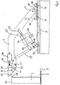
- 1 is a container which is placed on the bottom 2 of the compartment of a circulation rack, not shown.
- a stop ramp 3 is arranged, which prevents the container 1 from sliding out under centrifugal force when passing the deflection points of the deflection shelf.
- a shelf 4 is placed in front of the shelf 2, onto which the container 1 can be transferred using a device described in more detail below.
- This device has two gripper arms 5 and 6 which are arranged at a distance from one another and are connected to one another via a pivot axis 7 which is pivotably mounted in bearing blocks 8 and 9.
- the bearing blocks 8 and 9 form parts of a carriage or carriage 10, the rollers 11 of which are guided by guide rails 12 and 13.
- Adjustable stops 14, 15 hold the gripper arms 5 and 6 in their starting position.
- the cross member 16 has boom 19 with rollers 20 which are supported on the table 4.
- a link consisting of two parts 22 and 23 engages on a projection 21 of the cross member 16.
- Part 22 of the handlebar includes a piston 24 and part 23 a cylinder 25.
- the piston 24 and the cylinder 25 form a hydraulic unit, for the control of which a 2/2-way valve 26 is used (FIG. 2).
- the 2/2-way valve 26 prevents the exchange of a fluid between the two chambers of the cylinder 25 separated by the piston 24, while in an open position it permits such an exchange.
- the support and lifting arms 17, 18 assume an unchangeable position in the locked position.
- the gripper arms 5, 6, are each provided with a recess 27 into which a part of the container 1, and preferably a flange 28 at the upper edge 29 of the container 1, can be immersed.
- the free ends of the gripper arms 5, 6 form sliding runners 30 which slide on the ramp 28 as they approach the container 1.
- gripper hands 32, 33 mounted counterclockwise against the action of a spring, not shown, so that it can penetrate into the recess 27 .
- the gripper hands 32, 33 have the shape of a hook, the prong 34 of which is connected to a cross bar 36 by means of a shaft 35.
- One end of the crossbar 36 surrounds the pivot axis 31, while the actuating rod 37 of a control mechanism 38 engages at the other end, through which the gripper hands 32, 33 can be removed from their gripping position.
- the prongs 34 of the gripper hands 32, 33 come into the gripping position under the action of the spring already mentioned as soon as the upper edge 29 of the container 1 has been run over by them.
- a lifting magnet is expediently used as the control mechanism 38, in the housing of which the spring urging the prong 34 into its gripping position is installed.
- the prong 34 of the gripper hands 32, 33 is arranged in a plane running above the pivot axis 31, it automatically holds itself in the gripping position by the force acting on it causing a closing moment, the magnitude of which is proportional to the magnitude of the force.
- the 2/2-way valve 26 When the carriage or carriage 10 is moved into the gripping position, the 2/2-way valve 26 is open, i.e. the support and lifting arms 17, 18 can perform pivoting movements. If the container 1 is to be transferred from the shelf 2 to the table 4, the 2/2-way valve 26 is closed. The result is that the support and lifting arms 17, 18 are locked in their position. If the carriage or carriage 10 then moves back, the gripper hands 32, 33 pull it from the shelf. The rollers 20 of the support and lifting arms 17, 18 reach the area of control cams 39, 40, and there is a pivoting movement of the gripper arms 5, 6 about the pivot axis 7. The gripper arms 5, 6 consequently lift the front part of the container 1 over the stop ramp 3 of the shelf 2, and the container 1 is transferred smoothly from the shelf to the table 4.
- the 2/2-way valve 26 can be opened again and the gripper hands 32, 33 can be moved back into a release position by the control mechanism 38.
- the back and forth movement in the carriage or carriage 10 is initiated via a spindle drive, the spindle 41 of which is indicated in FIG. 1.
- FIGS. 3 and 4 show two modifications of the devices shown in FIGS. 1 and 2, the same reference numerals being used for parts which correspond to parts in FIGS. 1 and 2 and only the differences between the constructions below be discussed.
- control cams for lifting the gripper arms 5, 6 are dispensed with, and instead the hydraulic unit consisting of the piston 24 and the cylinder 25 is used to initiate lifting movements in the gripper arms 5, 6, in this case a 4th / 3-way valve 42 is assigned.
- the 4/3-way valve 42 is connected to a pump that can deliver oil from a reservoir 44.
- the 4/3-way valve is moved into position I. This means that the roller 20 can touch the table. Then the 4/3-way valve is switched to position III and the pump 43 is started up.
- Oil thus gets into the right chamber of the cylinder 25, and the piston 24 is shifted to the left. He pivots the rocker formed by the support and lifting arms 17, 18 in a clockwise direction, and the part of the container 1 gripped by the gripper arms 5 and 6 is raised. As soon as the desired height is reached, the 4/3-way valve is switched to position II and the pump 43 is stopped. In position II, the position of the gripper arms 5, 6 is locked, and the carriage or slide 10 can move back to its starting position, taking the container 1 with it.
- a spindle lifting gear 45 is used to lift the gripper arms 5, 6.
- the spindle 46 of the spindle lifting gear 45 becomes so far extended until the roller 20 touches the table 4. If the spindle 46 is then extended by a further amount, the part of the container 1 gripped by the gripper hand is also raised in this case, and this can in turn be pulled from the bottom 2 of the compartment without the stop ramp 3 adversely affecting the outsourcing process influenced.
Landscapes
- Engineering & Computer Science (AREA)
- Mechanical Engineering (AREA)
- Warehouses Or Storage Devices (AREA)
Abstract
Description
Die Erfindung betrifft eine Vorrichtung zum Ein- und Auslagern eines Behälters oder anderen Gegenstandes in das bzw. aus dem Fach eines Regales, insbesondere Umlaufregales, mit Hilfe eines hin- und herbewegbaren Laufwagens oder Schlittens für mindestens einen Greiferarm, der an seinem freien Ende eine Greiferhand zum Erfassen eines Teiles des Behälters aufweist.The invention relates to a device for storing and retrieving a container or other object in or out of the compartment of a shelf, in particular a circulating shelf, with the aid of a reciprocating carriage or slide for at least one gripper arm which has a gripper hand at its free end for grasping a part of the container.
Aus der DE-36 10 347 Al ist eine Vorrichtung der vorstehenden Art bekannt, bei der zwei Greiferarme beidseits eines ein- bzw. auszulagernden Behälters in Schlitze eines Umlaufregalfaches fahren können. Dem Greiferarm sind hier leistenförmige Transporthilfen an den Längsseiten des Behälters zugeordnet, über die sich der Behälter auf den Greiferarm abstützen kann, wenn das Fach des Umlaufregales um einen bestimmten Betrag abgesenkt wird. Die beschriebene Anordnung ermöglicht es, den jeweiligen Behälter ungehindert über die bei Umlaufregalen praktisch unverzichtbaren Anschlagrampen am vorderen Rand des Regalfaches zu befördern, dies allerdings mit einem erheblichen sowohl konstruktiven als auch steuertechnischen Aufwand.From DE-36 10 347 A1 a device of the above type is known, in which two gripper arms can travel on both sides of a container to be stored or removed into slots in a circulation rack compartment. The gripper arm here is assigned strip-shaped transport aids on the long sides of the container, via which the container can be supported on the gripper arm when the compartment of the circulation rack is lowered by a certain amount. The arrangement described makes it possible to transport the respective container unhindered via the stop ramps at the front edge of the rack compartment which are practically indispensable in the case of circulating racks, but this requires considerable expenditure in terms of both design and control technology.
Der Erfindung liegt die Aufgabe zugrunde, eine Vorrichtung der in Betracht gezogenen Art zu schaffen, mit der es bei einfachem Aufbau und ohne die Notwendigkeit einer Verlagerung von Regalfächern möglich ist, insbesondere in Umlaufregalen gelagerte Behälter oder andere Gegenstände ruckfrei über am vorderen Rand von Regalfächern angeordnete Anschlagrampen zu transportieren.The invention has for its object to provide a device of the type under consideration, with which it is possible with a simple structure and without the need to relocate shelves, in particular containers or other objects stored in circulating shelves without jerking over the front edge of shelves Transport stop ramps.
Die vorstehende Aufgabe wird erfindungsgemäß dadurch gelöst, daß der Greiferarm als Huborgan für den von der Greiferhand erfaßten Teil des Behälters ausgebildet ist.The above object is achieved in that the gripper arm is designed as a lifting element for the part of the container gripped by the gripper hand.
Die erfindungsgemäße Vorrichtung bietet den Vorteil, daß mit ihr ohne großen Steuerungsaufwand Behälter ruckfrei aus Regalfächern mit Anschlagrampen ausgelagert werden können, indem das von der Greiferhand erfaßte vordere Ende des jeweiligen Behälters durch den Greiferarm über die Anschlagrampe gehoben wird.The device according to the invention has the advantage that it can be used to swiftly move containers out of shelves with stop ramps without great control effort, by lifting the front end of the respective container gripped by the gripper hand through the gripper arm over the stop ramp.
In weiterer Ausgestaltung der Erfindung wird die Greiferhand unter Verzicht auf Sensoren automatisch dadurch in die richtige Greifposition geführt, daß das Ende des Greiferarmes eine Gleitkufe bildet, die beim Aufgleiten auf einen Teil des Behälters die Greiferhand in die Greifstellung überführt. Toleranzen hinsichtlich der Positionierung des Behälters werden auf diese Art und Weise zwangsläufig ausgeglichen.In a further embodiment of the invention, the gripper hand is automatically guided into the correct gripping position by dispensing with sensors in that the end of the gripper arm forms a skid which, when sliding onto a part of the container, transfers the gripper hand into the gripping position. Tolerances regarding the positioning of the container are inevitably compensated for in this way.
Weitere Einzelheiten und Merkmale der Erfindung ergeben sich aus den Unteransprüchen und der nachstehenden Beschreibung mehrerer in der beigefügten Zeichnung dargestellter Ausführungsbeispiele. Es zeigen mehr oder weniger schematisch:
- Fig. 1 eine perspektivische Ansicht einer bevorzugten Ausführungsform,
- Fig. 2 die Seitenansicht eines Greiferarmes der Vorrichtung gemäß Figur 1,
- Fig. 3 die Seitenansicht einer ersten modifizierten Ausführungsform und
- Fig. 4 die Seitenansicht einer zweiten modifizierten Ausführungsform.
- 1 is a perspective view of a preferred embodiment,
- 2 shows the side view of a gripper arm of the device according to FIG. 1,
- Fig. 3 is a side view of a first modified embodiment and
- Fig. 4 is a side view of a second modified embodiment.
In Figur 1 ist 1 ein Behälter, der auf dem Boden 2 des Faches eines nicht gezeigten Umlaufregales abgestellt ist. Am vorderen Rand des Fachbodens 2 ist eine Anschlagrampe 3 angeordnet, die verhindert, daß der Behälter 1 beim Passieren der Umlenkstellen des Umlenkregales unter Fliehkrafteinwirkung nach außen rutscht.In Figure 1, 1 is a container which is placed on the
An der Be- und Entladestelle des Umlaufregales ist dem Fachboden 2 ein Tisch 4 vorgelagert, auf den der Behälter 1 mit Hilfe einer im folgenden näher beschriebenen Vorrichtung überführt werden kann. Diese Vorrichtung weist zwei im Abstand voneinander angeordnete Greiferarme 5 und 6 auf, die über eine Schwenkachse 7 miteinander in Verbindung stehen, welche schwenkbar in Lagerböcken 8 und 9 gelagert ist. Die Lagerböcke 8 und 9 bilden Teile eines Laufwagens oder Schlittens 10, dessen Laufrollen 11 durch Führungsschienen 12 und 13 geführt sind. Einstellbare Anschläge 14,15 halten die Greiferarme 5 und 6 in ihrer Ausgangsposition.At the loading and unloading point of the circulating rack, a
Im Abstand von der Schwenkachse 7 der Greiferarme 5,6 sind an diesen schwenkbar über einen Querträger 16 miteinander verbundene Stütz- und Hubarme 17,18 gelagert. Der Querträger 16 weist Ausleger 19 mit Rollen 20 auf, die sich auf dem Tisch 4 abstützen. An einem Vorsprung 21 des Querträgers 16 greift ein aus zwei Teilen 22 und 23 bestehender Lenker an. Zum Teil 22 des Lenkers gehört ein kolben 24 und zum Teil 23 ein Zylinder 25. Der kolben 24 und der Zylinder 25 bilden ein Hydraulikaggregat, zu dessen Steuerung ein 2/2-Wegeventil 26 dient (Fig. 2).At a distance from the pivot axis 7 of the
Das 2/2-Wegeventil 26 verhindert in einer Sperrstellung den Austausch eines Fluids zwischen den beiden durch den Kolben 24 getrennten Kammern des Zylinders 25, während es in einer Offenstellung einen derartigen Austausch zuläßt. Infolge der Inkompressibilität des Fluids nehmen die Stütz-und Hubarme 17,18 in der Sperrstellung eine unveränderbare Position ein.In a blocking position, the 2/2-
Am freien Ende der Greiferarme 5,6 sind diese mit jeweils einer Ausnehmung 27 versehen, in die ein Teil des Behälters 1, und zwar vorzugsweise ein Flansch 28 am oberen Rand 29 des Behälters 1, eintauchen kann. Um den Flansch automatisch in die Ausnehmung 27 überführen zu können, formen die freien Enden der Greiferarme 5,6 Gleitkufen 30, die im Zuge ihrer Annäherung an den Behälter 1 auf dessen Rampe 28 gleiten. Sobald der Flansch 28 in den Bereich der Ausnehmung 27 gelangt ist, schwenkt er drehbar auf einer Schwenkachse 31 an den Greiferarmen 5,6 gelagerte Greiferhände 32,33 gegen die Wirkung einer nicht dargestellten Feder im Uhrzeigersinn, so daß er in die Ausnehmung 27 eindringen kann. Die Greiferhände 32,33 haben die Form eines Hakens, dessen Zinke 34 über einen Schaft 35 mit einem Querbalken 36 verbunden ist. Das eine Ende des Querbalkens 36 umschließt die Schwenkachse 31, während an das andere Ende die Betätigungsstange 37 eines Steuermechanismus 38 angreift, durch den die Greiferhände 32,33 aus ihrer Greifstellung entfernbar sind. In die Greifstellung gelangen die Zinken 34 der Greiferhände 32,33 unter der Einwirkung der bereits erwähnten Feder, sobald der obere Rand 29 des Behälters 1 von ihnen überfahren worden ist. Als Steuermechanismus 38 wird zweckmäßigerweise ein Hubmagnet verwendet, in dessen Gehäuse die die Zinke 34 in ihre Greifposition drängende Feder eingebaut ist. Dadurch, daß man die Zinke 34 der Greiferhände 32,33 in einer oberhalb der Schwenkachse 31 verlaufenden Ebene anordnet, hält sie sich selbsttätig in der Greifposition, indem die an sie angreifende Kraft ein schließendes Moment bewirkt, dessen Größe der Größe der Kraft proportional ist.At the free end of the
Beim Einfahren des Laufwagens bzw. Schlittens 10 in die Greifposition ist das 2/2-Wegeventil 26 geöffnet, d.h. die Stütz- und Hubarme 17,18 können Schwenkbewegungen ausführen. Soll der Behälter 1 vom Fachboden 2 auf den Tisch 4 überführt werden, so wird das 2/2-Wegeventil 26 geschlossen. Die Folge ist, daß die Stütz- und Hubarme 17,18 in ihrer Position arretiert werden. Fährt der Laufwagen bzw. Schlitten 10 anschließend zurück, so ziehen die Greiferhände 32,33 ihn vom Fachboden. Dabei gelangen die Rollen 20 der Stütz- und Hubarme 17,18 in den Bereich von Steuerkurven 39,40, und es kommt zu einer Schwenkbewegung der Greiferarme 5,6 um die Schwenkachse 7. Die Greiferarme 5,6 heben folglich den vorderen Teil des Behälters 1 über die Anschlagrampe 3 des Fachbodens 2, und der Behälter 1 wird ruckfrei vom Fachboden auf den Tisch 4 überführt. Sobald der Behälter 1 ganz auf den Tisch 4 gelangt ist, können das 2/2-Wegeventil 26 wieder geöffnet und durch den Steuermechanismus 38 die Greiferhände 32,33 in eine Freigabestellung zurückbewegt werden. Die Einleitung der Hin- und Herbewegung in den Laufwagen bzw. Schlitten 10 erfolgt über einen Spindeltrieb, dessen Spindel 41 in Figur 1 angedeutet ist.When the carriage or
In den Figuren 3 und 4 sind zwei Modifikationen der in den Figuren 1 und 2 dargestellten Vorrichtungen gezeigt, wobei für Teile, die Teilen in den Figuren 1 und 2 entsprechen, gleiche Bezugszeichen verwendet und im folgenden lediglich noch die Unterschiede zwischen den Konstruktionen erörtert werden.FIGS. 3 and 4 show two modifications of the devices shown in FIGS. 1 and 2, the same reference numerals being used for parts which correspond to parts in FIGS. 1 and 2 and only the differences between the constructions below be discussed.
Bei der Vorrichtung gemäß Fig. 3 wird auf Steuerkurven zum Anheben der Greiferarme 5,6 verzichtet und statt dessen zur Einleitung von Hubbewegungen in die Greiferarme 5,6 das aus dem kolben 24 und dem Zylinder 25 bestehende Hydraulikaggregat genutzt, dem in diesem Fall ein 4/3-Wegeventil 42 zugeordnet ist. Das 4/3-Wegeventil 42 steht mit einer Pumpe in Verbindung, die Öl aus einem Reservoir 44 fördern kann. Sobald der Flansch 28 des Behälters 1 in die Ausnehmung 27 eingefahren ist und die Greiferhand 32 den oberen Rand 29 des Behälters 1 erfaßt hat, wird das 4/3-Wegeventil in die Stellung I überführt. Dies bedeutet, daß die Rolle 20 auf den Tisch aufsetzen kann. Anschließend wird das 4/3-Wegeventil in die Stellung III umgeschaltet und die Pumpe 43 in Betrieb genommen. Es gelangt mithin Öl in die rechte kammer des Zylinders 25, und der kolben 24 wird nach links verschoben. Dabei schwenkt er die von den Stütz- und Hubarmen 17,18 gebildete Schwinge im Uhrzeigersinn, und der von den Greiferarmen 5 und 6 erfaßte Teil des Behälters 1 wird angehoben. Sobald die erwünschte Höhe erreicht ist, wird das 4/3-Wegeventil in die Stellung II geschaltet und die Pumpe 43 stillgesetzt. In der Stellung II ist die Position der Greiferarme 5,6 arretiert, und der Laufwagen bzw. Schlitten 10 kann sich unter Mitnahme des Behälters 1 zurück in seine Ausgangslage bewegen.In the device according to FIG. 3, control cams for lifting the
Bei der Ausführungsform gemäß Figur 4 schließlich dient zum Anheben der Greiferarme 5,6 ein Spindelhubgetriebe 45. Hat die Greiferhand 32 den Behälter 1 erfaßt, so wird die Spindel 46 des Spindelhubgetriebes 45 so weit ausgefahren, bis die Rolle 20 auf den Tisch 4 aufsetzt. Fährt man anschließend die Spindel 46 um einen weiteren Betrag aus, so erfolgt auch in diesem Fall ein Anheben des von der Greiferhand erfaßten Teiles des Behälters 1, und dieser kann wiederum vom Boden 2 des Faches gezogen werden, ohne daß die Anschlagrampe 3 den Auslagervorgang nachteilig beeinflußt.Finally, in the embodiment according to FIG. 4, a
Claims (22)
Applications Claiming Priority (4)
| Application Number | Priority Date | Filing Date | Title |
|---|---|---|---|
| DE19914100359 DE4100359C2 (en) | 1991-01-04 | 1991-01-04 | Device for storing and retrieving a container from or on a shelf |
| DE4100360 | 1991-01-04 | ||
| DE19914100360 DE4100360C2 (en) | 1991-01-04 | 1991-01-04 | Device for storing and retrieving a container from or on a shelf |
| DE4100359 | 1991-01-04 |
Publications (1)
| Publication Number | Publication Date |
|---|---|
| EP0494101A1 true EP0494101A1 (en) | 1992-07-08 |
Family
ID=25900129
Family Applications (1)
| Application Number | Title | Priority Date | Filing Date |
|---|---|---|---|
| EP92250001A Withdrawn EP0494101A1 (en) | 1991-01-04 | 1992-01-03 | Device for moving and removing a container from or onto a shelf |
Country Status (1)
| Country | Link |
|---|---|
| EP (1) | EP0494101A1 (en) |
Cited By (1)
| Publication number | Priority date | Publication date | Assignee | Title |
|---|---|---|---|---|
| CN110159322A (en) * | 2019-06-05 | 2019-08-23 | 四川蓝海智能装备制造有限公司 | A kind of clamping device and steel arch-shelf installation trolley for steel arch-shelf |
Citations (3)
| Publication number | Priority date | Publication date | Assignee | Title |
|---|---|---|---|---|
| GB2101574A (en) * | 1981-07-09 | 1983-01-19 | Sps Technologies | Retrieval and storage mechanism for use with an automated rotary storage unit |
| DE3610347A1 (en) * | 1986-03-27 | 1987-10-01 | Fraunhofer Ges Forschung | Storage apparatus |
| DE3837152A1 (en) * | 1988-11-02 | 1990-05-03 | Reinders Kunststoff Gmbh | Transporting and unloading device for poultry transport boxes, and poultry transport box therefor |
-
1992
- 1992-01-03 EP EP92250001A patent/EP0494101A1/en not_active Withdrawn
Patent Citations (3)
| Publication number | Priority date | Publication date | Assignee | Title |
|---|---|---|---|---|
| GB2101574A (en) * | 1981-07-09 | 1983-01-19 | Sps Technologies | Retrieval and storage mechanism for use with an automated rotary storage unit |
| DE3610347A1 (en) * | 1986-03-27 | 1987-10-01 | Fraunhofer Ges Forschung | Storage apparatus |
| DE3837152A1 (en) * | 1988-11-02 | 1990-05-03 | Reinders Kunststoff Gmbh | Transporting and unloading device for poultry transport boxes, and poultry transport box therefor |
Non-Patent Citations (1)
| Title |
|---|
| PATENT ABSTRACTS OF JAPAN vol. 7, no. 110 (M-214)(1255) 13. Mai 1983 & JP-A-58 031 801 ( HITACHI SEISAKUSHO ) 24. Februar 1983 * |
Cited By (1)
| Publication number | Priority date | Publication date | Assignee | Title |
|---|---|---|---|---|
| CN110159322A (en) * | 2019-06-05 | 2019-08-23 | 四川蓝海智能装备制造有限公司 | A kind of clamping device and steel arch-shelf installation trolley for steel arch-shelf |
Similar Documents
| Publication | Publication Date | Title |
|---|---|---|
| DE19712641A1 (en) | Transfer device for pipe shots | |
| CH655268A5 (en) | TOOL CHANGER FOR MOLDING MACHINE. | |
| DE2725134A1 (en) | GRIPPING DEVICE FOR TOP OPEN CONTAINERS | |
| DE19525018C2 (en) | Device for gripping and weight-dependent clamping of workpieces, rail guides or the like which are to be moved or held relative to a local position. | |
| DE60308400T2 (en) | ROLLER TRACK DEVICE FOR MOVING A LOAD IN AN ESSENTIALLY HORIZONTAL LEVEL | |
| EP2218666B1 (en) | Pivoting stop for items grouped on a support surface | |
| DE3633508C2 (en) | ||
| EP0116126A1 (en) | Shelf with at least one storage and retrieval machine | |
| DE3247158A1 (en) | Shelving arrangement with at least one storage and retrieval unit | |
| DE3741257A1 (en) | Gripping apparatus, in particular for lying nested stacks of plastic beakers | |
| EP0494101A1 (en) | Device for moving and removing a container from or onto a shelf | |
| DE4100359C2 (en) | Device for storing and retrieving a container from or on a shelf | |
| AT524051B1 (en) | Device for shifting transport containers between a stack of containers and a container rack | |
| DE4100360C2 (en) | Device for storing and retrieving a container from or on a shelf | |
| CH534624A (en) | Process and device for the removal of stored goods from shelves open on one side | |
| DE3907332A1 (en) | Gripping device | |
| EP1244596B1 (en) | Add-on for industrial trucks, especially lift trucks | |
| DE2538710C3 (en) | Transfer device for bottles or the like. container | |
| DE3507283C2 (en) | ||
| EP0319880A1 (en) | Feeding device for pallets | |
| DE1258792B (en) | Method and device for laterally moving apart and separating out elongated square objects | |
| DE1152352B (en) | Device for automatic packing of bottles in boxes | |
| DE2731579A1 (en) | Steel angle stacking machine - has magnets on rocker arms pivoting on lifting mechanism working with control lever | |
| DE1782670A1 (en) | METHOD AND MACHINE FOR DELIVERY OF MOLS FROM A STACK OF MOLDS TO A DOWNSTREAM MACHINE | |
| DE4233709C2 (en) | Device for handling loads |
Legal Events
| Date | Code | Title | Description |
|---|---|---|---|
| PUAI | Public reference made under article 153(3) epc to a published international application that has entered the european phase |
Free format text: ORIGINAL CODE: 0009012 |
|
| AK | Designated contracting states |
Kind code of ref document: A1 Designated state(s): AT BE CH DE DK ES FR GB GR IT LI LU NL PT SE |
|
| 17P | Request for examination filed |
Effective date: 19930107 |
|
| 17Q | First examination report despatched |
Effective date: 19940408 |
|
| STAA | Information on the status of an ep patent application or granted ep patent |
Free format text: STATUS: THE APPLICATION HAS BEEN WITHDRAWN |
|
| 18W | Application withdrawn |
Withdrawal date: 19940818 |