EP0493907A1 - Cutting press having movable cutting head - Google Patents
Cutting press having movable cutting head Download PDFInfo
- Publication number
- EP0493907A1 EP0493907A1 EP91311498A EP91311498A EP0493907A1 EP 0493907 A1 EP0493907 A1 EP 0493907A1 EP 91311498 A EP91311498 A EP 91311498A EP 91311498 A EP91311498 A EP 91311498A EP 0493907 A1 EP0493907 A1 EP 0493907A1
- Authority
- EP
- European Patent Office
- Prior art keywords
- cutting
- cutting head
- press
- movement
- drive means
- Prior art date
- Legal status (The legal status is an assumption and is not a legal conclusion. Google has not performed a legal analysis and makes no representation as to the accuracy of the status listed.)
- Withdrawn
Links
- 239000004020 conductor Substances 0.000 claims abstract description 3
- 230000000694 effects Effects 0.000 claims description 6
- 239000000463 material Substances 0.000 abstract description 3
- 239000012530 fluid Substances 0.000 description 4
- 239000007787 solid Substances 0.000 description 4
- 230000006835 compression Effects 0.000 description 3
- 238000007906 compression Methods 0.000 description 3
- 230000001276 controlling effect Effects 0.000 description 2
- 230000000266 injurious effect Effects 0.000 description 2
- 230000035515 penetration Effects 0.000 description 2
- 239000006261 foam material Substances 0.000 description 1
- 230000004886 head movement Effects 0.000 description 1
- 230000002452 interceptive effect Effects 0.000 description 1
- 230000013011 mating Effects 0.000 description 1
- 230000001105 regulatory effect Effects 0.000 description 1
- 239000012858 resilient material Substances 0.000 description 1
Images
Classifications
-
- B—PERFORMING OPERATIONS; TRANSPORTING
- B26—HAND CUTTING TOOLS; CUTTING; SEVERING
- B26D—CUTTING; DETAILS COMMON TO MACHINES FOR PERFORATING, PUNCHING, CUTTING-OUT, STAMPING-OUT OR SEVERING
- B26D7/00—Details of apparatus for cutting, cutting-out, stamping-out, punching, perforating, or severing by means other than cutting
- B26D7/22—Safety devices specially adapted for cutting machines
- B26D7/24—Safety devices specially adapted for cutting machines arranged to disable the operating means for the cutting member
-
- B—PERFORMING OPERATIONS; TRANSPORTING
- B23—MACHINE TOOLS; METAL-WORKING NOT OTHERWISE PROVIDED FOR
- B23Q—DETAILS, COMPONENTS, OR ACCESSORIES FOR MACHINE TOOLS, e.g. ARRANGEMENTS FOR COPYING OR CONTROLLING; MACHINE TOOLS IN GENERAL CHARACTERISED BY THE CONSTRUCTION OF PARTICULAR DETAILS OR COMPONENTS; COMBINATIONS OR ASSOCIATIONS OF METAL-WORKING MACHINES, NOT DIRECTED TO A PARTICULAR RESULT
- B23Q11/00—Accessories fitted to machine tools for keeping tools or parts of the machine in good working condition or for cooling work; Safety devices specially combined with or arranged in, or specially adapted for use in connection with, machine tools
- B23Q11/04—Arrangements preventing overload of tools, e.g. restricting load
-
- C—CHEMISTRY; METALLURGY
- C14—SKINS; HIDES; PELTS; LEATHER
- C14B—MECHANICAL TREATMENT OR PROCESSING OF SKINS, HIDES OR LEATHER IN GENERAL; PELT-SHEARING MACHINES; INTESTINE-SPLITTING MACHINES
- C14B5/00—Clicking, perforating, or cutting leather
-
- F—MECHANICAL ENGINEERING; LIGHTING; HEATING; WEAPONS; BLASTING
- F16—ENGINEERING ELEMENTS AND UNITS; GENERAL MEASURES FOR PRODUCING AND MAINTAINING EFFECTIVE FUNCTIONING OF MACHINES OR INSTALLATIONS; THERMAL INSULATION IN GENERAL
- F16P—SAFETY DEVICES IN GENERAL; SAFETY DEVICES FOR PRESSES
- F16P3/00—Safety devices acting in conjunction with the control or operation of a machine; Control arrangements requiring the simultaneous use of two or more parts of the body
- F16P3/12—Safety devices acting in conjunction with the control or operation of a machine; Control arrangements requiring the simultaneous use of two or more parts of the body with means, e.g. feelers, which in case of the presence of a body part of a person in or near the danger zone influence the control or operation of the machine
- F16P3/16—Safety devices acting in conjunction with the control or operation of a machine; Control arrangements requiring the simultaneous use of two or more parts of the body with means, e.g. feelers, which in case of the presence of a body part of a person in or near the danger zone influence the control or operation of the machine with feeling members moved by the machine
-
- F—MECHANICAL ENGINEERING; LIGHTING; HEATING; WEAPONS; BLASTING
- F16—ENGINEERING ELEMENTS AND UNITS; GENERAL MEASURES FOR PRODUCING AND MAINTAINING EFFECTIVE FUNCTIONING OF MACHINES OR INSTALLATIONS; THERMAL INSULATION IN GENERAL
- F16P—SAFETY DEVICES IN GENERAL; SAFETY DEVICES FOR PRESSES
- F16P3/00—Safety devices acting in conjunction with the control or operation of a machine; Control arrangements requiring the simultaneous use of two or more parts of the body
- F16P3/18—Control arrangements requiring the use of both hands
- F16P3/20—Control arrangements requiring the use of both hands for electric control systems
Definitions
- This invention is concerned with a cutting press comprising a cutting bed, a cutting head movable between an operative position, in which it is in opposed relationship with a cutting die placed on the cutting bed, and an out-of-the-way position, in which the operator has access to such cutting die, and drive means for effecting relative movement of approach between the cutting head and the cutting bed whereby, when the cutting head is in its operative position, a cutting stroke of the press can be effected.
- the invention is thus applicable to so-called “travelling head” cutting presses and also “receding platen” cutting presses, but is particularly, but not exclusively, concerned with so-called “swing beam” cutting presses wherein the cutting head is constituted by a swing beam mounted on a column for swinging movement between its operative and out-of-the-way positions.
- Cutting presses of all kinds require some form of guarding in order to prevent access by a party other than the operator from the area in which the cutting head is moved and at which it effects its cutting stroke, and in addition some form of actuator arrangement is generally provided whereby the hands of the operator must be outside such region when a cutting stroke is to be effected, e.g. a so-called two-hand trip arrangement. In this way the risk of damage to the operator or any third party can be avoided.
- the main risk of damage is of course that of trapping a hand against a cutting die during the cutting stroke, which could have serious consequences, but in addition in the case of cutting presses having movable cutting heads, as referred to above, there is also a danger to third parties by the cutting head movement, if such third parties are allowed access to the region of such movement, and in addition of course it is possible for the operator to trap his hand between the cutting head and a cutting die placed on the cutting bed during such movement.
- the risk of trapping in this way arises not only where the movement of the cutting head is effected under power, furthermore, but also when it is effected manually.
- One cutting press in accordance with the invention comprising a cutting bed, a cutting head movable between an operative position, in which it is in opposed relationship with a cutting die placed on the cutting bed, and an out-of-the-way position, in which the operator has access to such cutting die, and drive means for effecting relative movement of approach between the cutting head and the cutting bed, thus to effect a cutting stroke of the press, wherein sensor means is provided comprising, on each side of the cutting head, a pad arrangement comprising two pads of resilient and electrically conductive material held separated by spaced-apart rib portions, each such pad arrangement being effective, when compressed, e.g. by engagement thereof with an obstruction in the path of movement of the cutting head, to make an electrical circuit and thus to generate a signal in response to which the drive means is disabled to prevent a cutting stroke of the press from being effected.
- each pad arrangement preferably does not exceed 30mm, and moreover in the region of the striker plate of the cutting head (i.e. around the lower edge thereof) the edge of each pad is chamfered, rounded or the like. It has been found that in this way the view of the operator over the operating area of the cutting bed is relatively unimpeded by the pad arrangement.
- brake means is provided by which, in response to said signal, movement of the cutting head is arrested.
- the brake means is effective so as to arrest the movement of the cutting head within a distance which is not greater than the variation in the thickness of the pad arrangement when it is compressed. In this way effectively the pad cushions the whole of the impact of the moving cutting head against an obstruction and, by the time the pad arrangement is fully compressed, the movement of the cutting head has been terminated.
- the present invention is applicable to cutting presses where the cutting head is moved by manually applied force, in a preferred embodiment of the invention, however, further drive means is provided for effecting movement of the cutting head between its operative and out-of-the-way positions.
- further drive means is provided for effecting movement of the cutting head between its operative and out-of-the-way positions.
- Such a cutting press furthermore, preferably in response to a signal being generated as aforesaid when the cutting head is being moved under the operation of the further drive means, such operation of said further drive means is discontinued.
- the further drive means preferably applies a force to the cutting head to move it as aforesaid which force is such that in response to a signal being generated as aforesaid movement of the cutting head under the operation of the further drive means is arrested within a distance not greater than the variation in the thickness of the pad arrangement when it is compressed.
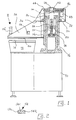
- the cutting press shown in Figure 1 is a swing beam cutting press comprising a base 10 which supports a cutting table or bed 12, a cutting surface of which is provided by a cutting pad 14 supported on the bed.
- a base 10 which supports a cutting table or bed 12, a cutting surface of which is provided by a cutting pad 14 supported on the bed.
- an upstanding column 16 Secured on the base 10, rearwardly of the cutting bed 12, is an upstanding column 16 which is hollow and the upper end of which constitutes a cylinder 18 forming part of a hydraulic piston-and-cylinder arrangement the piston 20 of which is mounted for heightwise sliding movement in the cylinder when hydraulic fluid is applied thereto.
- the piston is secured against rotation in the cylinder by means of a splined shaft 22 fixedly secured to the base of the cylinder and projecting through, and mating with, a complementarily shaped bore in the piston.
- the piston carries an upwardly extending piston rod 24 which projects through an end cap 26 of the cylinder 18 and has at its upper end a portion of reduced diameter 28, thus providing an annular support surface 30 on which a housing 32 is carried.
- the housing 32 is bolted to a plate 34 which is turn is welded to a sleeve 36 slidable heightwise on the outside of the column 16.
- the plate 34 also constitutes the top plate of a swing beam 38 which is also welded or otherwise secured to the sleeve 36.
- the swing beam 38 carries a striker plate 40 on its underside.
- the reduced diameter portion 28 of the piston rod 24 is threaded and threadedly receives a nut 42 which is formed integral with a gear 44. Meshing with the gear 44 is further gear 46 carried on a drive shaft of a d.c. motor 48 mounted on the outside of the housing 32.
- the plate 34 carries a cover 50 which shrouds the gears 44, 46, the housing 32 and motor 48.
- the gear 46 Upon the supply of drive signals to the d.c. motor 48 causing rotation of the gear 46 to take place, the gear 46 thus runs around the circumference of the gear 44 fixed on the piston rod 24, thereby moving the housing 32 and thus the swing beam 38 about the axis provided by the piston rod.
- a switch arrangement generally designated 52 (Figure 2), comprising three switches 54, is provided mounted in a handle 56 on the swing beam 38, together with an actuator arrangement comprising two buttons 58 arranged one at each side of the swing beam 38.
- the depth of penetration of a cutting die i.e. the depth to which a cutting die is driven through material, which is supported on the cutting pad 14 and over which the cutting die is then placed, into the cutting pad 14 can be selectively varied according to which one of the three switches 54 is selected for actuation.
- the distance through which the beam is moved downwardly may be varied according to the particular switch selected.
- the time during which the cutting pressure is maintained or the applied pressure may be varied according to the switch selected.
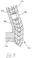
- a sensor pad arrangement 60 see Figure 3
- the pads 62,64 are electrically conductive and the ribs insulating, the arrangement being such that compression brings the pads into contact and in response thereto a signal can be supplied.
- a pad arrangement of this type is available from MAYSER GMBH & Co, of Ulm, Germany, and is identified as an Electronic Safety System.
- the pad arrangements 60 covers the whole of each side of the swing beam, each with a cut-out for its associated button 58, and also wraps around the lower edge of the beam.
- Each pad arrangement is 30mms thick, allowing some 20mms of movement of the swing beam after initial contact with an obstruction before it becomes "solid" with the swing beam.
- the press thus further comprises brake means which is actuated in response to contact being made between the pads 62, 64.
- this brake means is incorporated with the motor 48.
- the compression of the pad arrangement 60 generates a signal which not only actuates the brake means as aforesaid, but also serves to discontinue the current supply to the motor 48 driving the swing beam in the selected direction and indeed to reverse the current supply so as to initiate the driving of the beam for a short time period in the opposite direction.
- separate brake means must of course be provided, which also act in the same manner as described above.
- the motor 48 is of a type in which the force applied thereby is proportional to the current supplied to it; in the particular case, this motor 48 is a d.c. electric motor.
- this motor 48 is a d.c. electric motor.
- it is merely necessary to control the supply of current, it being of course appreciated that in the normal operation of a d.c. motor, the current will rise as the load, and thus the turning moment to overcome such load, rises.
- the current supply to the motor 48 is constantly monitored and limited to a pre-set value such that the force which the beam applies to any obstruction, e.g. the hand of the operator or third party does not exceed 50 Newtons by the time the pad arrangement 60 has been compressed and the pads 62, 64 have become solid with the swing beam. It is of course to be appreciated that this force will vary along the length of the beam from its pivot, and the limit of 50 Newtons applies through the whole of the length of the beam.
Landscapes
- Engineering & Computer Science (AREA)
- Mechanical Engineering (AREA)
- General Engineering & Computer Science (AREA)
- Chemical & Material Sciences (AREA)
- Organic Chemistry (AREA)
- Life Sciences & Earth Sciences (AREA)
- Forests & Forestry (AREA)
- Presses And Accessory Devices Thereof (AREA)
- Shearing Machines (AREA)
- Perforating, Stamping-Out Or Severing By Means Other Than Cutting (AREA)
- Nonmetal Cutting Devices (AREA)
- Control Of Presses (AREA)
Applications Claiming Priority (2)
| Application Number | Priority Date | Filing Date | Title |
|---|---|---|---|
| GB9027066 | 1990-12-13 | ||
| GB909027066A GB9027066D0 (en) | 1990-12-13 | 1990-12-13 | Cutting press |
Publications (1)
| Publication Number | Publication Date |
|---|---|
| EP0493907A1 true EP0493907A1 (en) | 1992-07-08 |
Family
ID=10686953
Family Applications (2)
| Application Number | Title | Priority Date | Filing Date |
|---|---|---|---|
| EP91311498A Withdrawn EP0493907A1 (en) | 1990-12-13 | 1991-12-11 | Cutting press having movable cutting head |
| EP91311499A Withdrawn EP0492891A1 (en) | 1990-12-13 | 1991-12-11 | Cutting press |
Family Applications After (1)
| Application Number | Title | Priority Date | Filing Date |
|---|---|---|---|
| EP91311499A Withdrawn EP0492891A1 (en) | 1990-12-13 | 1991-12-11 | Cutting press |
Country Status (8)
| Country | Link |
|---|---|
| EP (2) | EP0493907A1 (index.php) |
| BR (1) | BR9105513A (index.php) |
| CZ (1) | CZ379391A3 (index.php) |
| GB (1) | GB9027066D0 (index.php) |
| HU (2) | HUT60184A (index.php) |
| MX (1) | MX9102561A (index.php) |
| PT (2) | PT99807A (index.php) |
| TW (1) | TW198700B (index.php) |
Cited By (1)
| Publication number | Priority date | Publication date | Assignee | Title |
|---|---|---|---|---|
| RU2503723C2 (ru) * | 2012-02-17 | 2014-01-10 | Государственное образовательное учреждение высшего профессионального образования "Российский заочный институт текстильной и легкой промышленности" | Способ автоматизированного подготовительно-раскройного производства обуви |
Families Citing this family (1)
| Publication number | Priority date | Publication date | Assignee | Title |
|---|---|---|---|---|
| GB9607905D0 (en) * | 1996-04-17 | 1996-06-19 | Molins Plc | Cutting apparatus |
Citations (4)
| Publication number | Priority date | Publication date | Assignee | Title |
|---|---|---|---|---|
| DE1964102A1 (de) * | 1969-12-22 | 1971-07-15 | Ver Schuhmasch Gmbh | Schutzvorrichtung an Stanzmaschinen fuer Leder u.dgl. |
| EP0012383A1 (de) * | 1978-12-16 | 1980-06-25 | Fraunhofer-Gesellschaft Zur Förderung Der Angewandten Forschung E.V. | Sicherheitseinrichtung für Anlagen mit frei in den Raum beweglichen Teilen |
| FR2459087A1 (fr) * | 1979-06-14 | 1981-01-09 | Mapi Sa | Dispositif de securite pour presse a decouper a bras pivotant |
| WO1986005317A1 (fr) * | 1985-03-06 | 1986-09-12 | Mayser-Gmbh & Co. | Natte de commutation et son procede de fabrication |
Family Cites Families (2)
| Publication number | Priority date | Publication date | Assignee | Title |
|---|---|---|---|---|
| DE2052369A1 (de) * | 1970-10-24 | 1972-04-27 | Moenus Maschf | Schwenkarmstanze |
| DE3816439A1 (de) * | 1988-05-13 | 1989-11-16 | Reich Maschf Gmbh Karl | Anzeigeeinrichtung fuer elektrowerkzeuge |
-
1990
- 1990-12-13 GB GB909027066A patent/GB9027066D0/en active Pending
-
1991
- 1991-04-16 TW TW80102943A patent/TW198700B/zh active
- 1991-12-11 EP EP91311498A patent/EP0493907A1/en not_active Withdrawn
- 1991-12-11 EP EP91311499A patent/EP0492891A1/en not_active Withdrawn
- 1991-12-13 MX MX9102561A patent/MX9102561A/es unknown
- 1991-12-13 PT PT9980791A patent/PT99807A/pt not_active Application Discontinuation
- 1991-12-13 HU HU394891A patent/HUT60184A/hu unknown
- 1991-12-13 PT PT9980891A patent/PT99808A/pt not_active Application Discontinuation
- 1991-12-13 HU HU394991A patent/HUT60185A/hu unknown
- 1991-12-13 CZ CS913793A patent/CZ379391A3/cs unknown
- 1991-12-13 BR BR9105513A patent/BR9105513A/pt unknown
Patent Citations (4)
| Publication number | Priority date | Publication date | Assignee | Title |
|---|---|---|---|---|
| DE1964102A1 (de) * | 1969-12-22 | 1971-07-15 | Ver Schuhmasch Gmbh | Schutzvorrichtung an Stanzmaschinen fuer Leder u.dgl. |
| EP0012383A1 (de) * | 1978-12-16 | 1980-06-25 | Fraunhofer-Gesellschaft Zur Förderung Der Angewandten Forschung E.V. | Sicherheitseinrichtung für Anlagen mit frei in den Raum beweglichen Teilen |
| FR2459087A1 (fr) * | 1979-06-14 | 1981-01-09 | Mapi Sa | Dispositif de securite pour presse a decouper a bras pivotant |
| WO1986005317A1 (fr) * | 1985-03-06 | 1986-09-12 | Mayser-Gmbh & Co. | Natte de commutation et son procede de fabrication |
Cited By (1)
| Publication number | Priority date | Publication date | Assignee | Title |
|---|---|---|---|---|
| RU2503723C2 (ru) * | 2012-02-17 | 2014-01-10 | Государственное образовательное учреждение высшего профессионального образования "Российский заочный институт текстильной и легкой промышленности" | Способ автоматизированного подготовительно-раскройного производства обуви |
Also Published As
| Publication number | Publication date |
|---|---|
| HUT60185A (en) | 1992-08-28 |
| HU913949D0 (en) | 1992-02-28 |
| CZ379391A3 (en) | 1993-05-12 |
| PT99808A (pt) | 1994-01-31 |
| GB9027066D0 (en) | 1991-02-06 |
| PT99807A (pt) | 1994-01-31 |
| BR9105513A (pt) | 1992-09-01 |
| EP0492891A1 (en) | 1992-07-01 |
| MX9102561A (es) | 1992-06-01 |
| HUT60184A (en) | 1992-08-28 |
| TW198700B (index.php) | 1993-01-21 |
| HU913948D0 (en) | 1992-02-28 |
Similar Documents
| Publication | Publication Date | Title |
|---|---|---|
| CA1123081A (en) | Circuit for a power operated machine | |
| KR840001187Y1 (ko) | 전기기계식 타격공구 | |
| CA2295798C (en) | Device for a materials handling vehicle | |
| US4678058A (en) | Vehicle seat switch | |
| EP0127898A3 (en) | Feedtube protector apparatus for a food processor | |
| JPH0811327B2 (ja) | 卓上切断機の駆動安全装置 | |
| CA2660280A1 (en) | Safety systems for power equipment | |
| ES2109594T3 (es) | Dispositivo de seguridad para un operador destinado a equipar maquinas con un motor electrico. | |
| US4982058A (en) | Safety interlock switch system | |
| CA2069353A1 (en) | Combplate hold down means, limit switch and debris shield for passenger conveyors | |
| EP0493907A1 (en) | Cutting press having movable cutting head | |
| JP2597526B2 (ja) | 押し棒を有する電気スイッチ | |
| CA1230912A (en) | Foot switch safety enclosure | |
| KR102477897B1 (ko) | 끼임 방지 구조의 마사지 장치 | |
| US4280610A (en) | Adjustable squeeze point safety device | |
| WO2003027565A1 (en) | Safety arrangements for power machinery | |
| CN114249284B (zh) | 防挤压装置及高空作业机械 | |
| US5274923A (en) | Cutting apparatus | |
| US3054314A (en) | Presses for cutting blanks from sheet material having safety means to protect the operator | |
| CN210877251U (zh) | 一种下料机急停装置 | |
| JP2002035954A (ja) | 定置式抵抗溶接機の安全加圧装置 | |
| JPH0310182Y2 (index.php) | ||
| EP0891845B1 (en) | Wood log or stub splitting apparatus | |
| CN218140691U (zh) | 一种具有防护机构的3d印花机 | |
| JPH02172622A (ja) | ダイ・シンキング機械の運転中断装置 |
Legal Events
| Date | Code | Title | Description |
|---|---|---|---|
| PUAI | Public reference made under article 153(3) epc to a published international application that has entered the european phase |
Free format text: ORIGINAL CODE: 0009012 |
|
| AK | Designated contracting states |
Kind code of ref document: A1 Designated state(s): DE DK ES FR GB IT |
|
| STAA | Information on the status of an ep patent application or granted ep patent |
Free format text: STATUS: THE APPLICATION HAS BEEN WITHDRAWN |
|
| 18W | Application withdrawn |
Withdrawal date: 19921027 |