EP0493863B1 - Ecran lenticulaire pour la perception d'images autostéréoscopiques - Google Patents
Ecran lenticulaire pour la perception d'images autostéréoscopiques Download PDFInfo
- Publication number
- EP0493863B1 EP0493863B1 EP91250341A EP91250341A EP0493863B1 EP 0493863 B1 EP0493863 B1 EP 0493863B1 EP 91250341 A EP91250341 A EP 91250341A EP 91250341 A EP91250341 A EP 91250341A EP 0493863 B1 EP0493863 B1 EP 0493863B1
- Authority
- EP
- European Patent Office
- Prior art keywords
- screen
- lenticular screen
- lenticular
- relief structure
- projection
- Prior art date
- Legal status (The legal status is an assumption and is not a legal conclusion. Google has not performed a legal analysis and makes no representation as to the accuracy of the status listed.)
- Expired - Lifetime
Links
Images


Classifications
-
- G—PHYSICS
- G03—PHOTOGRAPHY; CINEMATOGRAPHY; ANALOGOUS TECHNIQUES USING WAVES OTHER THAN OPTICAL WAVES; ELECTROGRAPHY; HOLOGRAPHY
- G03B—APPARATUS OR ARRANGEMENTS FOR TAKING PHOTOGRAPHS OR FOR PROJECTING OR VIEWING THEM; APPARATUS OR ARRANGEMENTS EMPLOYING ANALOGOUS TECHNIQUES USING WAVES OTHER THAN OPTICAL WAVES; ACCESSORIES THEREFOR
- G03B21/00—Projectors or projection-type viewers; Accessories therefor
- G03B21/54—Accessories
- G03B21/56—Projection screens
- G03B21/60—Projection screens characterised by the nature of the surface
- G03B21/606—Projection screens characterised by the nature of the surface for relief projection
-
- G—PHYSICS
- G03—PHOTOGRAPHY; CINEMATOGRAPHY; ANALOGOUS TECHNIQUES USING WAVES OTHER THAN OPTICAL WAVES; ELECTROGRAPHY; HOLOGRAPHY
- G03B—APPARATUS OR ARRANGEMENTS FOR TAKING PHOTOGRAPHS OR FOR PROJECTING OR VIEWING THEM; APPARATUS OR ARRANGEMENTS EMPLOYING ANALOGOUS TECHNIQUES USING WAVES OTHER THAN OPTICAL WAVES; ACCESSORIES THEREFOR
- G03B21/00—Projectors or projection-type viewers; Accessories therefor
- G03B21/54—Accessories
- G03B21/56—Projection screens
- G03B21/60—Projection screens characterised by the nature of the surface
- G03B21/602—Lenticular screens
-
- H—ELECTRICITY
- H04—ELECTRIC COMMUNICATION TECHNIQUE
- H04N—PICTORIAL COMMUNICATION, e.g. TELEVISION
- H04N13/00—Stereoscopic video systems; Multi-view video systems; Details thereof
- H04N13/30—Image reproducers
- H04N13/302—Image reproducers for viewing without the aid of special glasses, i.e. using autostereoscopic displays
- H04N13/305—Image reproducers for viewing without the aid of special glasses, i.e. using autostereoscopic displays using lenticular lenses, e.g. arrangements of cylindrical lenses
-
- H—ELECTRICITY
- H04—ELECTRIC COMMUNICATION TECHNIQUE
- H04N—PICTORIAL COMMUNICATION, e.g. TELEVISION
- H04N13/00—Stereoscopic video systems; Multi-view video systems; Details thereof
- H04N13/30—Image reproducers
- H04N13/302—Image reproducers for viewing without the aid of special glasses, i.e. using autostereoscopic displays
- H04N13/307—Image reproducers for viewing without the aid of special glasses, i.e. using autostereoscopic displays using fly-eye lenses, e.g. arrangements of circular lenses
Definitions
- the invention relates to a lenticular screen for autostereoscopic image perception with a screen thickness T and vertical cylindrical lenses with one Radius of curvature K and a pitch width P on its Front.
- Autostereoscopy can be standing or moving Images with at least one perspective using a Lenticular screen from the viewer without further aids be perceived spatially.
- the pictures can either screened yourself or screened projected will.
- the optical union of the individual grid strips for perspective vision is done by the vertical cylindrical lenses on the front of such a lenticular screen.
- Such lenticular screens are for example from the EP-A-0 404 289 and DE-A-37 00 525 are known.
- the Invention is based on the prior art according to the DE-A-37 00 525.
- This is a large-scale projection screen on which parallax panoramagrams generated with the help of several projectors will.
- a projection also arises horizontal light band at the level of the projection lenses the surface of the cylindrical lenses of the projection screen.
- This stray light band is created by the Projection lenses emitted light in the form of fine vertical, corresponding to the lens diameters Streaks of light created on each lens apex. It deals the images of the luminous exit pupils of the lenses on the reflective surface of the Projection screen. It depends on the number of projectors for the stray light band to an additive effect; The brightness and width of the stray light are determined by the Luminosity and lens diameter of the projectors certainly.
- a projection screen is known as Equipment for a cinema or the like for known monoscopic representations
- the concave curved and its front is a rough relief structure in shape of parallel, preferably vertical ones optical elements and on their surface one in essentially rectangular fine relief structure for wide-angle projection.
- the optical elements as grooves trained, all have the same dimensions and Contours and limit the lateral diffusion of the reflected projector light to a predetermined Viewing range.
- the fine relief structure is also of grooves, but in the manner of scratches, marks or Scarring formed, which is essentially in horizontal direction and a diffusion of the reflected projector light in the vertical direction cause. Both the rough and especially the fine relief structure is not for viewers in the cinema hall noticeable.
- the image light according to DE-A-22 60 985 is said to "Useful light” also as completely and evenly as possible distributed in a given viewing area in Appearance as well as “stray light”, which by others, unwanted light sources occur, so be rejected that it is imperceptible in the given field of view is.
- the front is with a variety of contiguous, in parallel, vertical Provided rows of optical micro-elements that each the incident "useful light” below predetermined vertical and horizontal field angles with essentially redistribute the same luminance.
- Microelements can only produce stray light effects from extraneous light sources be kept away from the viewing area Interference light band of several projectors, as is the case with the autostereoscopic parallax panoramagram projection can occur through this Micro elements neither hidden nor in their effect to be influenced.
- the above-mentioned DE-A-2 260 985 also gives details of the production of the optical micro elements on the front surface of a such projection screen. Essentially the process is based on the same process at Cutting a straight groove with varying Cutting depth alternating, concave and convex Generate micro elements. The manufacturing process is however, in three stages: first a positive is cut and then molded a negative matrix from it, which then the impression of the positive forms.
- the stray light band is also not suitable for use several projectors for autostereoscopic image display to be largely prevented are those of US-A-4 701 020 "black mask” or that of DE-A-31 41 957 “matting layer” to be removed. The one there Occurring, undesirable reduction in intensity can occur for three-dimensional projections not accepted will.
- the cylindrical lenses have a relief structure on their surface, with reflective surfaces Dimensions at a distance of the lenticular screen from a viewer in the viewing distance for autostereoscopic image perception beyond the Perceptibility limit, according to an intended, vertical Pattern, with an offset between adjacent cylindrical lenses, against the axes of the Cylindrical lenses are inclined so that an anti-reflective effect is achieved.
- Such a relief structure leads to the stray light band no more than relatively light, narrow Light band appears, but widened and mostly in areas not visible to the viewer (regular reflection on the oblique reflection surfaces of the relief structure) and as a small remainder in fine light spots (reflection on the Vertices of adjacent reflection surfaces of the Relief structure) of correspondingly low intensity is fanned out.
- the structure is therefore disruptive Light reflections on the lenticular screen counter.
- the Light intensity of the still perceptible streak of light leaves not 0.05% of one lower the expanded band.
- the stray light band expansion leads to a slight concealment or reduction in contrast of the overall picture, overall, however, this means a considerably lower one Impairment of playback quality than through one narrow light band.
- the interference light in Direction of the top and bottom of the screen scattered. This leads to a particularly favorable vertical Widening and fanning out the stray light band. in the optimal case, the stray light will cover the entire area of the Lenticular screen distributed.
- the vertically oriented relief structure can be any pattern have that meets the condition for optimal Stray light reflex suppression only tangential points curved surface of each cylindrical lens on the front of the lenticular screen.
- Such patterns can, for example, have a sine, triangle or saw tooth course of the individual reflection surfaces. The This makes reproducibility of the relief structure very much simple. It can also be mathematically determined which one Relief structure with regard to its anti-reflective effect for the the respective application is optimal. For example in the case of a triangular or sawtooth course by determining the Flank course of the reflection surfaces the main part of the Spurious light in regions above or below normal Perception area of the viewer.
- the vertical one Pattern of the relief structure is irregular.
- the spreading effect the relief structure on each individual cylindrical lens is in an irregular pattern, i.e. at a Pattern with arrangement of the small reflection surfaces without Periodicity, particularly good because it also affects the Image contents horizontal light / dark bands be avoided.
- tangential points must also be used for an irregular one Pattern must be adhered to. Such a pattern can happened accidentally, but it can also be one Composition from the regular patterns mentioned above be.
- the irregular pattern on everyone Cylinder lens can be designed differently.
- the relief structure is therefore horizontal over all cylindrical lenses in one irregular pattern formed.
- the offset of the vertical relief structure between adjacent cylindrical lenses can be one predetermined, constant, or each by a random Amount.
- Optimal for the anti-reflective effect lenticular screen according to the invention is a relief structure, the vertically and horizontally across all cylindrical lenses has an irregular, a random pattern.
- the pitch width P of the cylindrical lenses is symmetrical from the middle of the lenticular screen to its two vertical ones Margins decreases.
- a radiation-optical correction of the reproduced image carried out which especially the image quality in the side Marginal zones or with multi-field panorama diagram display in the outer panorama chart fields significantly improved.
- the Selectivity of the lenticular screen is thereby significantly increased.
- the pitch width correction can the direction of the reflected beam each individual cylinder lens can be checked.
- the aim is in the process of directing the beams of rays so that they are suitable for selected panoramagram fields at one point to cut. The variations due to scatter that the Reduce selectivity are largely eliminated.
- a further parameter Design of lenticular screens takes the screen thickness T symmetrically from the center of the lenticular screen towards its two vertical side edges to.
- Such a concave curvature of the front surface of the Umbrella is particularly cheap for use with one flat screen with lenticular grid like him mentioned above in connection with EP-A-0 404 289.
- the given planarity of the screen there is thereby the possibility of the front surface of the lenticular screen to bend so that a radiation geometric Directional direction of the transmitted rays on the Viewers towards the generation of perspective vision can be done.
- Such a screen thickening finds her Limits in Acceptable Impairment of Focusing.
- Lenticular screens can also advantageously have the screen thickness T. be constant. This is the location of the mapping level, ie the position of the reflective layer on the back of the Lenticular screen, with respect to the position of the cylindrical lens grid constant on the front.
- T. the screen thickness
- a plane-parallel plate material for the Lenticular screen manageable and technically manageable easy to control by measurement.
- embodiments of the invention advantageously be designed so that the lenticular screen is at least simply divided. Such divisions are divided into two or more parts, especially with large areas Projection screens attached. The manufacture of the individual plates and the transportation are thereby much easier. An assembly of the individual panels can, for example, by punctually gluing the panels with a stable base. The required Curvature of the lenticular screen is, for example, with produced a stenter.
- the invention is based on economic and manufacturing technology Reasons to make divisions so that individual Parts are identical and therefore interchangeable. Divisions should therefore be as large as possible be aligned with similar parts. That can be in can be achieved in a particularly advantageous manner by dividing seams horizontally and / or vertically over the lenticular screen are arranged symmetrically to each other. Are the individual cylindrical lenses differ in their width due to a pitch width correction that is carried out to consider this in the division. If necessary, it can be useful to achieve many similar parts, carry out the pitch width correction at intervals, i.e. the pitch width always over a few cylindrical lenses to leave constant.
- Lenticular screens according to the invention have, as already explains the relief structure on the surface of the Cylinder lenses to avoid reflections from stray light.
- the dimensions of the relief structure move in the Micrometer range.
- the production is with a perform appropriate accuracy, for example so that a die by means of a cutting stylus one, a predetermined immersion depth superimposed changing stylus stroke in neighboring ones with their Edges overlapping edges and cut for impression of the lenticular screen is used.
- the principle of one Impression taking from a matrix is generally known (see for example DE-A-22 60 985 mentioned above) and enables the production of almost any fine Structures.
- die molding should also include Impression of a roller can be understood, as this is only a kinematic reversal between workpiece and tool he follows.
- a lacquer impression one is for curing radiation transparent matrix useful.
- a fundamentally different method of taking an impression for example, photo etching; also in such a way can be formed according to the invention lenticular screens produce.
- the lenticular screen 1 shows a lenticular screen 1 with a Screen thickness T and vertical cylindrical lenses 2 a pitch width P on its front side 3.
- the Cylinder lenses 2 are only for the better overview partially shown.
- the lenticular screen 1 is in selected embodiment with a projection screen 4 a large screen diagonal in the meter range. On this 5,6,7 parallax panoramagrams generated for autostereoscopic image perception.
- the cylindrical lenses 2 have a surface 8 vertically oriented relief structure R. Since the Representation of the lenticular screen 1 greatly reduced is, an accurate design of the relief structure R is the Figure 1 can not be seen. Their description is the following figures. The effect of Relief structure R, however, is clearly too in FIG detect. This is due to the fact that they have stray light reflections largely avoided, which is why one of Can speak "anti-reflective structure". In the illustrated Embodiment would without the relief structure R luminous exit pupils of lenses 9,10,11 the Projectors 5,6,7 as fine vertical lines on the Surface 8 of each cylindrical lens 2 are imaged. The The viewer would consider the sum of all strokes as one horizontal stray light bands appear - in FIG. 1 indicated by dashed lines.
- the relief structure R on the Surface 8 of all cylindrical lenses 2 widens this Stray light band, however, in the direction of an upper edge 12 and a lower edge 13 of the lenticular screen 1 on - in the figure 1 indicated by arrows and dashed lines.
- the expansion takes place due to the training of the Relief structure R by directional reflection of the stray light and splitting into very small points of light.
- Through the Optimal distribution of the light band over the entire Lenticular screen 1 has this only a very small, barely perceptible by the viewer Light intensity on.
- the relief structure R also all other stray light reflections caused, for example, by additional light sources are generated in the viewing space, suppressed.
- Figure 2 shows a greatly enlarged section of the Lenticular screen 1.
- the relief structure R on the Surface 8 of each cylindrical lens 2 faces in the illustrated Embodiment an irregular pattern 20.
- This irregular pattern 20 consists of a constant, aperiodic alternation of rising edges 21 and descending flanks 22 (infinitesimally small reflection surfaces).
- This condition fulfills the condition that the relief structure R only tangential points 23 to Front 3 of the lenticular screen 1 should have. This ensures a very good scattering of the stray light from the Viewer away and minimizing the directly reflected Residual light component at the tangential points 23 guaranteed.
- the irregular pattern is 20 also irregularly horizontally across all cylindrical lenses 2, i.e. on boundary lines 24 between the cylindrical lenses 2 offsets 25 occur in the irregular pattern 20.
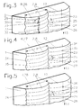
- the relief structure R is vertical irregular pattern 20 relatively expensive. That is why in 3, 4 and 5 regular patterns 26, 27, 28 shown, which also the condition of the tangential points 23rd meet, but easier to manufacture due to their periodicity are. Adjacent cylindrical lenses 2 should definitely have staggered or different periodicities.
- FIG. 3 shows a regular structure R as a relief structure Sinus pattern 26 on the surface 8 of the cylindrical lenses 2.
- a sine overlay 29 has one in the exemplary embodiment Wavelength 30 of 1 mm and an amplitude 31 of 2.26 ⁇ m.
- the reflection ratio is the measure for the residual interference light, which at the tangential points 23 that are in the sine pattern 26 on sine apices 32 and sine valleys 33 on the Surface 8 of the cylindrical lenses 2 lie, in individual Light spots with a diameter of 2.26 ⁇ m, for example split up and reflected directly to the viewer. Obviously it is a very small value compared to the value of 100% of the stray light intensity of the light band without anti-reflective structure. The very good effect of "Antireflective structure" is thus also numerically documented.
- FIG. 3 is the vertical one Offset 25 at the boundary lines 24 of the cylindrical lenses 2 recognizing that to a horizontally irregular pattern leads.
- the offset 25 is slight by shifting the sine overlay 29 on each To reach cylindrical lens 2.
- FIG. 4 shows a regular triangle pattern 27 shown.
- the triangle pattern 27 is flat rising and falling edges 34,35. This will the stray light towards the upper and lower edges 12, 13 of the lenticular screen 1, and thus from the Distracted area of perception of the viewer.
- the offset 25 is uniform in the exemplary embodiment.
- Figure 5 shows, however, a sawtooth pattern 28, which the stray light with a very long, gently rising flank 34 in just one Direction, in the exemplary embodiment in the direction of the upper one Edge 12 reflected.
- the sawtooth pattern 28 on each Cylinder lens 2 forms a relief structure R. "Roof tile character”. Otherwise also apply to the samples 27.28 the general explanations given so far.
- Which pattern 20,26,27 or 28 on the lenticular screen 1 runs depends on the respective boundary conditions from. These are among others determined by the type and Requirements of image reproduction by which to be reduced Disturbing light reflections on the lenticular screen 1 and the requirements of the viewer in sitting, standing or moving position.
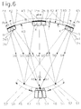
- FIG. 6 shows a projection device with a pitch width corrected lenticular screen 40 shown.
- the lenticular screen 40 has a projection screen a large screen for large-screen projection (Meter range), it has the screen thickness T and one Screen width B. Furthermore, it has a radius of curvature KR curved, the projection or viewing distance corresponds.
- the lenticular screen 40 is on its rear side 41 with a reflection layer 42 provided, for example, a club characteristic having.
- On its front 3 are the cylindrical lenses 2 with the relief structure R for the sake of clarity only partially indicated.
- In a central area 43 of the Lenticular screen 40 are cylindrical lenses 2h and 2n1 with a pitch width Pm in both edge areas 44.45 Cylinder lenses 2h and 2n1 with a pitch width Pr shown.
- the cylindrical lenses 2h are Main lenses, with the cylindrical lenses 2n1 by the first Secondary lenses. Adjacent to these, depending on the number of generating panorama diagram fields further, not shown Secondary lenses.
- the image projection takes place in the illustrated embodiment via a central arranged projector 46 and two each next to it projectors located 47.48. Depending on the number of to projecting perspectives is the number of projectors however changeable. A central zone 49 and two marginal zones 50, 51, i.e. three panoramagram fields shown.
- the projectors 46, 47, 48 are arranged along an arc 52, which is also the geometric Connection of all intersections of the reflected lens beams is (optical field curvature).
- the radius of the Circular arc 52 corresponds approximately to half the projection or Viewing distance.
- An intersection 53 is from all main lens beams 54,55,56, an intersection 57 of all first left secondary lens beams 58,59,60 and an intersection 61 of all first right Minor lens rays 62,63,64.
- For the sake of clarity 6 are only light rays 65, 66, 67 of the central projector 46 shown. Differentiate these from the main lens rays 54,55,56 only by their Orientation.
- a correction of the pitch width P with the specified parameters looks as follows (the numerically selected parameters are different from the ones shown in FIG. 6, any other numerically, technically feasible choice is possible): Number of projectors 18th Lens diameter 25 mm Screen width B 2000 mm Projection / viewing distance KR 3500 mm Screen thickness T 6.491 mm Refractive index of the lenticular screen material 1,495 Cylinder lens radius 2.158 mm Innermost pitch width Pm 0.656 mm Extreme pitch width Pr 0.630 mm Pitch width decrease 0.026 mm
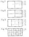
- FIGS. 7 to 10 Another problem that occurs especially when the Lenticular screen as a large-scale projection screen is formed in the following FIGS. 7 to 10 treated.
- Such projection screens are usually so large that they are easier to produce and handle are divided at least once. The individual parts are then connected accordingly.
- a projection screen 80 is without further Details shown vertically along a Center line 81 is simply divided. It therefore consists of two halves 82,83, in their structure and in their Structure in mirror image with respect to center line 81 are identical. The center line 81 is congruent with the resulting dividing seam.
- FIG. 8 shows a projection screen 84, which is double is divided symmetrically, once along a vertical Center line 85 and once along a horizontal Center line 86. There are four parts 87 to 90, the again a mirror image of the center lines 85.86 are identical.
- FIG. 9 shows a projection screen 91 which is divided into two, but along two vertical lines 92.93. These lines 92, 93 are center symmetrical arranged such that a large central part 94 and two narrow, mirror-image identical side panels 95.96 are formed. Such a division is useful, for example, when the projection screen 91 pitch-width corrected and the corrective measures are assigned at intervals.
- the middle part 94 can be a have constant pitch width P and is accordingly easy to manufacture.
- the side parts 95.96 can be identical be executed with decreasing pitch width P and require just a manufacturing template.
- Figure 10 shows a vertical and horizontal multiple split projection screen 97.
- they are all identical (constant parameterization), they can be identical to each other in sections be (parameterization at intervals) or you can all differ from each other (segment-wise parameterization), which is technically complex, however.
- the lenticular screen is made by a Molded with a negative structure.
- the die can do that entire surface structure of the lenticular screen have or only parts thereof for the production of divided Umbrellas.
- FIG. 11 shows the actual manufacturing process step upstream of the lenticular screen and although the production of a die 100 itself a required negative structure 101, which results from a negative cylindrical lens structure 102 and a negative Relief structure 103 is composed by means of a cutting stylus 104 cut into the die 100.
- This Cutting stylus 104 has a semicircular cutting edge at its end 105 on (any other meaningful form is possible).
- the negative cylindrical lens structure 102 is thus in the Way that the cutting stylus 104 with a predetermined immersion depth 106, which for complete Cutting the relief structure R must lead into the Die 100 retracts (cutting stroke) and adjacent paths 107 slightly overlapping, with for example changing Feed direction cuts.
- These movements are in of Figure 11 indicated by corresponding arrows.
- pitch width correction the distance between two adjacent cutting paths 107, for example in the direction decrease both side edges 108,109 symmetrically so that even with constant immersion depth 106, the pitch width P decreases.
- the negative relief structure 103 is produced in that the cutting stylus 1.04 during the feed for the individual webs 107 another one superimposed on the cutting stroke alternating stylus stroke (indicated in Figure 11 by a double arrow on the cutting stylus 104).
- the Frequency and the deflection of this changing stylus stroke are only determining for the training of the generating relief structure 103 (see explanations of the Figures 2 to 5). They can be constant or different from Change path to path 107.
- the deflections are moving thereby in the ⁇ m range.
- the die 100 After the manufacture of the die 100 is as described above these for taking one or more impressions Lenticular screens or parts of them ready. Most of the time Die 100 used multiple times as often as possible. In a next step, the actual one Impression process (not shown), the die 100 with a lens material which is generally a optically suitable plastic is molded. After that Lens material is cured, the die 100 must again be removed.
- Figure 12 is a way of separation from the Matrix 100 and a molded lenticular screen 111 shown.
- the die 100 If the die 100 is flexible, it can be in a simple way like a film from the lenticular screen Pull off 111 (in Figure 12 by an arrow indicated).
- the lenticular screen 111 can be so brittle or be big that he himself is difficult to remove from the matrix 100 can be removed non-destructively.
- Suitable Materials for the flexible die 100 are plastics, but also soft, springy metals like copper or brass.
- the die has on its structured surface 112 100 made of sheet brass and a silver coating better separability.
- the next process step - not shown - is Coating the back 113 (Fig. 12) of the lenticular screen 111 with a reflection layer 114 (FIG. 13).
- a reflection layer 114 in the selected embodiment is the lenticular screen 111 just part of a large projection screen. That's why there is still an assembly.
- Figure 13 shows the fully assembled projection screen 115. It consists of four identical lenticular screens 111 composed by point gluing on a flexible Pad 116 are fixed. This document 116 is in a frame 117 clamped so that the projection screen 115 has the desired curvature. After assembly, for example, there is a large 3D screen completed by using the lenticular grid Relief structure and pitch width correction a comfortable Consider very informative, autostereoscopic stand- or moving images with a particularly high image reproduction quality guaranteed.
Claims (8)
- Ecran lenticulaire (1, 40, 80, 24, 91, 97, 111) pour la perception d'images autostéréoscopiques, avec une épaisseur d'écran (T) et des lentilles cylindriques (2 ; 24, 241), développant un rayon de courbure (K) et une largeur de pas (P) sur sa face antérieure (3),
caractérisé en ce que
les lentilles cylindriques présentent sur leur surface (8) une structure en relief (R), dans laquelle les surfaces de réflexion (21, 22 ; 34, 35) sont inclinées par rapport aux axes des lentilles cylindriques, avec des dimensions qui se trouvent à une distance de l'écran lenticulaire par rapport à un observateur à la distance d'observation pour une perception d'image autostéréoscopique de l'autre côté de la limite de perceptibilité, selon un modèle prédéfini (20 ; 26, 27 ; 28) se développant verticalement, avec un décalage (25) entre les lentilles cylindriques voisines, d'une manière telle que l'on obtienne un effet antireflet. - Ecran lenticulaire selon la revendication 1
caractérisé en ce que
la largeur de pas (P) des lentilles cylindriques décroít de façon symétrique en partant du milieu (Pm) de l'écran lenticulaire vers ses deux bords verticaux latéraux (Pr). - Ecran lenticulaire selon la revendication 1 ou 2,
caractérisé en ce que
son épaisseur de lentille (T) croít de façon symétrique en allant du milieu de l'écran lenticulaire vers ses deux bords verticaux latéraux. - Ecran lenticulaire selon les revendications 2 et 3,
caractérisé en ce que
le rayon de courbure (K) des lentilles cylindriques croít de façon symétrique en partant du milieu de l'écran lenticulaire vers ses deux bords verticaux latéraux. - Ecran lenticulaire selon la revendication 2,
caractérisé en ce que
son épaisseur d'écran (T) est constante. - Ecran lenticulaire selon l'une des revendications 1 à 5,
caractérisé en ce que
celui-ci présente, comme écran de projection (80, 84, 91, 97, 115) pour la projection de grandes images une grande diagonale de l'image à peu près de l'ordre du mètre. - Ecran lenticulaire selon l'une des revendications 1 à 6,
caractérisé en ce que
celui-ci est partagé au moins simplement (22, 23 ; 87-90 94-96 ; 98) - Ecran lenticulaire selon la revendication 7,
caractérisé en ce que
des joints de partage horizontales et/ou verticales (81 ; 85, 86 ; 92, 93) sont disposés sur l'écran lenticulaire (80, 84, 91, 97, 115) de façon symétrique les unes par rapport aux autres.
Applications Claiming Priority (2)
| Application Number | Priority Date | Filing Date | Title |
|---|---|---|---|
| DE4042313 | 1990-12-30 | ||
| DE4042313 | 1990-12-30 |
Publications (3)
| Publication Number | Publication Date |
|---|---|
| EP0493863A2 EP0493863A2 (fr) | 1992-07-08 |
| EP0493863A3 EP0493863A3 (en) | 1993-03-24 |
| EP0493863B1 true EP0493863B1 (fr) | 1998-03-11 |
Family
ID=6421740
Family Applications (1)
| Application Number | Title | Priority Date | Filing Date |
|---|---|---|---|
| EP91250341A Expired - Lifetime EP0493863B1 (fr) | 1990-12-30 | 1991-12-23 | Ecran lenticulaire pour la perception d'images autostéréoscopiques |
Country Status (2)
| Country | Link |
|---|---|
| EP (1) | EP0493863B1 (fr) |
| DE (2) | DE4143121A1 (fr) |
Cited By (1)
| Publication number | Priority date | Publication date | Assignee | Title |
|---|---|---|---|---|
| US8081368B2 (en) | 2007-03-29 | 2011-12-20 | Bose Corporation | Selective absorbing |
Families Citing this family (8)
| Publication number | Priority date | Publication date | Assignee | Title |
|---|---|---|---|---|
| DE4447448A1 (de) * | 1994-12-29 | 1996-07-04 | Seebeck Norbert Dipl Ing | Dreidimensionale Bildwiedergabevorrichtung mit einem Trennwändenlinsensystem |
| AUPO884297A0 (en) * | 1997-08-27 | 1997-09-18 | Orme, Gregory Michael | Imaging devices |
| DE19831713C2 (de) * | 1998-07-15 | 2002-06-20 | Siegbert Hentschke | Positionsadaptiver 3D-Raster-Monitor (PARM) |
| US6847483B2 (en) * | 2001-12-21 | 2005-01-25 | Bose Corporation | Selective reflecting |
| US7710645B2 (en) | 2007-06-29 | 2010-05-04 | Bose Corporation | Selective reflecting for laser projector |
| EP2471268B1 (fr) | 2009-08-25 | 2014-10-08 | Dolby Laboratories Licensing Corporation | Système d'affichage tridimensionnel |
| CN105204281B (zh) * | 2014-06-20 | 2017-06-06 | 台达电子工业股份有限公司 | 投影屏幕及应用其的投影系统 |
| DE112019002671T5 (de) * | 2018-05-25 | 2021-04-22 | AGC Inc. | Bildprojektionsstruktur, verfahren zu deren herstellung und bildanzeigesystem |
Citations (1)
| Publication number | Priority date | Publication date | Assignee | Title |
|---|---|---|---|---|
| US4013465A (en) * | 1973-05-10 | 1977-03-22 | Secretary Of State For Defence In Her Britannic Majesty's Government Of The United Kingdom Of Great Britain And Northern Ireland | Reducing the reflectance of surfaces to radiation |
Family Cites Families (3)
| Publication number | Priority date | Publication date | Assignee | Title |
|---|---|---|---|---|
| US1867199A (en) * | 1930-03-11 | 1932-07-12 | Wildhaber Ernest | Projection screen |
| DE3529819C2 (de) * | 1985-08-16 | 1994-11-03 | Hertz Inst Heinrich | Projektionseinrichtung zum Erzeugen autostereoskopisch betrachtbarer Bilder |
| DE3921061A1 (de) * | 1989-06-23 | 1991-01-03 | Hertz Inst Heinrich | Wiedergabeeinrichtung fuer dreidimensionale wahrnehmung von bildern |
-
1991
- 1991-12-23 EP EP91250341A patent/EP0493863B1/fr not_active Expired - Lifetime
- 1991-12-23 DE DE4143121A patent/DE4143121A1/de not_active Withdrawn
- 1991-12-23 DE DE59108951T patent/DE59108951D1/de not_active Expired - Fee Related
Patent Citations (1)
| Publication number | Priority date | Publication date | Assignee | Title |
|---|---|---|---|---|
| US4013465A (en) * | 1973-05-10 | 1977-03-22 | Secretary Of State For Defence In Her Britannic Majesty's Government Of The United Kingdom Of Great Britain And Northern Ireland | Reducing the reflectance of surfaces to radiation |
Cited By (1)
| Publication number | Priority date | Publication date | Assignee | Title |
|---|---|---|---|---|
| US8081368B2 (en) | 2007-03-29 | 2011-12-20 | Bose Corporation | Selective absorbing |
Also Published As
| Publication number | Publication date |
|---|---|
| DE4143121A1 (de) | 1992-07-02 |
| EP0493863A3 (en) | 1993-03-24 |
| DE59108951D1 (de) | 1998-04-16 |
| EP0493863A2 (fr) | 1992-07-08 |
Similar Documents
| Publication | Publication Date | Title |
|---|---|---|
| DE69930821T2 (de) | Fresnel-Linsenfolie | |
| DE2727642C3 (de) | Vorrichtung zum Projizieren einer Vielzahl zweidimensionaler Ansichten zur Herstellung von Parallaxstereogrammen | |
| DE1597521B2 (de) | Verfahren zur Erzeugung eines einen räumlichen Bildeindruck vermittelnden Integralbildes | |
| DE102011083940A1 (de) | Gedruckte längliche Linsen für das Drucken von länglichen Linsenstrukturen | |
| DE2056605A1 (de) | Verfahren und Vorrichtung zum Simulieren von Bewegung | |
| DE4312918A1 (de) | Wiedergabeeinrichtung | |
| WO1995028664A1 (fr) | Module de retroprojection | |
| EP0493863B1 (fr) | Ecran lenticulaire pour la perception d'images autostéréoscopiques | |
| DE69827538T2 (de) | Durchlichtbildanzeigevorrichtung | |
| DE2248873B2 (de) | Stereo-Bildwiedergabesystem | |
| EP1895782A2 (fr) | Dispositif d'affichage autostéréoscopique | |
| DE19750141C2 (de) | Abblendauswahlvorrichtung für Stereobildrahmen | |
| DE2012191C3 (de) | Verfahren und Vorrichtung zur Herstellung von Projektionsflächen beliebiger Indicatrix | |
| DE2655527B1 (de) | Projektionsschirm und Verfahren zu dessen Herstellung | |
| DE60026389T2 (de) | Rückprojektionsschirm | |
| DE1935422A1 (de) | Vorrichtung zum Verzieren gezogener Dosen | |
| WO1999044091A1 (fr) | Unite de reproduction d'images | |
| EP2122415B1 (fr) | Dispositif de reproduction d'image autostéréoscopique pour produire une image stéréo réelle flottante | |
| DE3700525A1 (de) | Projektionseinrichtung fuer parallax-panoramagramme | |
| DE60002335T2 (de) | Zusammengesetzte linse zur verwendung in linsenanordnungen | |
| DE3425913A1 (de) | Verfahren und vorrichtung zur ermittlung der abmessungen eines gegenstandes auf photographischem wege | |
| DE2537547C3 (de) | Stufenlinsenkondensor geringer Blendung | |
| DE1446839C3 (de) | Parallaxstereogrammanordnung | |
| DE69817028T2 (de) | Projektionsfernsehgeräte mit holographischen bildschirmen und aufeinandergestapelten elementen | |
| WO1996027144A1 (fr) | Systeme d'ecran autostereoscopique |
Legal Events
| Date | Code | Title | Description |
|---|---|---|---|
| PUAI | Public reference made under article 153(3) epc to a published international application that has entered the european phase |
Free format text: ORIGINAL CODE: 0009012 |
|
| AK | Designated contracting states |
Kind code of ref document: A2 Designated state(s): DE FR GB NL |
|
| PUAL | Search report despatched |
Free format text: ORIGINAL CODE: 0009013 |
|
| AK | Designated contracting states |
Kind code of ref document: A3 Designated state(s): DE FR GB NL |
|
| 17P | Request for examination filed |
Effective date: 19930429 |
|
| 17Q | First examination report despatched |
Effective date: 19950504 |
|
| GRAG | Despatch of communication of intention to grant |
Free format text: ORIGINAL CODE: EPIDOS AGRA |
|
| GRAG | Despatch of communication of intention to grant |
Free format text: ORIGINAL CODE: EPIDOS AGRA |
|
| GRAH | Despatch of communication of intention to grant a patent |
Free format text: ORIGINAL CODE: EPIDOS IGRA |
|
| GRAH | Despatch of communication of intention to grant a patent |
Free format text: ORIGINAL CODE: EPIDOS IGRA |
|
| GRAA | (expected) grant |
Free format text: ORIGINAL CODE: 0009210 |
|
| AK | Designated contracting states |
Kind code of ref document: B1 Designated state(s): DE FR GB NL |
|
| REF | Corresponds to: |
Ref document number: 59108951 Country of ref document: DE Date of ref document: 19980416 |
|
| GBT | Gb: translation of ep patent filed (gb section 77(6)(a)/1977) |
Effective date: 19980605 |
|
| ET | Fr: translation filed | ||
| PLBE | No opposition filed within time limit |
Free format text: ORIGINAL CODE: 0009261 |
|
| STAA | Information on the status of an ep patent application or granted ep patent |
Free format text: STATUS: NO OPPOSITION FILED WITHIN TIME LIMIT |
|
| 26N | No opposition filed | ||
| PGFP | Annual fee paid to national office [announced via postgrant information from national office to epo] |
Ref country code: NL Payment date: 20011221 Year of fee payment: 11 |
|
| REG | Reference to a national code |
Ref country code: GB Ref legal event code: IF02 |
|
| PG25 | Lapsed in a contracting state [announced via postgrant information from national office to epo] |
Ref country code: NL Free format text: LAPSE BECAUSE OF NON-PAYMENT OF DUE FEES Effective date: 20030701 |
|
| NLV4 | Nl: lapsed or anulled due to non-payment of the annual fee |
Effective date: 20030701 |
|
| REG | Reference to a national code |
Ref country code: GB Ref legal event code: 732E |
|
| REG | Reference to a national code |
Ref country code: FR Ref legal event code: TP |
|
| PGFP | Annual fee paid to national office [announced via postgrant information from national office to epo] |
Ref country code: DE Payment date: 20061114 Year of fee payment: 16 |
|
| PGFP | Annual fee paid to national office [announced via postgrant information from national office to epo] |
Ref country code: GB Payment date: 20061214 Year of fee payment: 16 |
|
| PGFP | Annual fee paid to national office [announced via postgrant information from national office to epo] |
Ref country code: FR Payment date: 20061228 Year of fee payment: 16 |
|
| GBPC | Gb: european patent ceased through non-payment of renewal fee |
Effective date: 20071223 |
|
| PG25 | Lapsed in a contracting state [announced via postgrant information from national office to epo] |
Ref country code: DE Free format text: LAPSE BECAUSE OF NON-PAYMENT OF DUE FEES Effective date: 20080701 |
|
| REG | Reference to a national code |
Ref country code: FR Ref legal event code: ST Effective date: 20081020 |
|
| PG25 | Lapsed in a contracting state [announced via postgrant information from national office to epo] |
Ref country code: GB Free format text: LAPSE BECAUSE OF NON-PAYMENT OF DUE FEES Effective date: 20071223 |
|
| PG25 | Lapsed in a contracting state [announced via postgrant information from national office to epo] |
Ref country code: FR Free format text: LAPSE BECAUSE OF NON-PAYMENT OF DUE FEES Effective date: 20071231 |