EP0492109A1 - Hydraulic brake system for vehicles - Google Patents
Hydraulic brake system for vehicles Download PDFInfo
- Publication number
- EP0492109A1 EP0492109A1 EP91119219A EP91119219A EP0492109A1 EP 0492109 A1 EP0492109 A1 EP 0492109A1 EP 91119219 A EP91119219 A EP 91119219A EP 91119219 A EP91119219 A EP 91119219A EP 0492109 A1 EP0492109 A1 EP 0492109A1
- Authority
- EP
- European Patent Office
- Prior art keywords
- valve
- pressure
- shut
- armature
- brake system
- Prior art date
- Legal status (The legal status is an assumption and is not a legal conclusion. Google has not performed a legal analysis and makes no representation as to the accuracy of the status listed.)
- Granted
Links
- 230000006835 compression Effects 0.000 claims abstract description 21
- 238000007906 compression Methods 0.000 claims abstract description 21
- 238000003780 insertion Methods 0.000 description 3
- 230000037431 insertion Effects 0.000 description 3
- 238000005299 abrasion Methods 0.000 description 2
- 238000010586 diagram Methods 0.000 description 2
- 230000004323 axial length Effects 0.000 description 1
- 238000011161 development Methods 0.000 description 1
- 230000018109 developmental process Effects 0.000 description 1
- 230000000694 effects Effects 0.000 description 1
- 239000002184 metal Substances 0.000 description 1
- 230000036316 preload Effects 0.000 description 1
- 238000007789 sealing Methods 0.000 description 1
Images

Classifications
-
- B—PERFORMING OPERATIONS; TRANSPORTING
- B60—VEHICLES IN GENERAL
- B60T—VEHICLE BRAKE CONTROL SYSTEMS OR PARTS THEREOF; BRAKE CONTROL SYSTEMS OR PARTS THEREOF, IN GENERAL; ARRANGEMENT OF BRAKING ELEMENTS ON VEHICLES IN GENERAL; PORTABLE DEVICES FOR PREVENTING UNWANTED MOVEMENT OF VEHICLES; VEHICLE MODIFICATIONS TO FACILITATE COOLING OF BRAKES
- B60T8/00—Arrangements for adjusting wheel-braking force to meet varying vehicular or ground-surface conditions, e.g. limiting or varying distribution of braking force
- B60T8/32—Arrangements for adjusting wheel-braking force to meet varying vehicular or ground-surface conditions, e.g. limiting or varying distribution of braking force responsive to a speed condition, e.g. acceleration or deceleration
- B60T8/34—Arrangements for adjusting wheel-braking force to meet varying vehicular or ground-surface conditions, e.g. limiting or varying distribution of braking force responsive to a speed condition, e.g. acceleration or deceleration having a fluid pressure regulator responsive to a speed condition
- B60T8/42—Arrangements for adjusting wheel-braking force to meet varying vehicular or ground-surface conditions, e.g. limiting or varying distribution of braking force responsive to a speed condition, e.g. acceleration or deceleration having a fluid pressure regulator responsive to a speed condition having expanding chambers for controlling pressure, i.e. closed systems
- B60T8/4275—Pump-back systems
- B60T8/4291—Pump-back systems having means to reduce or eliminate pedal kick-back
-
- B—PERFORMING OPERATIONS; TRANSPORTING
- B60—VEHICLES IN GENERAL
- B60T—VEHICLE BRAKE CONTROL SYSTEMS OR PARTS THEREOF; BRAKE CONTROL SYSTEMS OR PARTS THEREOF, IN GENERAL; ARRANGEMENT OF BRAKING ELEMENTS ON VEHICLES IN GENERAL; PORTABLE DEVICES FOR PREVENTING UNWANTED MOVEMENT OF VEHICLES; VEHICLE MODIFICATIONS TO FACILITATE COOLING OF BRAKES
- B60T13/00—Transmitting braking action from initiating means to ultimate brake actuator with power assistance or drive; Brake systems incorporating such transmitting means, e.g. air-pressure brake systems
- B60T13/10—Transmitting braking action from initiating means to ultimate brake actuator with power assistance or drive; Brake systems incorporating such transmitting means, e.g. air-pressure brake systems with fluid assistance, drive, or release
- B60T13/66—Electrical control in fluid-pressure brake systems
- B60T13/68—Electrical control in fluid-pressure brake systems by electrically-controlled valves
- B60T13/686—Electrical control in fluid-pressure brake systems by electrically-controlled valves in hydraulic systems or parts thereof
-
- B—PERFORMING OPERATIONS; TRANSPORTING
- B60—VEHICLES IN GENERAL
- B60T—VEHICLE BRAKE CONTROL SYSTEMS OR PARTS THEREOF; BRAKE CONTROL SYSTEMS OR PARTS THEREOF, IN GENERAL; ARRANGEMENT OF BRAKING ELEMENTS ON VEHICLES IN GENERAL; PORTABLE DEVICES FOR PREVENTING UNWANTED MOVEMENT OF VEHICLES; VEHICLE MODIFICATIONS TO FACILITATE COOLING OF BRAKES
- B60T8/00—Arrangements for adjusting wheel-braking force to meet varying vehicular or ground-surface conditions, e.g. limiting or varying distribution of braking force
- B60T8/32—Arrangements for adjusting wheel-braking force to meet varying vehicular or ground-surface conditions, e.g. limiting or varying distribution of braking force responsive to a speed condition, e.g. acceleration or deceleration
- B60T8/34—Arrangements for adjusting wheel-braking force to meet varying vehicular or ground-surface conditions, e.g. limiting or varying distribution of braking force responsive to a speed condition, e.g. acceleration or deceleration having a fluid pressure regulator responsive to a speed condition
- B60T8/36—Arrangements for adjusting wheel-braking force to meet varying vehicular or ground-surface conditions, e.g. limiting or varying distribution of braking force responsive to a speed condition, e.g. acceleration or deceleration having a fluid pressure regulator responsive to a speed condition including a pilot valve responding to an electromagnetic force
- B60T8/3615—Electromagnetic valves specially adapted for anti-lock brake and traction control systems
- B60T8/363—Electromagnetic valves specially adapted for anti-lock brake and traction control systems in hydraulic systems
- B60T8/365—Electromagnetic valves specially adapted for anti-lock brake and traction control systems in hydraulic systems combining a plurality of functions in one unit, e.g. pressure relief
-
- B—PERFORMING OPERATIONS; TRANSPORTING
- B60—VEHICLES IN GENERAL
- B60T—VEHICLE BRAKE CONTROL SYSTEMS OR PARTS THEREOF; BRAKE CONTROL SYSTEMS OR PARTS THEREOF, IN GENERAL; ARRANGEMENT OF BRAKING ELEMENTS ON VEHICLES IN GENERAL; PORTABLE DEVICES FOR PREVENTING UNWANTED MOVEMENT OF VEHICLES; VEHICLE MODIFICATIONS TO FACILITATE COOLING OF BRAKES
- B60T8/00—Arrangements for adjusting wheel-braking force to meet varying vehicular or ground-surface conditions, e.g. limiting or varying distribution of braking force
- B60T8/32—Arrangements for adjusting wheel-braking force to meet varying vehicular or ground-surface conditions, e.g. limiting or varying distribution of braking force responsive to a speed condition, e.g. acceleration or deceleration
- B60T8/34—Arrangements for adjusting wheel-braking force to meet varying vehicular or ground-surface conditions, e.g. limiting or varying distribution of braking force responsive to a speed condition, e.g. acceleration or deceleration having a fluid pressure regulator responsive to a speed condition
- B60T8/48—Arrangements for adjusting wheel-braking force to meet varying vehicular or ground-surface conditions, e.g. limiting or varying distribution of braking force responsive to a speed condition, e.g. acceleration or deceleration having a fluid pressure regulator responsive to a speed condition connecting the brake actuator to an alternative or additional source of fluid pressure, e.g. traction control systems
- B60T8/4809—Traction control, stability control, using both the wheel brakes and other automatic braking systems
- B60T8/4827—Traction control, stability control, using both the wheel brakes and other automatic braking systems in hydraulic brake systems
- B60T8/4863—Traction control, stability control, using both the wheel brakes and other automatic braking systems in hydraulic brake systems closed systems
- B60T8/4872—Traction control, stability control, using both the wheel brakes and other automatic braking systems in hydraulic brake systems closed systems pump-back systems
-
- F—MECHANICAL ENGINEERING; LIGHTING; HEATING; WEAPONS; BLASTING
- F16—ENGINEERING ELEMENTS AND UNITS; GENERAL MEASURES FOR PRODUCING AND MAINTAINING EFFECTIVE FUNCTIONING OF MACHINES OR INSTALLATIONS; THERMAL INSULATION IN GENERAL
- F16K—VALVES; TAPS; COCKS; ACTUATING-FLOATS; DEVICES FOR VENTING OR AERATING
- F16K17/00—Safety valves; Equalising valves, e.g. pressure relief valves
- F16K17/02—Safety valves; Equalising valves, e.g. pressure relief valves opening on surplus pressure on one side; closing on insufficient pressure on one side
- F16K17/04—Safety valves; Equalising valves, e.g. pressure relief valves opening on surplus pressure on one side; closing on insufficient pressure on one side spring-loaded
- F16K17/048—Safety valves; Equalising valves, e.g. pressure relief valves opening on surplus pressure on one side; closing on insufficient pressure on one side spring-loaded combined with other safety valves, or with pressure control devices
-
- F—MECHANICAL ENGINEERING; LIGHTING; HEATING; WEAPONS; BLASTING
- F16—ENGINEERING ELEMENTS AND UNITS; GENERAL MEASURES FOR PRODUCING AND MAINTAINING EFFECTIVE FUNCTIONING OF MACHINES OR INSTALLATIONS; THERMAL INSULATION IN GENERAL
- F16K—VALVES; TAPS; COCKS; ACTUATING-FLOATS; DEVICES FOR VENTING OR AERATING
- F16K31/00—Actuating devices; Operating means; Releasing devices
- F16K31/02—Actuating devices; Operating means; Releasing devices electric; magnetic
- F16K31/06—Actuating devices; Operating means; Releasing devices electric; magnetic using a magnet, e.g. diaphragm valves, cutting off by means of a liquid
- F16K31/0644—One-way valve
- F16K31/0655—Lift valves
-
- Y—GENERAL TAGGING OF NEW TECHNOLOGICAL DEVELOPMENTS; GENERAL TAGGING OF CROSS-SECTIONAL TECHNOLOGIES SPANNING OVER SEVERAL SECTIONS OF THE IPC; TECHNICAL SUBJECTS COVERED BY FORMER USPC CROSS-REFERENCE ART COLLECTIONS [XRACs] AND DIGESTS
- Y10—TECHNICAL SUBJECTS COVERED BY FORMER USPC
- Y10S—TECHNICAL SUBJECTS COVERED BY FORMER USPC CROSS-REFERENCE ART COLLECTIONS [XRACs] AND DIGESTS
- Y10S303/00—Fluid-pressure and analogous brake systems
- Y10S303/90—ABS throttle control
-
- Y—GENERAL TAGGING OF NEW TECHNOLOGICAL DEVELOPMENTS; GENERAL TAGGING OF CROSS-SECTIONAL TECHNOLOGIES SPANNING OVER SEVERAL SECTIONS OF THE IPC; TECHNICAL SUBJECTS COVERED BY FORMER USPC CROSS-REFERENCE ART COLLECTIONS [XRACs] AND DIGESTS
- Y10—TECHNICAL SUBJECTS COVERED BY FORMER USPC
- Y10S—TECHNICAL SUBJECTS COVERED BY FORMER USPC CROSS-REFERENCE ART COLLECTIONS [XRACs] AND DIGESTS
- Y10S303/00—Fluid-pressure and analogous brake systems
- Y10S303/901—ABS check valve detail
Definitions
- the invention relates to a hydraulic brake system with an anti-lock and traction control system, in particular for motor vehicles, according to the preamble of the main claim.
- a brake system has already been proposed (DE patent application P 40 34 113.5) in which the shut-off valve and the pressure relief valve are structurally independent of one another.
- the pressure relief valve arranged parallel to the shut-off valve becomes effective when the consumer (wheel brake) cannot remove the pressure medium fed into the line (brake line) from the pressure source (high-pressure pump) when the shut-off valve is closed.
- the pressure relief valve opens at a predetermined response pressure, so that a part of the pressure medium can flow out to the pressure generator (master brake cylinder).
- the pressure relief valve designed as a seat valve performs a very small stroke.
- This stroke is not sufficient to continuously close the pressure limiting valve for foreign bodies carried by the pressure medium, such as seal abrasion, metal abrasion and the like make, that is, the foreign bodies are deposited on the valve seat and impair the function of the pressure relief valve.
- the brake system according to the invention with the characterizing features of the main claim has the advantage that the seat valve formed by the valve seat and closing member of the shut-off valve in the valve closing position also takes over the function of the pressure relief valve when the consumer-side pressure exceeds the response pressure.
- the closing member only performs a very small stroke when limiting the pressure.
- the shut-off valve is switched to its open position, in which a pressure-limiting function is not required, the closing member carries out a much larger stroke.
- the valve is therefore passable for foreign bodies in the open position. Foreign objects attached to the poppet valve are now rinsed out. This increases the functional reliability of the brake system.
- the space and cost savings achieved with the design according to the invention are also advantageous.
- the closing force generated by the compression spring is less than the magnetic force acting on the armature, noise is reduced and wear on the valve seat is reduced.
- the measure specified in claim 2 is advantageous in that, despite the insertion of a compression spring between the armature and the tappet, an increase in the axial length of the shut-off valve is avoided.
- the compression spring for the pressure-limiting function is activated with simple means in the valve closing position. In the open position, however, the force flow of the compression spring is closed via the armature, so that the major part of the opening and closing stroke of the armature is free of the force of the compression spring.
- the measure disclosed in claim 4 allows the prestressing force of the compression spring inserted into the blind hole to be set in a simple manner.
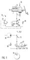
- FIG. 1 shows a part of a circuit diagram of a hydraulic brake system with a valve unit consisting of a shut-off valve and a pressure relief valve
- FIG. 2 shows a longitudinal section through the valve unit with a structural design.
- FIG. 1 shows only part of a hydraulic brake system 10 with an anti-lock and traction control device.
- the brake system 10 has a pedal-actuated, multi-circuit master brake cylinder 11 as a pressure generator with a pressure medium reservoir 12. At least one line 13 extends from the master brake cylinder 11 as a brake line to at least one wheel brake 14 as a consumer.
- a shut-off valve 15 in the form of a 2/2-way valve is arranged in line 13.
- the shut-off valve 15 has a through position 15a that can be generated by spring actuation, in which Amounts of pressure medium can be shifted between the master brake cylinder 11 and the wheel brake 14.
- the shut-off valve 15 also has a closed position 15b that can be generated by electromagnetic actuation. In this closed position 15b, the shut-off valve 15 separates a pressure medium flow between a line section 13.1 on the master cylinder side and a line section 13.2 of the line 13 on the wheel brake side.
- a check valve 18 is arranged parallel to the shut-off valve 15 and allows pressure medium to flow from the master brake cylinder 1 to the wheel brake 14 bypassing the shut-off valve.
- a pressure relief valve 21 is connected in parallel to the shut-off valve 15.
- the pressure limiting valve 21 is able to open against spring force when a predetermined response pressure is exceeded, so that pressure medium quantities can be controlled from the line section 13.2 to the line section 13.1 and thus to the master brake cylinder 11.
- the pressure limiting valve 21 therefore prevents an impermissibly high pressure rise in the area of the brake system 10 on the wheel brake side.
- valve unit 24 The shut-off valve 15 and the pressure relief valve 21 are, as indicated by dash-dotted lines in FIG. 1, structurally and functionally combined to form a valve unit 24. This valve unit 24 is described in detail later.
- a pressure control valve arrangement 27 is also arranged in the line 13 as an element of the anti-lock and traction control device.
- the pressure control valve arrangement 27 has a position 27a which can be generated by spring actuation and in which the line section 13.2 to the wheel brake 14 is continuous.
- the pressure control valve arrangement 27 has an adjustable by solenoid actuation Position 27b for maintaining pressure in the wheel brake 14, in which the line section 13.2 to the wheel brake is interrupted.
- a non-return valve 28 is arranged parallel to the pressure control valve arrangement 27, with which pressure medium flow from the wheel brake 14 to the master brake cylinder 11 is possible bypassing the pressure control valve arrangement.
- a pressure source 30 in the form of a high-pressure pump is connected to line section 13.2.
- the pressure source 30 can feed pressure medium into the line 13. Since the pressure medium in the positions 27b and 27c of the pressure control valve arrangement 27 cannot be absorbed by the wheel brake 14, the pressure limiting valve 21 opens when its response pressure is exceeded and controls the pressure medium to the master brake cylinder 11.
- the valve unit 24 has the structure shown in FIG. 2:
- a valve housing 33 has a stepped longitudinal bore 34, in the lower region of which a sleeve 35 with a valve seat 36 is pressed. At its lower end, the longitudinal bore 34 is covered by a disc filter 37. In the upper section of the longitudinal bore 34 extends a plunger 38 which carries a closing member 39 in the form of a ball on the valve seat side. The valve seat 36 and the closing member 39 form a seat valve. This is shown in the drawing in its through position, which is produced by a return spring 40 which is supported on the one hand on the valve seat sleeve 35 and on the other hand on the tappet 38.
- the valve housing 33 has a transverse bore 43 which opens into the longitudinal bore 34 in the region of the valve seat 36.
- the transverse bore 43 is covered by a sleeve filter 44 encompassing the valve housing 33.
- the receiving bore 48 is closed on the mouth side by a sealing ring 50 seated on the valve housing 33 in a pressure-tight manner.
- a bore 51 opens, at the lower end of the valve housing 33 a bore 52 opens into the receiving bore 48 of the housing block 49.
- the bore 51 corresponds to the line section 13.1 coming from the master brake cylinder 11, the bore 52 corresponds to the line section 13.2 leading to the wheel brake 14.
- a sleeve 53 accommodated on the valve housing 33 between the two bores 51 and 52 embodies the check valve 18 in cooperation with the receiving bore 48.
- the flange 47 of the valve unit 24 carries an electrical coil 56 which is gripped by a cup-shaped housing jacket 57 connected to the flange 47.
- An armature guide sleeve 58 connected to the valve housing 33 in a pressure-tight manner extends within the coil 56.
- An armature 59 is accommodated in the armature guide sleeve 58 so as to be longitudinally movable.
- This has a blind hole 60 running coaxially with the tappet 38.
- the depth of the blind hole 60 open against the tappet 38 is determined by a press-in bolt 61 running coaxially in the armature 59.
- the blind bore 60 has a bore step 62 that narrows its cross section.
- the compression spring 64 engages on the one hand on the press-in bolt 61 and on the other hand on the disk 63, which in turn is supported on the bore step 62 in the drawn through position of the seat valve 36, 39.
- the preload of the compression spring 64 can be adjusted by the insertion depth of the insertion bolt 61 in the armature 59.
- the disk 63 serves as an intermediate member between the compression spring 64 and the plunger 38 which acts on the disk under the action of the return spring 40.
- the biasing force of the compression spring 64 is greater than that of the return spring 40.
- the compression spring 64 exerts an axial force on the plunger 38 at the end of the armature stroke.
- This force transmitted by the plunger 38 to the closing member 39 is lower than the magnetic force of the armature 59 and acts as a closing force which is matched to the response pressure of the pressure limiting valve 21.
- valve unit 24 When the closing member 39 engages the valve seat 36, the valve unit 24 performs the function of the shut-off valve 15 in its closed position 15b and the function of the pressure limiting valve 21.
Abstract
Description
Die Erfindung geht aus von einer hydraulischen Bremsanlage mit einer Blockierschutz- und Antriebsschlupfregeleinrichtung, insbesondere für Kraftfahrzeuge, nach der Gattung des Hauptanspruchs.The invention relates to a hydraulic brake system with an anti-lock and traction control system, in particular for motor vehicles, according to the preamble of the main claim.
Es ist schon eine Bremsanlage vorgeschlagen worden (DE-Patentanmeldung P 40 34 113.5), bei welcher das Absperrventil und das Druckbegrenzungsventil baulich voneinander unabhängig ausgebildet sind. Das parallel zum Absperrventil angeordnete Druckbegrenzungsventil wird wirksam, wenn bei geschlossenem Absperrventil der Verbraucher (Radbremse) das von der Druckquelle (Hochdruckpumpe) in die Leitung (Bremsleitung) eingespeiste Druckmittel nicht abnehmen kann. Um Schäden durch einen unzulässig hohen Druckanstieg in der Leitung und in der Druckquelle zu verhindern, öffnet das Druckbegrenzungsventil bei einem vorbestimmten Ansprechdruck, so daß eine Teilmenge des Druckmittels zum Druckerzeuger (Hauptbremszylinder) abströmen kann. Dabei führt das als Sitzventil ausgebildete Druckbegrenzungsventil einen sehr kleinen Hub aus. Dieser Hub ist nicht ausreichend, um das Druckbegrenzungsventil für vom Druckmittel mitgeführte Fremdkörper, wie Dichtungsabrieb, Metallabrieb und dergleichen, durchgängig zu machen, d. h. die Fremdkörper lagern sich am Ventilsitz ab und beeinträchtigen die Funktion des Druckbegrenzungsventils.A brake system has already been proposed (DE
Die erfindungsgemäße Bremsanlage mit den kennzeichnenden Merkmalen des Hauptanspruchs hat demgegenüber den Vorteil, daß das vom Ventilsitz und Schließglied gebildete Sitzventil des Absperrventils in der Ventilschließstellung die Funktion des Druckbegrenzungsventils mit übernimmt, wenn der verbraucherseitige Druck den Ansprechdruck überschreitet. Zwar führt das Schließglied beim Begrenzen des Druckes nur einen sehr kleinen Hub aus. Beim Schalten des Absperrventils in seine Durchgangsstellung, in welcher eine druckbegrenzende Funktion nicht erforderlich ist, führt das Schließglied jedoch einen sehr viel größeren Hub aus. Das Ventil ist somit in der Durchgangsstellung für Fremdkörper durchgängig. Bei der Druckbegrenzungsfunktion am Sitzventil angelagerte Fremdkörper werden jetzt ausgespült. Die Funktionssicherheit der Bremsanlage wird dadurch erhöht. Weiterhin ist die mit der erfindungsgemäßen Gestaltung erzielte Raum- und Kosteneinsparung ebenfalls von Vorteil. Da die von der Druckfeder erzeugte Schließkraft geringer ist als die auf den Anker wirkende Magnetkraft, wird darüber hinaus eine Geräuschminderung sowie eine Reduzierung des Verschleißes am Ventilsitz erzielt.The brake system according to the invention with the characterizing features of the main claim has the advantage that the seat valve formed by the valve seat and closing member of the shut-off valve in the valve closing position also takes over the function of the pressure relief valve when the consumer-side pressure exceeds the response pressure. The closing member only performs a very small stroke when limiting the pressure. When the shut-off valve is switched to its open position, in which a pressure-limiting function is not required, the closing member carries out a much larger stroke. The valve is therefore passable for foreign bodies in the open position. Foreign objects attached to the poppet valve are now rinsed out. This increases the functional reliability of the brake system. Furthermore, the space and cost savings achieved with the design according to the invention are also advantageous. In addition, since the closing force generated by the compression spring is less than the magnetic force acting on the armature, noise is reduced and wear on the valve seat is reduced.
Durch die in den Unteransprüchen aufgeführten Maßnahmen sind vorteilhafte Weiterbildungen und Verbesserungen der im Hauptanspruch angegebenen Bremsanlage möglich.Advantageous further developments and improvements of the brake system specified in the main claim are possible through the measures listed in the subclaims.
Die im Anspruch 2 angegebene Maßnahme ist insofern vorteilhaft, als trotz des Einfügens einer Druckfeder zwischen den Anker und den Stößel eine Vergrößerung der axialen Baulänge des Absperrventils vermieden wird.The measure specified in claim 2 is advantageous in that, despite the insertion of a compression spring between the armature and the tappet, an increase in the axial length of the shut-off valve is avoided.
Mit der im Anspruch 3 gekennzeichneten Ausgestaltung wird mit einfachen Mitteln in der Ventilschließstellung ein Wirksamwerden der Druckfeder für die Druckbegrenzungsfunktion erzielt. In der Durchgangsstellung ist dagegen der Kraftfluß der Druckfeder über den Anker geschlossen, so daß der überwiegende Teil des Öffnungs- und Schließhubes des Ankers frei von der Kraft der Druckfeder ist.With the embodiment characterized in claim 3, the compression spring for the pressure-limiting function is activated with simple means in the valve closing position. In the open position, however, the force flow of the compression spring is closed via the armature, so that the major part of the opening and closing stroke of the armature is free of the force of the compression spring.
Die im Anspruch 4 offenbarte Maßnahme erlaubt auf einfache Weise die Einstellung der Vorspannkraft der in die Sacklochbohrung eingefügten Druckfeder.The measure disclosed in claim 4 allows the prestressing force of the compression spring inserted into the blind hole to be set in a simple manner.
Ein Ausführungsbeispiel der Erfindung ist in der Zeichnung vereinfacht dargestellt und in der nachfolgenden Beschreibung näher erläutert. Es zeigen Figur 1 einen Teil eines Schaltschemas einer hydraulischen Bremsanlage mit einer aus Absperrventil und Druckbegrenzungsventil bestehenden Ventileinheit und Figur 2 einen Längsschnitt durch die konstruktiv ausgestaltete Ventileinheit.An embodiment of the invention is shown in simplified form in the drawing and explained in more detail in the following description. FIG. 1 shows a part of a circuit diagram of a hydraulic brake system with a valve unit consisting of a shut-off valve and a pressure relief valve, and FIG. 2 shows a longitudinal section through the valve unit with a structural design.
Das in Figur 1 dargestellte Schaltschema gibt nur einen Teil einer hydraulischen Bremsanlage 10 mit einer Blockierschutz- und Antriebsschlupfregeleinrichtung wieder.The circuit diagram shown in Figure 1 shows only part of a
Die Bremsanlage 10 hat einen pedalbetätigbaren, mehrkreisigen Hauptbremszylinder 11 als Druckerzeuger mit einem Druckmittelvorratsbehälter 12. Vom Hauptbremszylinder 11 geht wenigstens eine Leitung 13 als Bremsleitung zu wenigstens einer Radbremse 14 als Verbraucher aus. In der Leitung 13 ist ein Absperrventil 15 in Form eines 2/2-Wegeventils angeordnet. Das Absperrventil 15 hat eine durch Federbetätigung erzeugbare Durchgangsstellung 15a, in welcher Druckmittelmengen zwischen dem Hauptbremszylinder 11 und der Radbremse 14 verschoben werden können. Das Absperrventil 15 hat außerdem eine durch Elektromagnetbetätigung erzeugbare Schließstellung 15b. In dieser Schließstellung 15b trennt das Absperrventil 15 einen Druckmittelfluß zwischen einem hauptbremszylinderseitigen Leitungsabschnitt 13.1 und einem radbremsseitigen Leitungsabschnitt 13.2 der Leitung 13.The
Parallel zum Absperrventil 15 ist ein Rückschlagventil 18 angeordnet, welches Druckmittelfluß vom Hauptbremszylinder 1 zur Radbremse 14 unter Umgehung des Absperrventils gestattet.A
Außerdem ist parallel zum Absperrventil 15 ein Druckbegrenzungsventil 21 geschaltet. Das Druckbegrenzungsventil 21 vermag bei Überschreiten eines vorbestimmten Ansprechdrucks entgegen Federkraft zu öffnen, so daß Druckmittelmengen vom Leitungsabschnitt 13.2 zum Leitungsabschnitt 13.1 und somit zum Hauptbremszylinder 11 absteuerbar sind. Das Druckbegrenzungsventil 21 verhindert daher einen unzulässig hohen Druckanstieg im radbremsseitigen Bereich der Bremsanlage 10.In addition, a
Das Absperrventil 15 und das Druckbegrenzungsventil 21 sind, wie in Figur 1 strichpunktiert angedeutet, zu einer Ventileinheit 24 baulich und funktionell zusammengefaßt. Diese Ventileinneit 24 ist später ausführlich beschrieben.The shut-off
Zwischen dem Absperrventil 15 und der Radbremse 14 ist außerdem in der Leitung 13 eine Drucksteuerventilanordnung 27 als Element der Blockierschutz- und Antriebsschlupfregeleinrichtung angeordnet. Die Drucksteuerventilanordnung 27 hat eine durch Federbetätigung erzeugbare Stellung 27a, in welcher der Leitungsabschnitt 13.2 zur Radbremse 14 durchgängig ist. Außerdem besitzt die Drucksteuerventilanordnung 27 eine durch Elektromagnetbetätigung einstellbare Stellung 27b für Druckhalten in der Radbremse 14, bei der der Leitungsabschnitt 13.2 zur Radbremse unterbrochen ist. Eine ebenfalls durch Elektromagnetbetätigung einstellbare dritte Stellung 27c der Drucksteuerventilanordnung 27 dient zum Absteuern von Druckmittelmengen aus der Radbremse 14 zum Zweck des Druckabbaus. Parallel zur Drucksteuerventilanordnung 27 ist ein Rückschlagventil 28 angeordnet, mit dem Druckmittelfluß von der Radbremse 14 zum Hauptbremszylinder 11 unter Umgehung der Drucksteuerventilanordnung möglich ist.Between the shut-off
Außerdem ist an den Leitungsabschnitt 13.2 eine Druckquelle 30 in Form einer Hochdruckpumpe angeschlossen. Die Druckquelle 30 vermag im Antriebsschlupfregelbetrieb, während dem das Absperrventil 15 in seine Schließstellung 15b geschaltet ist, Druckmittel in die Leitung 13 einzuspeisen. Da das Druckmittel in den Stellungen 27b und 27c der Drucksteuerventilanordnung 27 nicht von der Radbremse 14 aufgenommen werden kann, öffnet das Druckbegrenzungsventil 21 bei Überschreiten seines Ansprechdrucks und steuert das Druckmittel zum Hauptbremszylinder 11 ab.In addition, a
Ein Ventilgehäuse 33 weist eine abgestufte Längsbohrung 34 auf, in deren unterem Bereich eine Hülse 35 mit einem Ventilsitz 36 eingepreßt ist. An ihrem unteren Ende ist die Längsbohrung 34 durch ein Scheibenfilter 37 abgedeckt. Im oberen Abschnitt der Längsbohrung 34 erstreckt sich ein Stößel 38, welcher ventilsitzseitig ein Schließglied 39 in Form einer Kugel trägt. Der Ventilsitz 36 und das Schließglied 39 bilden ein Sitzventil. Dieses ist in der Zeichnung in seiner Durchgangsstellung wiedergegeben, welche durch eine sich einerseits an der Ventilsitzhülse 35 und andererseits am Stößel 38 abstützende Rückstellfeder 40 erzeugt ist.A
Das Ventilgehäuse 33 hat eine Querbohrung 43, welche im Bereich des Ventilsitzes 36 in die Längsbohrung 34 einmündet. Die Querbohrung 43 ist durch ein das Ventilgehäuse 33 umgreifendes Hülsenfilter 44 abgedeckt.The
Das mit einem Flansch 47 verbundene Ventilgehäuse 33 greift in einer Aufnahmebohrung 48 eines Gehäuseblocks 49 ein. (Die Befestigung der Ventileinheit 24 am Gehäuseblock 49 ist in der Zeichnung nicht dargestellt.) Die Aufnahmebohrung 48 ist mündungsseitig durch einen auf dem Ventilgehäuse 33 sitzenden Dichtungsring 50 druckmitteldicht verschlossen. Im Bereich der Querbohrung 43 mündet eine Bohrung 51, am unteren Ende des Ventilgehäuses 33 eine Bohrung 52 in die Aufnahmebohrung 48 des Gehäuseblocks 49 ein. Die Bohrung 51 entspricht dem vom Hauptbremszylinder 11 herkommenden Leitungsabschnitt 13.1, die Bohrung 52 dem zur Radbremse 14 führenden Leitungsabschnitt 13.2. Eine am Ventilgehäuse 33 zwischen den beiden Bohrungen 51 und 52 aufgenommene Manschette 53 verkörpert im Zusammenwirken mit der Aufnahmebohrung 48 das Rückschlagventil 18.The
Der Flansch 47 der Ventileinheit 24 trägt eine elektrische Spule 56, welche von einem mit dem Flansch 47 verbundenen, topfförmigen Gehäusemantel 57 ühergriffen ist. Innerhalb der Spule 56 erstreckt sich eine druckmitteldicht mit dem Ventilgehäuse 33 verbundene Ankerführungshülse 58. In der Ankerführungshülse 58 ist ein Anker 59 längsbewegbar aufgenommen. Dieser hat eine gleichachsig zum Stößel 38 verlaufende Sacklochbohrung 60. Die Tiefe der gegen den Stößel 38 offenen Sacklochbohrung 60 ist durch einen gleichachsig im Anker 59 verlaufenden Einpreßbolzen 61 bestimmt. Stößelseitig besitzt die Sacklochbohrung 60 eine ihren Querschnitt verengende Bohrungsstufe 62. Innerhalb der Sacklochbohrung 60 befindet sich eine kreiszylindrische Scheibe 63 sowie eine vorgespannte Druckfeder 64. Die Druckfeder 64 greift einerseits am Einpreßbolzen 61 und andererseits an der Scheibe 63 an, welche sich in der gezeichneten Durchgangsstellung des Sitzventils 36, 39 wiederum an der Bohrungsstufe 62 abstützt. Die Vorspannung der Druckfeder 64 ist durch die Einpreßtiefe des Einspreßbolzens 61 im Anker 59 einstellbar. Die Scheibe 63 dient als Zwischenglied zwischen der Druckfeder 64 und dem unter der Wirkung der Rückstellfeder 40 an der Scheibe angreifenden Stößel 38. Die Vorspannkraft der Druckfeder 64 ist größer als diejenige der Rückstellfeder 40. Zwischen den einander zugewandten Stirnflächen des Ankers 59 und des Ventilgehäuses 33 befindet sich ein dem Ankerhub entsprechender Luftspalt, dessen Breite größer ist als der Hub, den das Schließglied 39 aus der gezeichneten Stellung bis zum Angriff am Ventilsitz 36 zurücklegt.The
Beim Bestromen der Spule 56 wird ein Magnetfeld erzeugt, welches eine Kraft auf den Anker 59 ausübt und diesen in Richtung auf das Ventilgehäuse 33 verschiebt. Dabei nimmt die Scheibe 63 den Stößel 38 unter Überwindung der Rückstellfeder 40 mit. Im Verlauf der Bewegung des Ankers 59 trifft das Schließglied 39 auf den Ventilsitz 36 der Hülse 35. Hierdurch wird die Bewegung des Stößels 38 beendet. Da der Anker 59 noch nicht seinen vollen Hub ausgeführt hat und sich daher weiter gegen das Ventilgehäuse 33 bewegt, hebt die Scheibe 63 unter Überwindung der Vorspannkraft der Druckfeder 64 von der Bohrungsstufe 62 ab. Während bisher der Kraftfluß der Druckfeder 64 über die Scheibe 63, den Anker 59 und den Einpreßbolzen 61 geschlossen war, übt am Ende des Ankerhubes die Druckfeder 64 eine Axialkraft auf den Stößel 38 aus. Diese vom Stößel 38 auf das Schließglied 39 übertragene Kraft ist niedriger als die Magnetkraft des Ankers 59 und wirkt als auf den Ansprechdruck des Druckbegrenzungsventils 21 abgestimmte Schließkraft.When the
Bei am Ventilsitz 36 angreifendem Schließglied 39 übt die Ventileinheit 24 die Funktion des Absperrventils 15 in seiner Schließstellung 15b sowie die Funktion des Druckbegrenzungsventil 21 aus.When the closing
Bei unzulässig großem Druckanstieg auf Seiten der Bohrung 52 hebt bei Erreichen des Ansprechdrucks des Druckbegrenzungsventils 21 das Schließglied 39 entgegen der Kraft der Druckfeder 64 vom Ventilsitz 36 ab, so daß Druckmittel zur Bohrung 51 abströmen kann.In the event of an impermissibly large pressure increase on the side of the
Beim Beenden der Bestromung der Spule 56 bricht das Magnetfeld zusammen und der Anker 59 wird zunächst durch die Wirkung der Druckfeder 64 bis zum Angriff der Scheibe 63 an der Bohrungsstufe 62 nach oben bewegt. Anschließend übernimmt die Rückstellfeder 40 das Zurückführen von Anker 59 sowie Stößel 38 in die Ausgangsstellung, in welcher das Absperrventil 15 seine Durchgangsstellung 15a einnimmt und das Druckbegrenzungsventil 21 unwirksam ist. Fremdkörper, welche sich beim Wirksamwerden der Druckbegrenzungsfunktion am Ventilsitz 36 abgelagert haben, werden jetzt bei vollem Ventilhub vom Druckmittel ausgespült.When the energization of the
Claims (4)
daß zwischen dem Anker (59) und dem Schließglied (39) des Absperrventils (15) eine Druckfeder (64) angeordnet ist, welche in der Ventilschließstellung eine auf den Ansprechdruck abgestimmte Schließkraft wenigstens mittelbar auf das Schließglied (39) ausübt.Hydraulic brake system (10) with an anti-lock and traction control device, in particular for motor vehicles,
that between the armature (59) and the closing member (39) of the shut-off valve (15) a compression spring (64) is arranged which in the valve closing position exerts a closing force matched to the response pressure at least indirectly on the closing member (39).
Applications Claiming Priority (2)
| Application Number | Priority Date | Filing Date | Title |
|---|---|---|---|
| DE4041506 | 1990-12-22 | ||
| DE4041506A DE4041506C2 (en) | 1990-12-22 | 1990-12-22 | Shut-off valve in a hydraulic brake system, in particular for motor vehicles |
Publications (2)
| Publication Number | Publication Date |
|---|---|
| EP0492109A1 true EP0492109A1 (en) | 1992-07-01 |
| EP0492109B1 EP0492109B1 (en) | 1994-09-28 |
Family
ID=6421237
Family Applications (1)
| Application Number | Title | Priority Date | Filing Date |
|---|---|---|---|
| EP91119219A Expired - Lifetime EP0492109B1 (en) | 1990-12-22 | 1991-11-12 | Hydraulic brake system for vehicles |
Country Status (4)
| Country | Link |
|---|---|
| US (1) | US5167442A (en) |
| EP (1) | EP0492109B1 (en) |
| JP (1) | JP3471819B2 (en) |
| DE (2) | DE4041506C2 (en) |
Cited By (8)
| Publication number | Priority date | Publication date | Assignee | Title |
|---|---|---|---|---|
| WO1993015941A1 (en) * | 1992-02-14 | 1993-08-19 | Itt Automotive Europe Gmbh | Solenoid valve for, in particular, hydraulic brake systems with slip control |
| WO1994008831A1 (en) * | 1992-10-15 | 1994-04-28 | Robert Bosch Gmbh | Magnetic valve |
| DE4324533A1 (en) * | 1993-07-21 | 1995-01-26 | Lucas Ind Plc | Valve arrangement |
| DE4439890A1 (en) * | 1994-11-08 | 1996-05-09 | Lucas Ind Plc | Valve arrangement |
| EP0718532A1 (en) * | 1994-12-23 | 1996-06-26 | General Motors Corporation | Directional flow control valve |
| WO1996024514A1 (en) * | 1995-02-09 | 1996-08-15 | Itt Automotive Europe Gmbh | Electromagnetic valve with pressure limiting function, especially for motor vehicle hydraulic braking systems with anti-slip control and/or automatic brake engagement for control of drive dynamics |
| EP0785558A3 (en) * | 1996-01-16 | 1997-11-19 | Saturn Electronics & Engineering, Inc. | Proportional variable force solenoid control valve |
| WO2015117707A1 (en) * | 2014-02-05 | 2015-08-13 | Eto Magnetic Gmbh | Electromagnetic valve and internal combustion engine cooling system with electromagnetic valve |
Families Citing this family (76)
| Publication number | Priority date | Publication date | Assignee | Title |
|---|---|---|---|---|
| JP2004175177A (en) * | 2002-11-26 | 2004-06-24 | Nissin Kogyo Co Ltd | Brake liquid pressure maintaining apparatus for vehicle |
| DE4132471A1 (en) * | 1991-09-30 | 1993-04-01 | Bosch Gmbh Robert | ELECTROMAGNETIC ACTUATED VALVE, ESPECIALLY FOR HYDRAULIC BRAKE SYSTEMS OF MOTOR VEHICLES |
| DE9112163U1 (en) * | 1991-09-30 | 1993-01-28 | Robert Bosch Gmbh, 7000 Stuttgart, De | |
| DE4136244A1 (en) * | 1991-11-02 | 1993-05-06 | Wabco Standard Gmbh, 5300 Bonn, De | RELAY VALVE DEVICE |
| DE4141751A1 (en) * | 1991-12-18 | 1993-06-24 | Bosch Gmbh Robert | METHOD FOR SWITCHING A PRINT CONTROL DEVICE |
| DE4202389A1 (en) * | 1992-01-29 | 1993-08-05 | Bosch Gmbh Robert | HYDRAULIC BRAKE SYSTEM, ESPECIALLY FOR MOTOR VEHICLES |
| JPH05254422A (en) * | 1992-03-12 | 1993-10-05 | Aisin Seiki Co Ltd | Braking device for vehicle |
| DE4211096A1 (en) * | 1992-04-03 | 1993-10-07 | Teves Gmbh Alfred | Hydraulic switch valve for a vehicle brake system |
| US5402824A (en) * | 1992-04-24 | 1995-04-04 | Nisshinbo Industries Inc. | Solenoid valve |
| DE4235077A1 (en) * | 1992-10-17 | 1994-04-21 | Bosch Gmbh Robert | Valve esp. for hydraulic vehicle brake system - has hollow component contg. pair of relatively movable valve elements and at least one connecting opening |
| DE4236482A1 (en) * | 1992-10-29 | 1994-05-05 | Bosch Gmbh Robert | magnetic valve |
| DE4319227A1 (en) * | 1993-06-09 | 1994-12-15 | Teves Gmbh Alfred | Hydraulic brake system with slip control |
| DE4332368A1 (en) * | 1993-09-23 | 1995-03-30 | Bosch Gmbh Robert | Electromagnetically actuated valve, in particular for slip-controlled hydraulic brake systems in motor vehicles |
| DE4332372A1 (en) * | 1993-09-23 | 1995-03-30 | Bosch Gmbh Robert | Electromagnetically actuated valve, in particular for slip-controlled hydraulic brake systems in motor vehicles |
| US5458406A (en) * | 1994-01-14 | 1995-10-17 | Itt Corporation | Electronic pressure relief system for traction control |
| JP3147684B2 (en) * | 1994-02-15 | 2001-03-19 | トヨタ自動車株式会社 | Manufacturing method of solenoid valve |
| US5681097A (en) * | 1994-02-18 | 1997-10-28 | Kelsey-Hayes Company | Hydraulic control unit for vehicular anti-lock brake and traction control systems |
| US5439279A (en) * | 1994-02-18 | 1995-08-08 | Kelsey-Hayes Company | Vehicular anti-lock brake system hydraulic control unit |
| US5364067A (en) * | 1994-02-18 | 1994-11-15 | Kelsey-Hayes Corporation | Vehicular anti-lock brake system hydraulic control valve and method of making same |
| DE4412648A1 (en) * | 1994-04-13 | 1995-10-19 | Bosch Gmbh Robert | Electromagnetically actuated valve, in particular for slip-controlled hydraulic brake systems in motor vehicles |
| DE4427800A1 (en) * | 1994-08-05 | 1996-02-08 | Teves Gmbh Alfred | Hydraulic brake system with wheel slip control |
| DE4433364A1 (en) * | 1994-09-20 | 1996-03-21 | Bosch Gmbh Robert | Electromagnetically actuated valve, in particular for slip-controlled hydraulic brake systems in motor vehicles |
| DE4438334A1 (en) * | 1994-10-27 | 1996-05-02 | Bosch Gmbh Robert | Solenoid valve with pressure limitation for slip-controlled motor vehicle braking systems |
| DE4438336A1 (en) * | 1994-10-27 | 1996-05-02 | Bosch Gmbh Robert | Solenoid valve with pressure limitation for slip-controlled motor vehicle braking systems |
| US5590936A (en) * | 1994-12-23 | 1997-01-07 | General Motors Corporation | Hydraulic ABS modulator |
| DE19504077A1 (en) * | 1995-02-08 | 1996-08-14 | Bosch Gmbh Robert | Electromagnetically operated valve for anti-wheel-lock braking system for automobiles |
| DE19511455A1 (en) * | 1995-03-29 | 1996-10-02 | Bosch Gmbh Robert | Solenoid valve in a hydraulic brake system for motor vehicles |
| JP2895770B2 (en) * | 1995-04-05 | 1999-05-24 | 日本エービーエス株式会社 | Anti-skid hydraulic pressure control device |
| DE19531009A1 (en) * | 1995-08-23 | 1997-02-27 | Bosch Gmbh Robert | Solenoid valve for motor vehicle hydraulic slip-controlled brakes |
| DE19530899C2 (en) * | 1995-08-23 | 2003-08-21 | Bosch Gmbh Robert | Solenoid valve, in particular for a slip-controlled, hydraulic brake system for motor vehicles |
| DE19536619B4 (en) * | 1995-09-30 | 2006-01-26 | Robert Bosch Gmbh | Valve for a hydraulic brake system for motor vehicles |
| AU1568097A (en) * | 1995-12-22 | 1997-07-17 | Kelsey-Hayes Company | Quick-connect arrangement for high density hydraulic lines for anti-lock brake and/or traction control systems |
| DE19603383A1 (en) * | 1996-01-31 | 1997-08-07 | Teves Gmbh Alfred | Solenoid valve |
| GB9608703D0 (en) * | 1996-04-26 | 1996-07-03 | Lucas Ind Plc | Improved electrically operated trigger valve for fuel injection pump |
| DE19624377A1 (en) * | 1996-06-19 | 1998-01-02 | Teves Gmbh Alfred | Valve for pneumatic/hydraulic pressure control in motor vehicle brakes |
| DE19644883B4 (en) * | 1996-10-29 | 2009-09-24 | Robert Bosch Gmbh | Hydraulic vehicle brake system with a slip control device and / or a vehicle dynamics control device |
| DE19735647C1 (en) * | 1997-08-16 | 1999-02-25 | Trw Fahrwerksyst Gmbh & Co | Hydraulic fluid control for hydraulic servo steering device |
| EP1068121B1 (en) * | 1998-03-31 | 2002-07-03 | Continental Teves AG & Co. oHG | Electromagnetic valve |
| DE19815778A1 (en) * | 1998-04-08 | 1999-10-14 | Bosch Gmbh Robert | Shut-off valve with pressure limiting function, in particular for slip-controlled hydraulic brake systems in motor vehicles |
| JP3631904B2 (en) | 1998-06-30 | 2005-03-23 | 日信工業株式会社 | solenoid valve |
| US6065495A (en) * | 1999-02-04 | 2000-05-23 | General Motors Corporation | Two-position, three-way solenoid-actuated valve |
| JP2000309259A (en) * | 1999-04-26 | 2000-11-07 | Nisshinbo Ind Inc | Solenoid valve device |
| DE19955887A1 (en) * | 1999-11-20 | 2001-05-23 | Bosch Gmbh Robert | Solenoid valve with a check valve |
| KR100413256B1 (en) * | 2000-01-22 | 2003-12-31 | 주식회사 만도 | Solenoid valve for brake traction control system |
| DE10004518A1 (en) * | 2000-02-02 | 2001-08-09 | Continental Teves Ag & Co Ohg | Braking system |
| JP4366835B2 (en) * | 2000-05-26 | 2009-11-18 | アイシン精機株式会社 | solenoid valve |
| DE10036576A1 (en) * | 2000-07-27 | 2002-02-07 | Bosch Gmbh Robert | Electromagnetically operated valve, in particular for hydraulic brake systems in motor vehicles |
| EP1332080B1 (en) * | 2000-10-30 | 2005-06-29 | Continental Teves AG & Co. oHG | Electromagnetic valve and method for operating an electromagnetic valve |
| DE10064349C1 (en) * | 2000-12-21 | 2002-05-08 | Danfoss As | Magnetic valve, for controlling a liquid flow, has incorporated hydraulic damping of movement of armature controlling valve closure |
| EP1347907B1 (en) * | 2000-12-27 | 2005-06-08 | Continental Teves AG & Co. oHG | Valve mechanism, especially for an anti-skid automotive brake systems |
| KR100465811B1 (en) * | 2002-04-24 | 2005-01-13 | 현대모비스 주식회사 | Anti-Lock Brake Equipment Solenoid Valve |
| KR100466952B1 (en) * | 2002-04-24 | 2005-01-24 | 현대모비스 주식회사 | Anti-Lock Brake Equipment Solenoid Valve |
| WO2003093083A1 (en) * | 2002-05-02 | 2003-11-13 | Continental Teves Ag & Co. Ohg | Solenoid valve |
| KR100721383B1 (en) * | 2003-01-13 | 2007-05-23 | 주식회사 만도 | Traction Control Valve with Integrated Relief Function |
| KR100721363B1 (en) * | 2003-01-13 | 2007-05-23 | 주식회사 만도 | Traction Control Valve with Integrated Relief Function |
| US7857282B2 (en) * | 2003-02-05 | 2010-12-28 | Continental Teves Ag & Co., Ohg | Solenoid valve |
| JP2004347077A (en) * | 2003-05-26 | 2004-12-09 | Hitachi Unisia Automotive Ltd | Solenoid valve unit |
| KR20060132379A (en) * | 2005-06-18 | 2006-12-21 | 주식회사 만도 | Anti-lock brake system |
| DE102006003252A1 (en) * | 2006-01-24 | 2007-07-26 | Robert Bosch Gmbh | magnetic valve |
| FR2906594A1 (en) * | 2006-10-02 | 2008-04-04 | Electricfil Automotive Soc Par | Shut-off element actuating device for turbocompressor of vehicle, has return spring inserted between moving part and element and having compression force ranging between closure force and force supplied by actuator |
| CN101058308B (en) * | 2007-05-22 | 2012-10-03 | 上海交大神舟汽车设计开发有限公司 | Hydraulic pressure execution device for automobile electron stabilization control system |
| KR100839787B1 (en) * | 2007-06-19 | 2008-06-19 | 현대모비스 주식회사 | Non leak check valve typed traction control valve |
| US8186379B2 (en) * | 2007-06-26 | 2012-05-29 | Advics Co., Ltd. | Electromagnetic valve and method for manufacturing the same |
| ATE442516T1 (en) * | 2007-07-20 | 2009-09-15 | Fiat Ricerche | SYSTEM AND METHOD FOR CONTROLLING A SOLENOID VALVE, IN PARTICULAR FOR A SYSTEM FOR THE VARIABLE ACTUATION OF THE VALVES OF AN INTERNAL COMBUSTION ENGINE IN ACCORDANCE WITH MULTIPLE STROKE MODE |
| EP2531758B1 (en) * | 2010-02-03 | 2018-04-25 | Kelsey-Hayes Company | Electromagnetic valve |
| DE102010031328B4 (en) * | 2010-07-14 | 2022-01-05 | Robert Bosch Gmbh | Solenoid valve and driver assistance device |
| JP5644757B2 (en) * | 2011-12-28 | 2014-12-24 | 株式会社日本自動車部品総合研究所 | Pressure control device |
| JP6331645B2 (en) * | 2014-04-22 | 2018-05-30 | 株式会社ジェイテクト | Valve device |
| DE202015101759U1 (en) * | 2015-04-10 | 2016-07-13 | Bürkert Werke GmbH | Valve linear drive and valve |
| DE102016203309A1 (en) * | 2016-03-01 | 2017-09-07 | Continental Teves Ag & Co. Ohg | Electromagnetic valve, in particular for a motor vehicle air spring system |
| JP2019056419A (en) | 2017-09-21 | 2019-04-11 | 日本電産トーソク株式会社 | solenoid valve |
| JP2019056421A (en) * | 2017-09-21 | 2019-04-11 | 日本電産トーソク株式会社 | solenoid valve |
| US10988123B2 (en) * | 2017-09-29 | 2021-04-27 | Mando Corporation | Simulator valve and electronic brake system using the same |
| DE102018219955A1 (en) * | 2018-11-21 | 2020-05-28 | Continental Teves Ag & Co. Ohg | Solenoid valve, in particular for slip-controlled motor vehicle brake systems |
| GB2582959A (en) * | 2019-04-11 | 2020-10-14 | Penny & Giles Controls Ltd | Solenoid Valve |
| JP7107286B2 (en) * | 2019-07-22 | 2022-07-27 | 株式会社デンソー | solenoid valve |
Citations (5)
| Publication number | Priority date | Publication date | Assignee | Title |
|---|---|---|---|---|
| US3818927A (en) * | 1973-06-18 | 1974-06-25 | Control Concepts | Normally open solenoid operated valve assembly with relief function |
| DE3045360A1 (en) * | 1980-12-02 | 1982-07-08 | Mannesmann Rexroth GmbH, 8770 Lohr | Spring pressure-relief valve - has solenoid with two end positions only acting on spring |
| DE3422214A1 (en) * | 1983-06-16 | 1984-12-20 | Volkswagenwerk Ag, 3180 Wolfsburg | Electromagnetic control valve |
| US4618189A (en) * | 1984-08-15 | 1986-10-21 | Toyota Jidosha Kabushiki Kaisha | Vehicle hydraulic braking system with anti-skid pressure control means |
| DE3842370A1 (en) * | 1988-12-16 | 1990-06-21 | Bosch Gmbh Robert | BLOCKING PROTECTION DEVICE FOR A VEHICLE BRAKE SYSTEM |
Family Cites Families (21)
| Publication number | Priority date | Publication date | Assignee | Title |
|---|---|---|---|---|
| US2121657A (en) * | 1936-02-01 | 1938-06-21 | James B Fisher | Electromagnetic control means |
| CH405843A (en) * | 1963-11-15 | 1966-01-15 | Eldima Ag | Electromagnetic drive magnet and use of the same as part of an electrovalve |
| DE2208183A1 (en) * | 1972-02-22 | 1973-08-30 | Bosch Gmbh Robert | MAGNETIC VALVE |
| DE2361398B1 (en) * | 1973-12-10 | 1975-03-13 | Danfoss A/S, Nordborg (Daenemark) | Solenoid valve with springs |
| US4008876A (en) * | 1975-06-09 | 1977-02-22 | The Singer Company | Solenoid valve |
| US4304258A (en) * | 1979-10-15 | 1981-12-08 | The Garrett Corporation | Solenoid valve assembly |
| JPS56109968A (en) * | 1980-02-04 | 1981-08-31 | Fuji Kinzoku Kosaku Kk | Solenoid valve |
| CA1192174A (en) * | 1981-10-14 | 1985-08-20 | William L. Sheppard | Magnetic air valve |
| US4703979A (en) * | 1984-08-14 | 1987-11-03 | Toyota Jidosha Kabushiki Kaisha | Anti-skid pressure control device in hydraulic braking system |
| US4611631A (en) * | 1985-01-24 | 1986-09-16 | Shoketsu Kinzoku Kogyo Kabushiki Kaisha | Solenoid operated poppet type change-over valve |
| US4712767A (en) * | 1986-10-29 | 1987-12-15 | Allied Corporation | Solenoid control valve |
| DE3741310A1 (en) * | 1987-12-05 | 1989-06-15 | Bosch Gmbh Robert | ANTI-BLOCKING PROTECTION AND SLIP CONTROL SYSTEM |
| DE3744071C2 (en) * | 1987-12-24 | 1995-06-29 | Teves Gmbh Alfred | Drive and brake slip controlled brake system |
| US4952002A (en) * | 1987-12-29 | 1990-08-28 | Nippon A.B.S. | Brake fluid pressure control apparatus in skid control system |
| DE3809742A1 (en) * | 1988-03-23 | 1989-10-05 | Bosch Gmbh Robert | ELECTRICALLY CONTROLLABLE VALVE |
| ES2032655T5 (en) * | 1988-08-18 | 1996-10-01 | Eaton Sa Monaco | ELECTRICALLY OPERATED FLUID VALVE. |
| DE3842699C2 (en) * | 1988-12-19 | 1997-04-17 | Teves Gmbh Alfred | Anti-lock hydraulic brake system |
| DE3923282C2 (en) * | 1989-07-14 | 1998-04-30 | Bosch Gmbh Robert | Device for damping pressure vibrations |
| DE3934771C1 (en) * | 1989-10-18 | 1991-03-28 | Lucas Industries P.L.C., Birmingham, West Midlands, Gb | |
| US5076647A (en) * | 1990-07-19 | 1991-12-31 | Allied-Signal Inc. | Piloted pressure relief valve |
| DE4034113A1 (en) * | 1990-10-26 | 1992-04-30 | Bosch Gmbh Robert | HYDRAULIC MULTICIRCLE BRAKE SYSTEM, ESPECIALLY FOR MOTOR VEHICLES |
-
1990
- 1990-12-22 DE DE4041506A patent/DE4041506C2/en not_active Expired - Fee Related
-
1991
- 1991-11-06 US US07/788,382 patent/US5167442A/en not_active Expired - Lifetime
- 1991-11-12 DE DE59103114T patent/DE59103114D1/en not_active Expired - Lifetime
- 1991-11-12 EP EP91119219A patent/EP0492109B1/en not_active Expired - Lifetime
- 1991-12-17 JP JP33333891A patent/JP3471819B2/en not_active Expired - Fee Related
Patent Citations (5)
| Publication number | Priority date | Publication date | Assignee | Title |
|---|---|---|---|---|
| US3818927A (en) * | 1973-06-18 | 1974-06-25 | Control Concepts | Normally open solenoid operated valve assembly with relief function |
| DE3045360A1 (en) * | 1980-12-02 | 1982-07-08 | Mannesmann Rexroth GmbH, 8770 Lohr | Spring pressure-relief valve - has solenoid with two end positions only acting on spring |
| DE3422214A1 (en) * | 1983-06-16 | 1984-12-20 | Volkswagenwerk Ag, 3180 Wolfsburg | Electromagnetic control valve |
| US4618189A (en) * | 1984-08-15 | 1986-10-21 | Toyota Jidosha Kabushiki Kaisha | Vehicle hydraulic braking system with anti-skid pressure control means |
| DE3842370A1 (en) * | 1988-12-16 | 1990-06-21 | Bosch Gmbh Robert | BLOCKING PROTECTION DEVICE FOR A VEHICLE BRAKE SYSTEM |
Non-Patent Citations (1)
| Title |
|---|
| PATENT ABSTRACTS OF JAPAN vol. 10, no. 62 (M-460)(2119) 12. März 1986 & JP-A-60 209 351 ( TOYOTA ) 21. Oktober 1985 * |
Cited By (15)
| Publication number | Priority date | Publication date | Assignee | Title |
|---|---|---|---|---|
| US5476313A (en) * | 1992-02-14 | 1995-12-19 | Itt Automotive Europe Gmbh | Electromagnetic valve, in particular for hydraulic brake systems with slip control |
| WO1993015941A1 (en) * | 1992-02-14 | 1993-08-19 | Itt Automotive Europe Gmbh | Solenoid valve for, in particular, hydraulic brake systems with slip control |
| WO1994008831A1 (en) * | 1992-10-15 | 1994-04-28 | Robert Bosch Gmbh | Magnetic valve |
| US5496100A (en) * | 1992-10-15 | 1996-03-05 | Robert Bosch Gmbh | Pressure limited solenoid valve for a brake system |
| US5752750A (en) * | 1993-07-21 | 1998-05-19 | Lucas Industries Public Limited Company | Valve arrangement |
| DE4324533A1 (en) * | 1993-07-21 | 1995-01-26 | Lucas Ind Plc | Valve arrangement |
| WO1995003197A1 (en) * | 1993-07-21 | 1995-02-02 | Lucas Industries Public Limited Company | Valve arrangement |
| DE4439890A1 (en) * | 1994-11-08 | 1996-05-09 | Lucas Ind Plc | Valve arrangement |
| DE4439890C2 (en) * | 1994-11-08 | 1998-07-02 | Lucas Ind Plc | Valve arrangement |
| EP0718532A1 (en) * | 1994-12-23 | 1996-06-26 | General Motors Corporation | Directional flow control valve |
| WO1996024514A1 (en) * | 1995-02-09 | 1996-08-15 | Itt Automotive Europe Gmbh | Electromagnetic valve with pressure limiting function, especially for motor vehicle hydraulic braking systems with anti-slip control and/or automatic brake engagement for control of drive dynamics |
| US6189983B1 (en) * | 1995-02-09 | 2001-02-20 | Itt Manufacturing Enterprises, Inc. | Electromagnetic valve with pressure limiting function, especially for motor vehicle hydraulic braking systems with anti-slip control and/or automatic brake engagement for control of drive dynamics |
| EP0785558A3 (en) * | 1996-01-16 | 1997-11-19 | Saturn Electronics & Engineering, Inc. | Proportional variable force solenoid control valve |
| US5996628A (en) * | 1996-01-16 | 1999-12-07 | Saturn Electronics & Engineering, Inc. | Proportional variable force solenoid control valve |
| WO2015117707A1 (en) * | 2014-02-05 | 2015-08-13 | Eto Magnetic Gmbh | Electromagnetic valve and internal combustion engine cooling system with electromagnetic valve |
Also Published As
| Publication number | Publication date |
|---|---|
| DE4041506C2 (en) | 1995-01-19 |
| JPH04293648A (en) | 1992-10-19 |
| EP0492109B1 (en) | 1994-09-28 |
| JP3471819B2 (en) | 2003-12-02 |
| DE4041506A1 (en) | 1992-06-25 |
| DE59103114D1 (en) | 1994-11-03 |
| US5167442A (en) | 1992-12-01 |
Similar Documents
| Publication | Publication Date | Title |
|---|---|---|
| DE4041506C2 (en) | Shut-off valve in a hydraulic brake system, in particular for motor vehicles | |
| DE4102626C2 (en) | Solenoid operated 2/2-way valve, especially for hydraulic motor vehicle brake systems with an anti-lock and traction control system | |
| DE19530899C2 (en) | Solenoid valve, in particular for a slip-controlled, hydraulic brake system for motor vehicles | |
| EP0746485B1 (en) | Electromagnetic valve arrangement | |
| EP0720550B1 (en) | Electromagnetically actuated valve, especially for hydraulic antiskid braking systems in motor vehicles | |
| EP0551256A1 (en) | Brake pressure regulator. | |
| EP0877688A1 (en) | Electromagnetically actuated valve, especially for hydraulic motor vehicle braking systems | |
| EP0720552B1 (en) | Electromagnetically actuated valve, especially for hydraulic anti-lock braking systems in motor vehicles | |
| DE4312414B4 (en) | Valve arrangement for a brake lock protection device | |
| EP0477523A2 (en) | Pressure limiting valve, especially for hydraulic vehicle brake systems | |
| EP0752942B1 (en) | Electromagnetically operated valve, especially for controlled-slip hydraulic brake systems in motor vehicles | |
| DE4141751A1 (en) | METHOD FOR SWITCHING A PRINT CONTROL DEVICE | |
| EP0524440A1 (en) | Hydraulic brake system, especially for motor vehicles | |
| DE4339694A1 (en) | Electromagnetically actuated valve, in particular for slip-controlled hydraulic brake systems in motor vehicles | |
| DE4433364A1 (en) | Electromagnetically actuated valve, in particular for slip-controlled hydraulic brake systems in motor vehicles | |
| EP0814984B1 (en) | Solenoid valve in a motor vehicle hydraulic braking system | |
| DE19531007A1 (en) | Solenoid valve for motor vehicle hydraulic anti-slip brake system | |
| EP0735962B1 (en) | Valve arrangement for controlling brake pressure in the hydraulic power brake system of a road vehicle | |
| DE3517958C2 (en) | Pressure-controlled valve, in particular for motor vehicle brake systems with brake slip control | |
| WO1995008460A1 (en) | Electromagnetically actuated valve, especially for hydraulic antiskid braking systems in motor vehicles | |
| DE3608567A1 (en) | ELECTROMAGNETICALLY OPERATING PRESSURE MODULATOR | |
| DE4142004A1 (en) | Hydraulic antilock braking system esp. for motor vehicle - incorporates pressure-limiting valve formed by second seating at end of by=passed piston adjacent to armature | |
| EP1068118B1 (en) | Check valve with a pressure control function, especially for antiskid hydraulic brake systems of motor vehicles | |
| DE3931858A1 (en) | BRAKE SYSTEM FOR MOTOR VEHICLES | |
| DE19836493A1 (en) | Solenoid valve |
Legal Events
| Date | Code | Title | Description |
|---|---|---|---|
| PUAI | Public reference made under article 153(3) epc to a published international application that has entered the european phase |
Free format text: ORIGINAL CODE: 0009012 |
|
| AK | Designated contracting states |
Kind code of ref document: A1 Designated state(s): DE FR GB IT |
|
| 17P | Request for examination filed |
Effective date: 19921203 |
|
| 17Q | First examination report despatched |
Effective date: 19931026 |
|
| GRAA | (expected) grant |
Free format text: ORIGINAL CODE: 0009210 |
|
| AK | Designated contracting states |
Kind code of ref document: B1 Designated state(s): DE FR GB IT |
|
| ET | Fr: translation filed | ||
| REF | Corresponds to: |
Ref document number: 59103114 Country of ref document: DE Date of ref document: 19941103 |
|
| ITF | It: translation for a ep patent filed |
Owner name: STUDIO JAUMANN |
|
| GBT | Gb: translation of ep patent filed (gb section 77(6)(a)/1977) |
Effective date: 19941212 |
|
| PLBE | No opposition filed within time limit |
Free format text: ORIGINAL CODE: 0009261 |
|
| STAA | Information on the status of an ep patent application or granted ep patent |
Free format text: STATUS: NO OPPOSITION FILED WITHIN TIME LIMIT |
|
| 26N | No opposition filed | ||
| REG | Reference to a national code |
Ref country code: GB Ref legal event code: IF02 |
|
| PGFP | Annual fee paid to national office [announced via postgrant information from national office to epo] |
Ref country code: GB Payment date: 20031103 Year of fee payment: 13 |
|
| PG25 | Lapsed in a contracting state [announced via postgrant information from national office to epo] |
Ref country code: GB Free format text: LAPSE BECAUSE OF NON-PAYMENT OF DUE FEES Effective date: 20041112 |
|
| GBPC | Gb: european patent ceased through non-payment of renewal fee |
Effective date: 20041112 |
|
| PG25 | Lapsed in a contracting state [announced via postgrant information from national office to epo] |
Ref country code: IT Free format text: LAPSE BECAUSE OF NON-PAYMENT OF DUE FEES;WARNING: LAPSES OF ITALIAN PATENTS WITH EFFECTIVE DATE BEFORE 2007 MAY HAVE OCCURRED AT ANY TIME BEFORE 2007. THE CORRECT EFFECTIVE DATE MAY BE DIFFERENT FROM THE ONE RECORDED. Effective date: 20051112 |
|
| PGFP | Annual fee paid to national office [announced via postgrant information from national office to epo] |
Ref country code: FR Payment date: 20091202 Year of fee payment: 19 |
|
| PGFP | Annual fee paid to national office [announced via postgrant information from national office to epo] |
Ref country code: DE Payment date: 20100121 Year of fee payment: 19 |
|
| REG | Reference to a national code |
Ref country code: DE Ref legal event code: R119 Ref document number: 59103114 Country of ref document: DE Effective date: 20110601 Ref country code: DE Ref legal event code: R119 Ref document number: 59103114 Country of ref document: DE Effective date: 20110531 |
|
| REG | Reference to a national code |
Ref country code: FR Ref legal event code: ST Effective date: 20110801 |
|
| PG25 | Lapsed in a contracting state [announced via postgrant information from national office to epo] |
Ref country code: DE Free format text: LAPSE BECAUSE OF NON-PAYMENT OF DUE FEES Effective date: 20110531 |
|
| PG25 | Lapsed in a contracting state [announced via postgrant information from national office to epo] |
Ref country code: FR Free format text: LAPSE BECAUSE OF NON-PAYMENT OF DUE FEES Effective date: 20101130 |