EP0491148A1 - Flexible top for vehicles - Google Patents
Flexible top for vehicles Download PDFInfo
- Publication number
- EP0491148A1 EP0491148A1 EP91118608A EP91118608A EP0491148A1 EP 0491148 A1 EP0491148 A1 EP 0491148A1 EP 91118608 A EP91118608 A EP 91118608A EP 91118608 A EP91118608 A EP 91118608A EP 0491148 A1 EP0491148 A1 EP 0491148A1
- Authority
- EP
- European Patent Office
- Prior art keywords
- cover part
- sliding connection
- connection device
- folding roof
- roof
- Prior art date
- Legal status (The legal status is an assumption and is not a legal conclusion. Google has not performed a legal analysis and makes no representation as to the accuracy of the status listed.)
- Granted
Links
Images


Classifications
-
- B—PERFORMING OPERATIONS; TRANSPORTING
- B60—VEHICLES IN GENERAL
- B60J—WINDOWS, WINDSCREENS, NON-FIXED ROOFS, DOORS, OR SIMILAR DEVICES FOR VEHICLES; REMOVABLE EXTERNAL PROTECTIVE COVERINGS SPECIALLY ADAPTED FOR VEHICLES
- B60J7/00—Non-fixed roofs; Roofs with movable panels, e.g. rotary sunroofs
- B60J7/08—Non-fixed roofs; Roofs with movable panels, e.g. rotary sunroofs of non-sliding type, i.e. movable or removable roofs or panels, e.g. let-down tops or roofs capable of being easily detached or of assuming a collapsed or inoperative position
- B60J7/12—Non-fixed roofs; Roofs with movable panels, e.g. rotary sunroofs of non-sliding type, i.e. movable or removable roofs or panels, e.g. let-down tops or roofs capable of being easily detached or of assuming a collapsed or inoperative position foldable; Tensioning mechanisms therefor, e.g. struts
- B60J7/1291—Soft tops for closed vehicle bodies
-
- B—PERFORMING OPERATIONS; TRANSPORTING
- B60—VEHICLES IN GENERAL
- B60J—WINDOWS, WINDSCREENS, NON-FIXED ROOFS, DOORS, OR SIMILAR DEVICES FOR VEHICLES; REMOVABLE EXTERNAL PROTECTIVE COVERINGS SPECIALLY ADAPTED FOR VEHICLES
- B60J7/00—Non-fixed roofs; Roofs with movable panels, e.g. rotary sunroofs
- B60J7/02—Non-fixed roofs; Roofs with movable panels, e.g. rotary sunroofs of sliding type, e.g. comprising guide shoes
- B60J7/06—Non-fixed roofs; Roofs with movable panels, e.g. rotary sunroofs of sliding type, e.g. comprising guide shoes with non-rigid element or elements
- B60J7/061—Non-fixed roofs; Roofs with movable panels, e.g. rotary sunroofs of sliding type, e.g. comprising guide shoes with non-rigid element or elements sliding and folding
- B60J7/064—Non-fixed roofs; Roofs with movable panels, e.g. rotary sunroofs of sliding type, e.g. comprising guide shoes with non-rigid element or elements sliding and folding using folding arms sliding in longitudinal tracks for supporting the soft roof
Definitions
- the invention relates to a folding roof for vehicles with a flexible, foldable cover part, which can be connected via a divisible sliding connection device, such as a divisible zipper or the like, to a fixed roof part which has a roof opening.
- a divisible sliding connection device such as a divisible zipper or the like
- an openable roof part preferably made of a flexible material
- an adjacent part of a vehicle in that half of a separable sliding connection device is attached to the roof or the roof part and the other half thereof to the adjacent fixed body part.
- the flexible roof part is then attached to the fixed body part, such as a fixed roof part, or can be removed therefrom.
- a zipper with two bands of interlocking teeth and a slider or plastic strand parts are specified as divisible sliding connection devices, which are complementary to one another and can be mutually interlocked in positive engagement.
- the supporting bands of the divisible sliding connection device assigned to the respective parts are on the one hand on the fixed roof part and on the other hand on a rigid and fixed insert of the flexible cover part with the aid of rivet connections or the like. appropriate.
- a seal is provided which effects a seal of the gap between the rigid insert part covered with the flexible material of the cover part and the fixed roof part when the flexible cover part is attached to the part fixed to the body by means of the divisible sliding connection device. Since in this sunroof the flexible roof part has a rigid stiffening frame in the area of its outer edges, this limits the flexibility of the cover part to expose the roof opening.
- several additional work steps such as attaching the seal and the respective support straps of the divisible sliding connection device to the respectively assigned parts are required for realizing this roof structure, so that the manufacture and assembly are time-consuming and complicated.
- DE-A 38 41 035 discloses an arrangement for fastening windows to a flexible roof and a method for producing a detachable window connection.
- a detachable window connection the carrying strap of a zipper is attached to the inside of a roof covering and the other carrying strap of the zipper is attached to the inside of the window pane.
- Both the finished covering and the window pane are flexible, so that with the help of the zipper two flexible parts can be connected, for example with a flexible folding top.
- This zipper connection is provided between the window pane and the roof covering in order to be able to replace the window pane easily and quickly in the event that it is scratched or otherwise damaged. Partial opening or closing of the window is neither addressed nor intended there.
- a convertible top cover for a convertible top of a vehicle in particular a passenger car, which is composed of two successive convertible top sections which are connected to one another by a zipper and form both outer skin sections of the vehicle.
- the manufacturing tolerances that occur during the manufacture of the convertible top cover should be reliably compensated for, and the convertible top cover should always be tensioned in a functional manner when the convertible top is closed.
- an inner layer is made of a resiliently elastic material and is placed under prestress between the first convertible top section and the second convertible top section.
- two flexible convertible top sections are connected to one another by means of a zipper connection.
- An articulated system is provided for opening and closing the folding top.
- Such a roof structure is particularly intended for so-called convertible vehicles. The connection of the flexible cover sections with parts fixed to the body is not discussed here.
- the invention aims to provide a folding roof for a vehicle with a flexible, foldable cover part of the generic type, which can be opened and closed universally for at least partially releasing the roof opening, and which can be manufactured and assembled in a substantially simplified form represents. There should also be a reliable seal between the flexible cover part and the fixed roof part.
- a folding roof for vehicles with a flexible, foldable cover part which can be connected via a divisible sliding connection device, such as a divisible zipper or the like, to a fixed roof part, which has a roof opening, characterized in that at the Boundary edge of the roof opening, a profile part is provided such that it forms an external seal in cooperation with the cover part, and on the other hand half of the divisible sliding connection device is provided on the profile part inside the vehicle.
- a divisible sliding connection device such as a divisible zipper or the like
- a profile part is therefore provided on the boundary edge surrounding the roof opening, which functionally fulfills a double function.
- the profile part forms an outer seal in cooperation with the flexible cover part, so that additional sealing parts or sealing elements can be omitted, and in addition, the profile part also serves as a carrier for half of the divisible sliding connection device, so that the properties of the profile part and synergistically interact through this Utilization of the inherent elastic behavior of the profile part provides both a reliable seal and an easy-to-use, separable sliding connection device for the flexible cover part will. Since these functions are combined in one part, the profile part, the manufacture of such a folding roof and at the same time the assembly of the same are simplified.
- such a design of a folding roof is also suitable for installation in the vehicle assembly line.
- the flexible, foldable cover part largely retains its flexibility, and the folding roof can be opened and closed in an almost universal manner according to the respective requirements, and it is even possible to remove the folding roof as a whole from the vehicle roof and, for example, to stow it in the luggage compartment of the vehicle.
- the largest possible roof opening can be provided in an inexpensive and easy-to-install manner if necessary.
- the profile part preferably has an arm inside the vehicle which is arranged at an acute angle to the edge of the roof opening and which carries one half of the separable sliding connection device.
- This half of the sliding connection device can or the like on this leg of the profile part, for example by gluing. can be attached, or half can also be molded directly onto this leg.
- the profile part, on which half of the separable sliding connection device is already present only needs to be provided on the boundary edge of the roof opening, so that no additional fastening means for the separable sliding connection device are required.
- At least one edge stiffener is preferably provided on the front edge and / or rear edge of the cover part at a distance from the outer edge, which stiffens the flexible cover part and at the same time serves to position the cover part on the profile part.
- the flexible cover part can be reliably positioned on the profile part in such a way that the two halves to be connected the divisible sliding connection device are aligned with one another in such a way that the associated slide or slides can be moved easily for disconnection or connection without the need for laborious threading work.
- the outer edge area of the cover part extends over the outside of the profile part, so that the largest possible sealing area is obtained.
- the outer edge region of the cover part expediently has a hem, in which a further stiffening part, such as a tensioning cable or the like, is arranged, so that one obtains a safe and reliable contact of the flexible cover part with the profile part between the band stiffeners and the tensioning cable in the hem.
- the cover part can comprise at least one cross-bracing, for example to prevent the folding roof from breaking due to snow loads or the like. to avoid. This also improves passive vehicle safety.
- At least two transverse stiffeners are provided in the longitudinal direction of the cover part, which are provided at regular intervals from one another in the longitudinal direction.
- the flexible cover part is given a certain inherent stiffness, but does not essentially impair the folding roof function in terms of usability.
- the edge stiffening is expediently formed by tubular parts. The same applies to the cross stiffeners.
- the stiffening frame is expediently formed by tubular parts. The same applies to the cross stiffeners.
- the other stiffening parts inserted into the hem are preferably formed from a rod material that has smaller dimensions.
- the divisible sliding connection device is at least provided such that it extends over the two long sides and at least one transverse side of the cover part. It is preferably divided into at least two sections, the central axis of the roof opening running in the longitudinal direction of the vehicle being taken as the axis of symmetry.
- the sliding connection device is designed such that the cover part can be opened and closed from the front and / or from the rear, so that the desired ventilation option can be selected in each case.
- the sliding connection device comprises at least two slides which can be moved in opposite directions for opening and closing the sliding connection device.
- the profile part is designed as a circumferential profile part and in one piece in order to reduce the assembly effort as much as possible, the profile part being designed such that it can be plugged onto the boundary edge of the roof opening, for example, so that this boundary edge also serves as a receptacle and holder for the Profile part serves.
- a tensioning device is preferably assigned to the cover part, which can be formed, for example, by a spring bracket supported on the roof.
- This clamping device generates a predetermined tension in the closed position of the cover part, so that the cover part and the material of the same are reliably clamped in the closed position and convey an appealing exterior.
- the superimposed sections of the cover part with at least partially exposed roof opening can be designed and designed so that they are detachably held together in the respective folding positions. Velcro fasteners or eyelet-loop connections or tab connections or snap connections come into consideration here.
- the folding roof 1 comprises a flexible, foldable cover part 2, which is connected to a fixed roof part 4 with the interposition of a profile part 5 via a divisible sliding connection device 3, such as a zipper.
- a roof opening 6, which is provided in the fixed roof part 4 is surrounded, for example, by a boundary edge 7 which stands approximately vertically upright.
- the preferably one-piece profile part 5, which expediently consists of a suitable plastic material, is plugged onto this boundary edge 7, which runs around the outline of the roof opening 6.
- this profile part 5 encloses a cavity in a partial area, namely the sealing area 8.
- This sealing area 8 lies from the roof opening seen from the outside and the profile part 5 is still supported on part of the solid roof structure.
- the profile part 5 has a leg 9, which preferably extends at an acute angle to the web part 10, which runs approximately perpendicularly and parallel to the boundary edge 7.
- This leg 9 serves as a holder and carrier for a half 11 of the separable sliding connection device 3.
- the second half 12 of the separable sliding connection device 3 is connected to the flexible cover part 2 via a connecting part 13. With the aid of a slide 15, the two halves 11, 12 of the sliding connection device 3 can be separated or joined together.
- a zipper with corresponding toothed chains serves as an example of such a separable sliding connection device 3.
- a divisible sliding connection device 3 there is for example one which comprises a pair of complementary profile strands which can be interlocked in a mutually positive manner. Combinations of both divisible sliding connection devices 3 can also be considered in the folding roof 1 according to the invention.
- the flexible, foldable cover part 2 has, in particular according to FIG. 1, an edge stiffening 16 on a front edge 30 and / or a rear edge 31, which is arranged at a distance from the outer edge 17 of the cover part 2.
- This edge stiffening 16 preferably comprises a tubular part 18.
- a hem 20 is provided, which is formed by a double layer of the flexible material of the cover part 2.
- a further stiffening part 21 is inserted, which is preferably formed by a circumferential tension rope.
- a spring is preferably provided as an intermediate connection between the ends thereof.
- the edge stiffening 16 lies partially on the inside of the profile part 5, while the further, rod-shaped stiffening part 21, like the tensioning rope, rests on the outside of the profile part 5 in the hem 20.
- the flexible cover part 2 is positioned with the help of the edge reinforcement 16 and the tensioning cable 21 on the profile part 5 in a predetermined position, so that a defined sealing area 8 of the cover part 2 and profile part 5 is obtained between the edge reinforcement 16 and the tensioning cable 21, in the closed State of the separable sliding connection device 3, the corresponding area of the flexible cover part 2 is pressed against the profile part 5 and tensioned.
- the flexible cover part 2 is positioned on the profile part 5 with the aid of the edge reinforcement 16 and the tensioning cable 21 in such a way that the two halves 11, 12 of the sliding connection device 3 are aligned with one another in a predetermined manner so that one with a smooth sliding displacement of the slide 15, this sliding connection device 3 can simply close.
- the leg 9 and the connecting part 13, which carry the two halves 11, 12 of the sliding connection device 3, are made of a material with similar elastic properties, so that the greatest possible relief when closing the sliding connection device 3 is achieved.
- FIG. 3 shows an embodiment variant of the embodiment according to FIG. 2.
- the edge stiffening 16 is formed by a flat, strip-shaped stiffening insert 22. Otherwise, the details largely correspond to those which were explained in connection with FIG. 2, and the parts which correspond to them are provided with the same reference numerals.
- Fig. 4 illustrates in a sectional view in the region of the longitudinal edge of the cover part 2, the interaction of cover part 2 and profile part 5 in the closed position of the folding roof 1.
- the profile part 5 is plugged all the way around the boundary edge 7 of the roof opening.
- the tensioning rope 21 is provided as a stiffener only in the area of the hem 20, while further stiffening inserts are missing.
- FIG. 1 a shows an embodiment variant for connecting the sliding connection device 3 to the fixed roof part 4.
- a profile part 5 ′ is plugged onto the upstanding boundary edge 7 of the roof opening 6 and engages over a supporting part 32 which is fixedly attached to the boundary edge 7 of the roof opening 6, for example by means of points.
- This support member 32 has a gutter-shaped recess 33 facing the roof inside, in which the first half 11 of the sliding connection device 3 is preferably received in a form-fitting manner.
- the second half 12 of the sliding connection device 3 is fastened to one end 34 of the material of the cover part 2, which is folded back on itself in the region of the outer edge 17 to form a seam 20.
- a preferably L-shaped edge stiffening part 16 ′ is inserted into the hem 20 formed there on the front edge 30 or also on the rear edge 31 of the cover part 2.
- the cross stiffener 19 is formed by a tubular part, to which an insert part 35 is connected in the manner of a plug connection, which is L-shaped and the profile part 5 on the outside at least partially spilled over. If necessary, the transverse stiffeners 19 can be solid. These cross stiffeners 19 are embedded in the flexible material of the cover part 2. The same or similar transverse stiffeners 19 can also be provided in the embodiments of the folding roof 1 explained with reference to FIGS. 2 to 4. In the example shown in FIG. 1, two such transverse stiffeners 19 are provided at a distance from one another in the longitudinal direction of the cover part.
- FIG. 5 schematically shows a tensioning device 36 which applies a predetermined tension to the cover part 2 when the cover part 2 is closed, so that in the closed state of the cover part 2 it is kept largely wrinkle-free in the tensioned position.
- a spring clip 37 is provided here, which is supported on the one hand on the long sides on the fixed roof part 4 and / or on the profile part 5 or 5 'as a fixed abutment point and on the other hand in the region of the front edge 30 and / or the rear edge 31 of the cover part 2 is connected to this or possibly an edge stiffener 16, 16 'provided there.
- This tensioning device 36 works in such a way that during the closing movement with support on the fixed roof part 4 and / or on the roof-fixed profile part 5, 5 ', the material of the cover part is acted upon by a predetermined clamping force when the cover part 2 is pulled inwards.
- the front end of the spring clip 37 can optionally engage in a roof-mounted locking device in order to ensure that the desired tension state of the cover part 2 is maintained when the folding roof 1 is closed.
- the sliding connection device 3 is divided into at least two sections 3 ′, 3 ′′, for which purpose at least four sliders 15 are provided are, which are displaceable in pairs in opposite directions for opening and closing the sliding connection device 3, 3 ', 3''.
- the central axis in the vehicle longitudinal direction through the roof opening 6 is selected as the line of symmetry for the division of the sliding connection device 3.
- the sliding connection device 3 is shown on the front transverse edge of the roof opening 6 in a partially open state, and the directions of movement of the associated slide 15 or the associated slide 15 are shown with arrows. From Fig. 1, the area on the rear transverse edge of the roof opening 6 can be seen in an analogous manner.
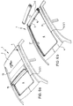
- FIGS. 6a and 6b Various possible opening positions of the folding roof 1 can be seen from FIGS. 6a and 6b. These opening positions can be implemented individually or in combination with one another, although of course these representations do not reflect all possible ways of opening.
- 6a for example, the front area of the roof opening 6 is exposed in that the sliding connection device 3 is partially open in this front area.
- the field formed between a cross bracing 19 and the front edge of the cover part 2 is folded back onto the part of the cover part 2 still attached and can be fixed and held in this position with corresponding additional devices.
- tab-eye connections or interlocking devices come into consideration.
- Velcro fasteners can be used for this.
- FIG. 6a in the area of the rear transverse edge of the roof opening 6 the flexible cover part 2 is partially opened, so that the folding roof 1 in FIG. 6a also has a ventilation position and the air from the vehicle interior due to suction in the area of the rear edge 31 of the folding roof 1 can emerge.
- Fig. 6b the folding roof 1 is shown in such a state in which the roof opening 6 is almost completely released, but is still held in the area of the rear transverse edge on the fixed roof part 4 and rolled up there.
- the cover part 2 can even be removed altogether, and it can be stowed in the vehicle, so that the vehicle occupants have a convertible-like feeling through the completely exposed roof opening 6 is conveyed.
- the folding roof 1 enables the largest possible area of the roof opening 6 to be exposed, but that certain intermediate positions are also possible with the cover part 2, so that the cover part 2 of the folding roof 1 can partially release the roof opening 6 in a variety of ways. If, for example, the removed cover part 2 is to be attached again to close the roof opening 6, it is placed over the roof opening 6 such that the edge stiffeners 16, 16 'and the tensioning cable 21 of the flexible cover part 2, as shown in FIGS.
- the assembly of the folding roof 1 will be briefly explained below. Installation on the vehicle assembly line serves as an example.
- the vehicle roof reaches the assembly station for the folding roof 1 in such a way that the upstanding boundary edge 7 of the roof opening 6 is already preformed.
- the profile part 5, 5 ' is then plugged onto this upstanding boundary edge 7 in the manner shown in FIG. 2.
- the flexible cover part 2 needs to be placed under positioning with the aid of the profile part 5, 5 ', and the sections 3', 3 '' of the sliding connection device 3 can then be closed with a smooth sliding movement of the slide or slides 15, and then the folding roof 1 is reliably and tightly connected to the fixed roof part 4 of the vehicle and with the tensioning device 34 a predetermined convertible top tension is applied.
- the flexible cover part 2 with the inserted cross stiffeners 19, the edge stiffeners 16, 16 'and the circumferential tensioning cable as a further stiffening part 21 is designed as a prefabricated supplier part.
- the folding roof 1 can be installed quickly and easily in the roof opening 6 of the vehicle. An inexpensive installation is thus achieved.
- the design can also be made, for example, in such a way that the cover part 2, without using a sliding connection device 3, for example on the rear Cross edge of the roof opening 6 can be fastened.
- interlocking devices can optionally be provided, which can be detached from each other after unlocking and unlocking so that the cover part 2 can be removed from the vehicle roof as a whole.
- the cover part 2 can also comprise, for example, only two folding fields in deviation from the embodiment shown.
- the design of the folding roof 1 can be made such that the cross stiffeners 19 have a curved profile in cross section.
Abstract
Description
Die Erfindung bezieht sich auf ein Faltdach für Fahrzeuge mit einem flexiblen, faltbaren Abdeckteil, welches über eine teilbare Gleitverbindungseinrichtung, wie einen teilbaren Reißverschluß o.dgl., mit einem festen Dachteil verbindbar ist, welches eine Dachöffnung aufweist.The invention relates to a folding roof for vehicles with a flexible, foldable cover part, which can be connected via a divisible sliding connection device, such as a divisible zipper or the like, to a fixed roof part which has a roof opening.
Aus GB-PS 2076751 A sind ein Verfahren und eine Vorrichtung zum Festlegen eines öffenbaren Dachs oder Dachteils eines Fahrzeugs bekannt. Hierbei wird ein öffenbares, vorzugsweise aus einem flexiblen Material bestehendes Dachteil an einem angrenzenden Teil eines Fahrzeugs dadurch fest angebracht, daß eine Hälfte einer teilbaren Gleitverbindungseinrichtung an dem Dach oder dem Dachteil und die andere Hälfte hiervon an dem angrenzenden festen Karosserieteil angebracht ist. Durch das Schließen oder Öffnen der teilbaren Gleitverbindungseinrichtung wird dann das flexible Dachteil an dem festen Karosserieteil, wie einem festen Dachteil, angebracht oder läßt sich von diesem abnehmen. Als teilbare Gleitverbindungseinrichtungen sind dort ein Reißverschluß mit zwei Bändern von ineinandergreifenden Zähnen und einem Schieber oder Kunststoffstrangteile angegeben, die komplementär zueinander ausgebildet sind und wechselseitig in Formschluß miteinander verriegelbar sind. Hierbei werden die den jeweiligen Teilen zugeordneten Tragbänder der teilbaren Gleitverbindungseinrichtung einerseits am festen Dachteil und andererseits an einer starren und festen Einlage des flexiblen Abdeckteils mit Hilfe von Nietverbindungen o.dgl. angebracht. Gesondert hierzu ist eine Dichtung vorgesehen, die eine Abdichtung des Spalts zwischen dem mit dem flexiblen Material des Abdeckteils überzogenen starren Einlageteil und dem festen Dachteil bewirkt, wenn das flexible Abdeckteil mittels der teilbaren Gleitverbindungseinrichtung an dem karosseriefesten Teil angebracht ist. Da bei diesem Sonnendach das flexible Dachteil im Bereich seiner Außenränder einen starren Versteifungsrahmen hat, wird hierdurch die Flexibilität des Abdeckteils zum Freilegen der Dachöffnung eingeschränkt. Ferner sind zur Verwirklichung dieses Dachaufbaus mehrere zusätzliche Arbeitsschritte wie Anbringen der Dichtung und der jeweiligen Tragbänder der teilbaren Gleitverbindungseinrichtung an den jeweils zugeordneten Teilen, erforderlich, so daß hierdurch bedingt die Herstellung und Montage zeitaufwendig und kompliziert werden.From GB-PS 2076751 A a method and a device for fixing an openable roof or roof part of a vehicle are known. In this case, an openable roof part, preferably made of a flexible material, is firmly attached to an adjacent part of a vehicle in that half of a separable sliding connection device is attached to the roof or the roof part and the other half thereof to the adjacent fixed body part. By closing or opening the divisible sliding connection device, the flexible roof part is then attached to the fixed body part, such as a fixed roof part, or can be removed therefrom. A zipper with two bands of interlocking teeth and a slider or plastic strand parts are specified as divisible sliding connection devices, which are complementary to one another and can be mutually interlocked in positive engagement. In this case, the supporting bands of the divisible sliding connection device assigned to the respective parts are on the one hand on the fixed roof part and on the other hand on a rigid and fixed insert of the flexible cover part with the aid of rivet connections or the like. appropriate. Separately, a seal is provided which effects a seal of the gap between the rigid insert part covered with the flexible material of the cover part and the fixed roof part when the flexible cover part is attached to the part fixed to the body by means of the divisible sliding connection device. Since in this sunroof the flexible roof part has a rigid stiffening frame in the area of its outer edges, this limits the flexibility of the cover part to expose the roof opening. Furthermore, several additional work steps such as attaching the seal and the respective support straps of the divisible sliding connection device to the respectively assigned parts are required for realizing this roof structure, so that the manufacture and assembly are time-consuming and complicated.
Aus DE-A 38 41 035 sind eine Anordnung zur Fensterbefestigung an einem flexiblen Verdeck und ein Verfahren zum Herstellen einer lösbaren Fensterverbindung bekannt. Zur Herstellung einer derartigen lösbaren Fensterverbindung wird das Tragband eines Reißverschlusses an der Innenseite einer Verdeckbespannung und das andere Tragband des Reißverschlusses an der Innenseite der Fensterscheibe befestigt. Sowohl die fertige Bespannung als auch die Fensterscheibe sind hierbei flexibel, so daß mit Hilfe des Reißverschlusses zwei in sich flexible Teile beispielsweise bei einem flexiblen Klappverdeck verbunden werden. Diese Reißverschlußverbindung ist zwischen der Fensterscheibe und der Verdeckbespannung vorgesehen, um die Fensterscheibe leicht und schnell auswechseln zu können, falls sie verkratzt oder anderweitig beschädigt ist. Ein teilweises Öffnen oder Schließen des Fensters ist dort weder angesprochen noch beabsichtigt.DE-A 38 41 035 discloses an arrangement for fastening windows to a flexible roof and a method for producing a detachable window connection. For the production Such a detachable window connection, the carrying strap of a zipper is attached to the inside of a roof covering and the other carrying strap of the zipper is attached to the inside of the window pane. Both the finished covering and the window pane are flexible, so that with the help of the zipper two flexible parts can be connected, for example with a flexible folding top. This zipper connection is provided between the window pane and the roof covering in order to be able to replace the window pane easily and quickly in the event that it is scratched or otherwise damaged. Partial opening or closing of the window is neither addressed nor intended there.
Aus DE GM 82 05 999 ist ein Verdeckbezug für ein Klappverdeck eines Fahrzeugs, insbesondere eines Personenwagens, bekannt, der sich aus zwei hintereinanderliegenden, über einen Reißverschluß lösbar miteinander verbundenen Verdeckabschnitten zusammensetzt, die beide Außenhautabschnitte des Fahrzeuges bilden. Hierbei sollen die bei der Herstellung des Verdeckbezuges auftretenden Fertigungstoleranzen zuverlässig ausgeglichen werden, und der Verdeckbezug soll bei geschlossenem Klappverdeck immer funktionsgerecht gespannt sein. Hierzu ist eine Innenlage aus einem federnd elastischen Werkstoff hergestellt und unter Vorspannung zwischen dem ersten Verdeckabschnitt und dem zweiten Verdeckabschnitt angeordnet. Auch hierbei werden also zwei flexible Verdeckabschnitte mittels einer Reißverschlußverbindung miteinander verbunden. Zum Auf- und Zuklappen des Klappverdecks ist ein Gelenksystem vorgesehen. Ein solcher Dachaufbau ist insbesondere für sogenannte Cabrio-Fahrzeuge bestimmt. Auf die Verbindung der flexiblen Abdeckabschnitte mit karosseriefesten Teilen wird hierbei nicht eingegangen.From DE GM 82 05 999 a convertible top cover for a convertible top of a vehicle, in particular a passenger car, is known which is composed of two successive convertible top sections which are connected to one another by a zipper and form both outer skin sections of the vehicle. Here, the manufacturing tolerances that occur during the manufacture of the convertible top cover should be reliably compensated for, and the convertible top cover should always be tensioned in a functional manner when the convertible top is closed. For this purpose, an inner layer is made of a resiliently elastic material and is placed under prestress between the first convertible top section and the second convertible top section. Here, too, two flexible convertible top sections are connected to one another by means of a zipper connection. An articulated system is provided for opening and closing the folding top. Such a roof structure is particularly intended for so-called convertible vehicles. The connection of the flexible cover sections with parts fixed to the body is not discussed here.
Demgegenüber zielt die Erfindung darauf ab, ein Faltdach für ein Fahrzeug mit einem flexiblen, faltbaren Abdeckteil der gattungsgemäßen Art bereitzustellen, das sich zum wenigstens teilweisen Freigeben der Dachöffnung universell öffnen und schließen läßt, und das sich hinsichtlich der Herstellung und der Montage in wesentlich vereinfachter Form darstellen läßt. Auch soll eine zuverlässige Abdichtung zwischen dem flexiblen Abdeckteil und dem festen Dachteil gegeben sein.In contrast, the invention aims to provide a folding roof for a vehicle with a flexible, foldable cover part of the generic type, which can be opened and closed universally for at least partially releasing the roof opening, and which can be manufactured and assembled in a substantially simplified form represents. There should also be a reliable seal between the flexible cover part and the fixed roof part.
Nach der Erfindung zeichnet sich hierzu ein Faltdach für Fahrzeuge mit einem flexiblen, faltbaren Abdeckteil, welches über eine teilbare Gleitverbindungseinrichtung, wie einen teilbaren Reißverschluß o.dgl., mit einem festen Dachteil verbindbar ist, welches eine Dachöffnung aufweist, dadurch aus, daß an der Begrenzungskante der Dachöffnung ein Profilteil derart vorgesehen ist, daß es einerseits im Zusammenwirken mit dem Abdeckteil eine Außenabdichtung bildet, und andererseits am Profilteil fahrzeuginnenseitig eine Hälfte der teilbaren Gleitverbindungseinrichtung vorgesehen ist.According to the invention, a folding roof for vehicles with a flexible, foldable cover part, which can be connected via a divisible sliding connection device, such as a divisible zipper or the like, to a fixed roof part, which has a roof opening, characterized in that at the Boundary edge of the roof opening, a profile part is provided such that it forms an external seal in cooperation with the cover part, and on the other hand half of the divisible sliding connection device is provided on the profile part inside the vehicle.
Bei dem erfindungsgemäßen Faltdach wird also ein Profilteil an der die Dachöffnung umgebenden Begrenzungskante vorgesehen, welches in funktioneller Hinsicht eine Doppelfunktion erfüllt. Zum einen bildet das Profilteil im Zusammenwirken mit dem flexiblen Abdeckteil eine Außenabdichtung, so daß zusätzliche Dichtungsteile oder Dichtungselemente entfallen können, und zudem dient das Profilteil zugleich als Träger für eine Hälfte der teilbaren Gleitverbindungseinrichtung, so daß durch dieses synergistische Zusammenwirken der Eigenschaften des Profilteils und unter Ausnutzung des Eigenelastizitätsverhaltens des Profilteils sowohl eine zuverlässige Abdichtung als auch eine leichtgängige teilbare Gleitverbindungseinrichtung zum flexiblen Abdeckteil erhalten werden. Da diese Funktionen in einem Teil, dem Profilteil, vereinigt sind, vereinfacht sich die Herstellung eines solchen Faltdaches und zugleich die Montage desselben. Insbesondere ist eine solche Auslegung eines Faltdachs auch für den Einbau im Fahrzeugmontageband geeignet. Somit behält das flexible, faltbare Abdeckteil weitgehend seine Flexibilität bei und es läßt sich das Faltdach auf nahezu universelle Weise entsprechend den jeweiligen Wünschen öffnen und schließen und es ist sogar möglich, das Faltdach insgesamt vom Fahrzeugdach abzunehmen, und beispielsweise im Gepäckraum des Fahrzeugs zu verstauen. Somit läßt sich mit Hilfe des erfindungsgemäßen Faltdachs eine möglichst große Dachöffnung auf kostengünstige und montagefreundliche Weise im Bedarfsfall bereitstellen.In the folding roof according to the invention, a profile part is therefore provided on the boundary edge surrounding the roof opening, which functionally fulfills a double function. On the one hand, the profile part forms an outer seal in cooperation with the flexible cover part, so that additional sealing parts or sealing elements can be omitted, and in addition, the profile part also serves as a carrier for half of the divisible sliding connection device, so that the properties of the profile part and synergistically interact through this Utilization of the inherent elastic behavior of the profile part provides both a reliable seal and an easy-to-use, separable sliding connection device for the flexible cover part will. Since these functions are combined in one part, the profile part, the manufacture of such a folding roof and at the same time the assembly of the same are simplified. In particular, such a design of a folding roof is also suitable for installation in the vehicle assembly line. Thus, the flexible, foldable cover part largely retains its flexibility, and the folding roof can be opened and closed in an almost universal manner according to the respective requirements, and it is even possible to remove the folding roof as a whole from the vehicle roof and, for example, to stow it in the luggage compartment of the vehicle. Thus, with the help of the folding roof according to the invention, the largest possible roof opening can be provided in an inexpensive and easy-to-install manner if necessary.
Vorzugsweise hat das Profilteil einen spitzwinklig zur Dachöffnungsbegrenzungskante angeordneten, fahrzeuginnenseitigen Schenkel, der die eine Hälfte der teilbaren Gleitverbindungseinrichtung trägt. Diese Hälfte der Gleitverbindungseinrichtung kann an diesem Schenkel des Profilteils beispielsweise mittels Kleben o.dgl. befestigt werden, oder die Hälfte kann auch direkt an diesem Schenkel angeformt sein. Somit braucht zur Verwirklichung des erfindungsgemäßen Faltdachs lediglich an der Begrenzungskante der Dachöffnung das Profilteil vorgesehen zu werden, an dem bereits eine Hälfte der teilbaren Gleitverbindungseinrichtung vorhanden ist, so daß man keine zusätzlichen Befestigungsmittel für die teilbare Gleitverbindungseinrichtung benötigt.The profile part preferably has an arm inside the vehicle which is arranged at an acute angle to the edge of the roof opening and which carries one half of the separable sliding connection device. This half of the sliding connection device can or the like on this leg of the profile part, for example by gluing. can be attached, or half can also be molded directly onto this leg. Thus, in order to realize the folding roof according to the invention, the profile part, on which half of the separable sliding connection device is already present, only needs to be provided on the boundary edge of the roof opening, so that no additional fastening means for the separable sliding connection device are required.
Vorzugsweise ist an der Vorderkante und/oder Hinterkante des Abdeckteils im Abstand vom Außenrand wenigstens eine Randaussteifung vorgesehen, welche das flexible Abdeckteil versteift und zugleich zur Positionierung des Abdeckteils am Profilteil dient.At least one edge stiffener is preferably provided on the front edge and / or rear edge of the cover part at a distance from the outer edge, which stiffens the flexible cover part and at the same time serves to position the cover part on the profile part.
Da vorzugsweise die Zweite Hälfte der teilbaren Gleitverbindungseinrichtung am Abdeckteil an einer solchen Stelle angebracht ist, die von dieser Berührung der Randaussteifung mit dem Profilteil in Richtung nach innen liegt, kann das flexible Abdeckteil Zuverlässig so auf dem Profilteil positioniert werden, daß die beiden zu verbindenden Hälften der teilbaren Gleitverbindungseinrichtung so zueinander ausgerichtet sind, daß der oder die zugeordneten Schieber leichtgängig zum Trennen oder Verbinden verschoben werden können, ohne daß es hierzu umständlicher Einfädelungsarbeiten bedarf.Since preferably the second half of the divisible sliding connection device is attached to the cover part at such a point which lies inward from this contact of the edge stiffener with the profile part, the flexible cover part can be reliably positioned on the profile part in such a way that the two halves to be connected the divisible sliding connection device are aligned with one another in such a way that the associated slide or slides can be moved easily for disconnection or connection without the need for laborious threading work.
Um eine möglichst zuverlässige Abdichtung zwischen dem flexiblen Abdeckteil und dem festen Dachteil zu erreichen, übergreift der Außenrandbereich des Abdeckteils die Außenseite des Profilteils, so daß man einen möglichst großen Dichtbereich erhält. Zweckmäßigerweise weist der Außenrandbereich des Abdeckteils einen Saum auf, in dem ein weiteres Versteifungsteil, wie ein Spannseil oder dergleichen, angeordnet ist, so daß man eine sichere und zuverlässige Anlage des flexiblen Abdeckteils an dem Profilteil zwischen den Bandversteifungen und dem Spannseil im Saum erhält. Zusätzlich kann das Abdeckteil wenigstens eine Querversteifung umfassen, um beispielsweise einen Bruch des Faltdaches durch Schneelasten o.dgl. zu vermeiden. Auch wird hierdurch die passive Fahrzeugsicherheit verbessert. Vorzugsweise sind in Längsrichtung des Abdeckteils wenigstens zwei Querversteifungen vorgesehen, die in regelmäßigen Abständen voneinander in Längsrichtung vorgesehen sind. Hierdurch wird dem flexiblen Abdeckteil zwar eine gewisse Eigensteifigkeit verliehen, die aber hinsichtlich der Brauchbarkeit die Faltdachfunktion im wesentlichen nicht beeinträchtigen.In order to achieve the most reliable possible seal between the flexible cover part and the fixed roof part, the outer edge area of the cover part extends over the outside of the profile part, so that the largest possible sealing area is obtained. The outer edge region of the cover part expediently has a hem, in which a further stiffening part, such as a tensioning cable or the like, is arranged, so that one obtains a safe and reliable contact of the flexible cover part with the profile part between the band stiffeners and the tensioning cable in the hem. In addition, the cover part can comprise at least one cross-bracing, for example to prevent the folding roof from breaking due to snow loads or the like. to avoid. This also improves passive vehicle safety. Preferably, at least two transverse stiffeners are provided in the longitudinal direction of the cover part, which are provided at regular intervals from one another in the longitudinal direction. As a result, the flexible cover part is given a certain inherent stiffness, but does not essentially impair the folding roof function in terms of usability.
Die Randaussteifung wird zweckmäßigerweise von Rohrteilen gebildet. Gleiches gilt auch für die Querversteifungen.The edge stiffening is expediently formed by tubular parts. The same applies to the cross stiffeners.
Der Aussteifungsrahmen wird zweckmäßigerweise von Rohrteilen gebildet. Gleiches gilt auch für die Querversteifungen. Die weiteren in den Saum eingelegten Aussteifungsteile werden vorzugsweise von einem Stabmaterial gebildet, das kleinere Abmessungen hat.The stiffening frame is expediently formed by tubular parts. The same applies to the cross stiffeners. The other stiffening parts inserted into the hem are preferably formed from a rod material that has smaller dimensions.
Im Hinblick auf die universelle Einsetzbarkeit des Faltdaches ist die teilbare Gleitverbindungseinrichtung wenigstens so vorgesehen, daß es sich über die beiden Längsseiten und wenigstens eine Querseite des Abdeckteils erstreckt. Vorzugsweise ist sie wenigstens in zwei Teilstücke unterteilt, wobei als Symmetrieachse die in Fahrzeuglängsrichtung verlaufende Mittelachse der Dachöffnung genommen werden kann. Insbesondere ist die Gleitverbindungseinrichtung derart beschaffen, daß das Abdeckteil von vorne und/oder von hinten öffen- und schließbar ist, so daß man die jeweils gewünschte Belüftungsmöglichkeit wählen kann. Um den Öffnungs- und Schließvorgang möglichst einfach zu gestalten, umfaßt die Gleitverbindungseinrichtung wenigstens zwei Schieber, die in Gegenrichtungen zum Öffnen und Schließen der Gleitverbindungseinrichtung bewegbar sind. Somit kann man beim Öffnen und Schließen die zurückzulegenden Bewegungsweglängen pro Teil der Gleitverbindungseinrichtung verkleinern, so daß das Faltdach hierdurch äußerst bedienungsfreundlich wird.With regard to the universal applicability of the folding roof, the divisible sliding connection device is at least provided such that it extends over the two long sides and at least one transverse side of the cover part. It is preferably divided into at least two sections, the central axis of the roof opening running in the longitudinal direction of the vehicle being taken as the axis of symmetry. In particular, the sliding connection device is designed such that the cover part can be opened and closed from the front and / or from the rear, so that the desired ventilation option can be selected in each case. In order to make the opening and closing process as simple as possible, the sliding connection device comprises at least two slides which can be moved in opposite directions for opening and closing the sliding connection device. Thus, when opening and closing the movement path lengths to be covered per part of the sliding connection device can be reduced, so that the folding roof is thereby extremely user-friendly.
Vorzugsweise ist das Profilteil als Umlaufprofilteil und einteilig ausgelegt, um den Montageaufwand so weit wie möglich zu reduzieren, wobei das Profilteil so beschaffen ist, daß es sich beispielsweise auf die Begrenzungskante der Dachöffnung aufstecken läßt, so daß diese Begrenzungskante zugleich als Aufnahme und Halter für das Profilteil dient.Preferably, the profile part is designed as a circumferential profile part and in one piece in order to reduce the assembly effort as much as possible, the profile part being designed such that it can be plugged onto the boundary edge of the roof opening, for example, so that this boundary edge also serves as a receptacle and holder for the Profile part serves.
Vorzugsweise ist dem Abdeckteil eine Spanneinrichtung zugeordnet, die von einem dachfest abgestützen Federbügel beispielsweise gebildet werden kann. Diese Spanneinrichtung erzeugt in der Schließstellung des Abdeckteils eine vorbestimmte Spannung, so daß das Abdeckteil und das Material desselben in der Schließlage zuverlässig gespannt sind und ein ansprechendes Äußeres vermitteln. Die übereinandergelegten Abschnitte des Abdeckteils bei wenigstens teilweise freigelegter Dachöffnung können so beschaffen und ausgelegt sein, daß sie in den jeweiligen Klappstellungen lösbar zusammengehalten sind. Hierzu kommen Klettverschlüsse oder Ösen-Schlaufenverbindungen oder Laschenverbindungen oder Schnappverbindungen in Betracht.A tensioning device is preferably assigned to the cover part, which can be formed, for example, by a spring bracket supported on the roof. This clamping device generates a predetermined tension in the closed position of the cover part, so that the cover part and the material of the same are reliably clamped in the closed position and convey an appealing exterior. The superimposed sections of the cover part with at least partially exposed roof opening can be designed and designed so that they are detachably held together in the respective folding positions. Velcro fasteners or eyelet-loop connections or tab connections or snap connections come into consideration here.
Die Erfindung wird nachstehend anhand von bevorzugten Ausführungsformen unter Bezugnahme auf die beigeführte Zeichnung näher erläutert. Darin Zeigt:
- Fig. 1
- mit den Fig. 1a und 1b eine perspektivische Draufsicht einer ersten bevorzugten Ausführungsform eines Faltdaches nach der Erfindung mit Schnittdarstellungen,
- Fig. 2
- eine Schnittansicht im Bereich der Schnittlinie II-II in Fig. 1 zur Verdeutlichung einer Ausführungsvariante der Anbindung einer Gleitverbindungseinrichtung,
- Fig. 3
- eine den Bereich in Fig. 2 entsprechende Schnittansicht zur Verdeutlichung einer abgewandelten Ausführungsform des Abdeckteils im Zusammenwirken mit dem Profilteil,
- Fig. 4
- eine Schnittansicht im Bereich der Schnittlinie IV-IV in Fig. 1 zur Verdeutlichung der Abdeckteils nach den Fig. 2 und 3 im Bereich der Längsseiten des Faltdachs,
- Fig. 5
- eine schematische Ansicht einer Auslegungsform einer Einrichtung, welche beim Schließen des Faltdachs eine Spannung auf das Abdeckteil aufbringt,
- Fig. 6a und 6b
- schematische Ansichten der wesentlichen Öffnungsmöglichkeiten für die Fahrzeugdachöffnung mittels des erfindungsgemäßen Faltdaches.
- Fig. 1
- 1a and 1b show a perspective top view of a first preferred embodiment of a folding roof according to the invention with sectional views,
- Fig. 2
- 2 shows a sectional view in the area of section line II-II in FIG. 1 to illustrate an embodiment variant of the connection of a sliding connection device,
- Fig. 3
- 2 shows a sectional view corresponding to the area in FIG. 2 to illustrate a modified embodiment of the cover part in cooperation with the profile part,
- Fig. 4
- 2 shows a sectional view in the area of the section line IV-IV in FIG. 1 to illustrate the cover part according to FIGS. 2 and 3 in the area of the long sides of the folding roof,
- Fig. 5
- 2 shows a schematic view of a design form of a device which applies a tension to the cover part when the folding roof is closed,
- 6a and 6b
- schematic views of the essential opening options for the vehicle roof opening by means of the folding roof according to the invention.
In den Figuren der Zeichnung sind gleiche oder ähnliche Teile mit denselben Bezugszeichen versehen.In the figures of the drawing, identical or similar parts are provided with the same reference symbols.
Zuerst werden unter Bezugnahme auf die Fig. 1 und 2 die wesentlichen Einzelheiten der dargestellten bevorzugten Ausführungsform eines insgesamt mit 1 bezeichneten Faltdaches erläutert. Das Faltdach 1 umfaßt ein flexibles, faltbares Abdeckteil 2, welches über eine teilbare Gleitverbindungseinrichtung 3, wie einen Reißverschluß, mit einem festen Dachteil 4 unter Zwischenschaltung eines Profilteils 5 verbunden ist. Wie insbesondere aus Fig. 2 zu ersehen ist, wird eine Dachöffnung 6, die im festen Dachteil 4 vorgesehen ist, von einer beispielsweise etwa senkrecht hochstehenden Begrenzungskante 7 umgeben. Auf diese über den Umriß der Dachöffnung 6 umlaufende Begrenzungskante 7 ist das vorzugsweise einteilig ausgelegte Profilteil 5 aufgesteckt, das zweckmäßigerweise aus einem geeigneten Kunststoffmaterial besteht. Dieses Profilteil 5 umschließt zur Erhöhung seiner Eigenelastizität in einem Teilbereich, nämlich dem Dichtungsbereich 8, einen Hohlraum. Dieser Dichtungsbereich 8 liegt von der Dachöffnung aus gesehen in Richtung nach außen und das Profilteil 5 ist noch auf einem Teil der festen Dachkonstruktion abgestützt. Fahrzeuginnenseitig, d.h. in Richtung zur Dachöffnung 6 weisend, hat das Profilteil 5 einen Schenkel 9, der vorzugsweise spitzwinklig zu dem etwa senkrecht und parallel zur Begrenzungskante 7 verlaufenden Stegteil 10 sich erstreckt. Dieser Schenkel 9 dient als Halter und Träger für eine Hälfte 11 der teilbaren Gleitverbindungseinrichtung 3. Die zweite Hälfte 12 der teilbaren Gleitverbindungseinrichtung 3 ist über ein Verbindungsteil 13 mit dem flexiblen Abdeckteil 2 verbunden. Mit Hilfe eines Schiebers 15 lassen sich die beiden Hälften 11, 12 der Gleitverbindungseinrichtung 3 trennen oder zusammenfügen. Bei der bevorzugten Ausführungsform dient als ein Beispiel für eine derartige teilbare Gleitverbindungseinrichtung 3 ein Reißverschluß mit entsprechenden Zahnketten. Als weiteres Beispiel für eine derartige, teilbare Gleitverbindungseinrichtung 3 kommt beispielsweise eine solche in Betracht, die ein Paar komplementärer, in wechselseitigem Formschluß miteinander verriegelbarer Profilstränge umfaßt. Auch können beim erfindungsgemäßen Faltdach 1 Kombinationen beider teilbarer Gleitverbindungseinrichtungen 3 in Betracht kommen.First, with reference to FIGS. 1 and 2, the essential details of the illustrated preferred embodiment of a folding roof designated overall by 1 are explained. The folding roof 1 comprises a flexible,
Das flexible, faltbare Abdeckteil 2 weist insbesondere nach Fig. 1 eine Randaussteifung 16 an einer Vorderkante 30 und/oder einer Hinterkante 31 auf, die in einem Abstand vom äußeren Rand 17 des Abdeckteils 2 angeordnet ist. Diese Randaussteifung 16 umfaßt vorzugsweise ein Rohrteil 18. Au äußeren Rand 17 des Abdeckteils 2 ist ein Saum 20 vorgesehen, der von einer Doppellage des flexiblen Materials des Abdeckteils 2 gebildet wird. In diesem Saum 20 ist ein weiteres Versteifungsteil 21 eingelegt, das vorzugsweise von einem umlaufenden Spannseil gebildet wird. Bei Verwendung eines Stahlseils als Spannseil ist zwischen den Enden desselben vorzugsweise eine Feder als Zwischenverbindung vorgesehen.The flexible,
Bei der in Fig. 2 gezeigten Schließstellung der teilbaren Gleitverbindungseinrichtung 3 liegt die Randaussteifung 16 teilweise an dem Profilteil 5 innenseitig an, während das weitere, stabförmige Versteifungsteil 21, wie das Spannseil, im Saum 20 an dem Profilteil 5 außenseitig anliegt. Somit wird das flexible Abdeckteil 2 mit Hilfe der Randaussteifung 16 und dem Spannseil 21 am Profilteil 5 in einer vorbestimmten Lage positioniert, so daß man einen definierten Dichtungsbereich 8 von Abdeckteil 2 und Profilteil 5 zwischen der Randaussteifung 16 und dem Spannseil 21 erhält, wobei im geschlossenen Zustand der teilbaren Gleitverbindungseinrichtung 3 der entsprechende Bereich des flexiblen Abdeckteils 2 in Anlage gegen das Profilteil 5 angedrückt und gespannt wird.In the closed position of the divisible sliding
Selbst wenn beispielsweise die teilbare Gleitverbindungseinrichtung offen ist, ist das flexible Abdeckteil 2 mit Hilfe der Randaussteifung 16 und dem Spannseil 21 an dem Profilteil 5 so positioniert, daß die beiden Hälften 11, 12 der Gleitverbindungseinrichtung 3 in vorbestimmter Weise so zueinander ausgerichtet sind, daß man bei einer leichtgängigen Gleitverschiebung des Schiebers 15 diese Gleitverbindungseinrichtung 3 einfach schließen kann. Zweckmäßigerweise sind der Schenkel 9 und das Verbindungsteil 13, welche die beiden Hälften 11, 12 der Gleitverbindungseinrichtung 3 tragen, aus einem Material mit ähnlichen Elastizitätseigenschaften hergestellt, so daß eine möglichst weitgehende Entlastung beim Schließen der Gleitverbindungseinrichtung 3 erreicht wird.Even if, for example, the divisible sliding connection device is open, the
In Fig. 3 ist eine Ausführungsvariante zu der Ausführungsform nach Fig. 2 gezeigt. In Abweichung zu dem Beispiel nach Fig.2 wird hierbei die Randaussteifung 16 von einer ebenen, streifenförmigen Versteifungseinlage 22 gebildet. Ansonsten stimmen die Einzelheiten weitgehend mit jenen überein, die im Zusammenhang mit Fig. 2 erläutert wurden, und die hiermit übereinstimmenden Teile sind mit denselben Bezugszeichen versehen.FIG. 3 shows an embodiment variant of the embodiment according to FIG. 2. In a departure from the example according to FIG. 2, the edge stiffening 16 is formed by a flat, strip-shaped
Fig. 4 verdeutlicht in einer Schnittansicht im Bereich der Längskante des Abdeckteils 2 das Zusammenwirken von Abdeckteil 2 und Profilteil 5 in der Schließstellung des Faltdaches 1. Wie hieraus zu ersehen ist, ist das Profilteil 5 umlaufend auf die Begrenzungskante 7 der Dachöffnung aufgesteckt. Im Bereich der Längskante des Abdeckteils 2 ist aber nur im Bereich des Saumes 20 das Spannseil 21 als Versteifung vorgesehen, während weitere versteifende Einlagen fehlen.Fig. 4 illustrates in a sectional view in the region of the longitudinal edge of the
In Fig. 1a ist eine Ausführungsvariante für eine Anbindung der Gleitverbindungseinrichtung 3 an das feste Dachteil 4 verdeutlicht. Wie bei den voranstehend beschriebenen Ausführungsformen ist auf die hochstehende Begrenzungskante 7 der Dachöffnung 6 ein Profilteil 5' aufgesteckt und übergreift ein Tragteil 32, das beispielsweise mittels Anpunkten fest an der Begrenzungskante 7 der Dachöffnung 6 angebracht ist. Dieses Tragteil 32 hat zur Dachinnenseite weisend eine rinneförmige Ausnehmung 33, in der die erste Hälfte 11 der Gleitverbindungseinrichtung 3 vorzugsweise formschlüssig aufgenommen ist. Die zweite Hälfte 12 der Gleitverbindungseinrichtung 3 ist an einem Ende 34 des Materials des Abdeckteils 2 befestigt, das im Bereich des äußeren Randes 17 unter Bildung eines Saumes 20 auf sich selbst zurückgefaltet ist.FIG. 1 a shows an embodiment variant for connecting the sliding
Ferner ist bei dieser Auslegungsform an der Vorderkante 30 oder auch an der Hinterkante 31 des Abdeckteils 2 ein vorzugsweise L-förmig gebogenes Randaussteifungsteil 16' in den dort gebildeten Saum 20 eingelegt.Furthermore, in this embodiment, a preferably L-shaped
Aus Fig. 1b ist eine Knotenstelle zwischen einer Querversteifung 19 und dem Profilteil 5' zu ersehen. Die Querversteifung 19 wird von einem Rohrteil gebildet, mit dem in Art einer Steckverbindung ein Einlageteil 35 verbunden ist, welches L-förmig ausgelegt ist und das Profilteil 5 außenseitig wenigstens teilweise übergreift. Gegebenenfalls können die Querversteifungen 19 massiv ausgebildet werden. Diese Querversteifungen 19 sind in das flexible Material des Abdeckteils 2 eingebettet. Gleiche oder ähnliche Querversteifungen 19 können auch bei den anhand den Fig. 2 bis 4 erläuterten Ausführungsformen des Faltdachs 1 vorgesehen sein. Bei dem in Fig. 1 gezeigten Beispiel sind zwei derartige Querversteifungen 19 in Längsrichtung des Abdeckteils im Abstand voneinander vorgesehen.1b shows a node between a cross bracing 19 and the profile part 5 '. The
In Fig. 5 ist schematisch eine Spanneinrichtung 36 verdeutliche, welche beim Schließen des Abdeckteils 2 eine vorbestimmte Spannung auf dasselbe aufbringt, so daß im geschlossenen Zustand des Abdeckteils 2 dieses in gespannter Lage weitgehend faltenfrei gehalten ist. Im Abstand von der Vorderkante 30 und/oder der Hinterkante 31 ist hierbei ein Federbügel 37 vorgesehen, der sich einerseits an den Längsseiten am festen Dachteil 4 und/oder am Profilteil 5 oder 5' als festen Widerlagerpunkt abstützt und andererseits im Bereich der Vorderkante 30 und/oder der Hinterkante 31 des Abdeckteils 2 mit diesem oder gegebenenfalls einer dort vorgesehenen Randaussteifung 16, 16' verbunden ist. Diese Spanneinrichtung 36 arbeitet derart, daß bei der Schließbewegung unter Abstützung am festen Dachteil 4 und/oder am dachfesten Profilteil 5, 5' unter Ausführung einer Schwenkbewegung beim Nachinnenziehen des Abdeckteils 2 das Material des Abdeckteils mit einer vorbestimmten Spannkraft beaufschlagt. In der Schließstellung des Abdeckteils 2 kann das vordere Ende des Federbügels 37 gegebenenfalls in eine dachfeste Arretierung eingreifen, um zu erreichen, daß der gewünschte Spannungszustand des Abdeckteils 2 bei geschlossenem Faltdach 1 beibehalten wird.5 schematically shows a
Bei dem in Fig. 1 gezeigten Beispiel des Faltdachs 1 ist die Gleitverbindungseinrichtung 3 in wenigstens zwei Teilstücke 3', 3'' unterteilt, wozu wenigstens vier Schieber 15 vorgesehen sind, die jeweils paarweise in Gegenrichtungen zum Öffnen und Schließen der Gleitverbindungseinrichtung 3, 3', 3'' verschiebbar sind. Als Symmetrielinie für die Teilung der Gleitverbindungseinrichtung 3 ist bei diesem Beispiel etwa die in Fahrzeuglängsrichtung durch die Dachöffnung 6 gehende Mittelachse gewählt. In Fig. 1a ist die Gleitverbindungseinrichtung 3 an der vorderen Querkante der Dachöffnung 6 in teilweise geöffnetem Zustand verdeutlicht, und die Bewegungsrichtungen des zugeordneten Schiebers 15 oder der zugeordneten Schieber 15 sind mit Pfeilen verdeutlicht. Aus Fig. 1 läßt sich in analoger Weise der Bereich an der hinteren Querkante der Dachöffnung 6 ersehen.In the example of the folding roof 1 shown in FIG. 1, the sliding
Aus den Fig. 6a und 6b lassen sich verschiedene mögliche Öffnungsstellungen des Faltdachs 1 entnehmen. Diese Öffnungsstellungen können einzeln oder in Kombination miteinander verwirklicht werden, wobei natürlich diese Darstellungen nicht sämtliche mögliche Öffnungsweisen wiedergeben. In Fig. 6a ist beispielsweise der vordere Bereich der Dachöffnung 6 freigelegt, indem die Gleitverbindungseinrichtung 3 in diesem vorderen Bereich teilweise geöffnet ist. Das zwischen einer Querversteifung 19 und dem vorderen Rand des Abdeckteils 2 gebildete Feld ist auf den noch angebrachten Teil des Abdeckteils 2 nach hinten geklappt und kann in dieser Lage mit entsprechenden zusätzlichen Einrichtungen fixiert und festgehalten werden. Hierbei kommen Laschen-Ösenverbindungen oder ineinander verrastbare Einrichtungen in Betracht. In analoger Weise können hierfür Klettverschlüsse verwendet werden.Various possible opening positions of the folding roof 1 can be seen from FIGS. 6a and 6b. These opening positions can be implemented individually or in combination with one another, although of course these representations do not reflect all possible ways of opening. 6a, for example, the front area of the
Ferner ist in Fig. 6a im Bereich der hinteren Querkante der Dachöffnung 6 das flexible Abdeckteil 2 teilweise geöffnet, so daß man zusätzlich bei dem Faltdach 1 in Fig. 6a auch eine Entlüftungsstellung hat und die Luft aus dem Fahrzeuginnenraum durch Sogwirkung im Bereich der Hinterkante 31 des Faltdaches 1 austreten kann.Furthermore, in FIG. 6a in the area of the rear transverse edge of the
Selbstverständlich sind auch Zwischenstellungen des Faltdachs 1 möglich, wobei beispielsweise zwei Felder des dreifeldrigen Abdeckteils 2 aufeinandergeklappt und in dieser Lage fixiert sein können.Of course, intermediate positions of the folding roof 1 are also possible, it being possible, for example, for two fields of the three-
In Fig. 6b ist das Faltdach 1 in einem solchen Zustand gezeigt, bei dem die Dachöffnung 6 nahezu vollständig freigegeben ist, aber noch im Bereich der hinteren Querkante am festen Dachteil 4 gehalten und dort zusammengerollt ist. Wie mit einem Pfeil eingetragen, kann man nach Lösen der Gleitverbindungseinrichtung 3 im Bereich der hinteren Querkante 31 dann das Abdeckteil 2 sogar insgesamt abnehmen, und es kann im Fahrzeug verstaut werden, so daß den Fahrzeuginsassen durch die vollständig freigelegte Dachöffnung 6 ein cabrio-ähnliches Gefühl vermittelt wird.In Fig. 6b the folding roof 1 is shown in such a state in which the
Wie aus den Fig. 6a und 6b zu ersehen ist, ermöglicht das erfindungsgemäße Faltdach 1, daß ein möglichst großer Bereich der Dachöffnung 6 freigelegt werden kann, daß aber auch gewisse Zwischenstellungen bei dem Abdeckteil 2 möglich sind, so daß das Abdeckteil 2 des Faltdaches 1 auf eine Vielzahl von möglichen Weisen die Dachöffnung 6 teilweise freigeben kann. Wenn beispielsweise das abgenommene Abdeckteil 2 wiederum zum Verschließen der Dachöffnung 6 angebracht werden soll, so wird es über die Dachöffnung 6 derart gelegt, daß die Randaussteifungen 16, 16' und das Spannseil 21 des flexiblen Abdeckteils 2, wie dies in Fig. 1 und 2 gezeigt ist, an dem Profilteil 5, 5' so positioniert werden, daß die Hälften 11 und 12 der Gleitverbindungseinrichtung 3 so zueinander liegen, daß sich die Schieber 15 leicht in die Gleitbahn einfädeln lassen, um auf bedienungsfreundliche Weise ein Schließen der Gleitverbindungseinrichtung 3 zu ermöglichen. Mit Hilfe der Spanneinrichtung 36 in Fig. 5 wird dann beim abschließenden Schließen des Abdeckteils 2 eine Verdeckspannung aufgebracht.As can be seen from FIGS. 6a and 6b, the folding roof 1 according to the invention enables the largest possible area of the
Nachstehend soll noch kurz die Montage des Faltdachs 1 erläutert werden. Als Beispiel dient hierbei der Einbau am Fahrzeug-Montageband. Das Fahrzeugdach erreicht die Montagestation für das Faltdach 1 in der Form, daß die hochstehende Begrenzungskante 7 der Dachöffnung 6 bereits vorgeformt ist. Zur Montage wird dann das Profilteil 5, 5' auf die in Fig. 2 gezeigte Weise auf diese hochstehende Begrenzungskante 7 aufgesteckt. Dann braucht nur noch das flexible Abdeckteil 2 unter Positionierung mit Hilfe des Profilteils 5, 5' aufgelegt zu werden, und es können dann die Teilstücke 3', 3'' der Gleitverbindungseinrichtung 3 unter einer leichtgängigen Verschiebebewegung des oder der Schieber 15 geschlossen werden, und dann ist das Faltdach 1 zuverlässig und dicht schließend mit dem festen Dachteil 4 des Fahrzeugs verbunden und mit der Spanneinrichtung 34 wird eine vorbestimmte Verdeckspannung aufgebracht. Das flexible Abdeckteil 2 mit den eingelegten Querversteifungen 19, den Randaussteifungen 16, 16' und dem umlaufenden Spannseil als weiteres Versteifungsteil 21 ist als vorgefertigtes Zulieferteil ausgelegt. Somit läßt sich das Faltdach 1 schnell und einfach in der Dachöffnung 6 des Fahrzeugs montieren. Somit wird ein kostengünstiger Einbau erreicht.The assembly of the folding roof 1 will be briefly explained below. Installation on the vehicle assembly line serves as an example. The vehicle roof reaches the assembly station for the folding roof 1 in such a way that the
Selbstverständlich ist die Erfindung nicht auf die voranstehend beschriebenen Einzelheiten hinsichtlich des Faltdaches 1 beschränkt, sondern es sind zahlreiche Abänderungen und Modifikationen möglich, die der Fachmann im Bedarfsfall treffen wird, ohne den Erfindungsgedanken zu verlassen. Insbesondere kann das Profilteil 5, 5' auch eine von der dargestellten Form abweichende Form haben, und insbesondere in Abhängigkeit von der Größe der Dachöffnung 6 können mehr oder weniger Querversteifungen 19 beim Faltdach 1 gegebenenfalls vorgesehen sein. Auch kann die Auslegung beispielsweise derart getroffen werden, daß das Abdeckteil 2 ohne Verwendung einer Gleitverbindungseinrichtung 3 beispielsweise an der hinteren Querkante der Dachöffnung 6 befestigbar ist. Hierzu können gegebenenfalls ineinandergreifende Einrichtungen vorgesehen sein, die nach einer Entsicherung und Entriegelung so voneinander lösbar sein können, daß sich das Abdeckteil 2 insgesamt vom Fahrzeugdach abnehmen läßt. Auch kann das Abdeckteil 2 beispielsweise nur zwei Klappfelder in Abweichung von der dargestellten Ausführungsform umfassen. Ferner kann in Abhängigkeit von der gegebenenfalls vorhandenen Dachwölbung die Auslegung des Faltdaches 1 so getroffen werden, daß die Querversteifungen 19 im Querschnitt einen gekrümmten Verlauf haben.Of course, the invention is not limited to the details described above with regard to the folding roof 1, but numerous changes and modifications are possible which the person skilled in the art will make if necessary without departing from the inventive concept. In particular, the
- 11
- Faltdach insgesamtOverall folding roof
- 22nd
- AbdeckteilCover part
- 33rd
- GleitverbindungseinrichtungSliding connection device
- 3'3 '
- 3''3 ''
- Teilstücke derselbenSections of the same
- 44th
- festes Dachteilfixed roof part
- 55
- Profilteil insgesamt in Fig. 2-4Overall profile part in Fig. 2-4
- 5'5 '
- Profilteil in Fig. 1, 1a, 1bProfile part in Fig. 1, 1a, 1b
- 66
- DachöffnungRoof opening
- 77
-
Begrenzungskante der Dachöffnung 6Boundary edge of the
roof opening 6 - 88th
- DichtungsbereichSealing area
- 99
- Schenkelleg
- 1010th
- SteckteilPlug-in part
- 1111
-
erste Hälfte der Gleitverbindungseinrichtung am Profilteil 5first half of the sliding connection device on the
profile part 5 - 1212
-
zweite Hälfte der Gleitverbindungseinrichtung am Abdeckteil 2second half of the sliding connection device on the
cover part 2 - 1313
- VerbindungsteilConnecting part
- 1515
- SchieberSlider
- 1616
- RandaussteifungEdge bracing
- 16'16 '
- L-förmiges RandaussteifungsteilL-shaped edge reinforcement
- 1717th
-
äußerer Rand des Abdeckteils 2outer edge of the
cover part 2 - 1818th
- RohrteilPipe part
- 1919th
- Querversteifung(en)Cross bracing (s)
- 2020th
- Saumhem
- 2121
- weiteres Versteifungsteil bzw. Spannseiladditional stiffening part or tension rope
- 2222
- VersteifungseinlageStiffening insert
- 3030th
-
Vorderkante von Abdeckteil 2Front edge of
cover part 2 - 3131
-
Hinterkante von Abdeckteil 2Trailing edge of
cover part 2 - 3232
- TragteilSupport part
- 3333
- rinnenförmige Ausnehmungtrough-shaped recess
- 3434
- Ende des MaterialsEnd of material
- 3535
- EinlageteilInsert part
- 3636
- SpanneinrichtungClamping device
- 3737
- FederbügelSpring clip
Claims (21)
Applications Claiming Priority (2)
| Application Number | Priority Date | Filing Date | Title |
|---|---|---|---|
| DE19904040254 DE4040254C1 (en) | 1990-12-17 | 1990-12-17 | |
| DE4040254 | 1990-12-17 |
Publications (2)
| Publication Number | Publication Date |
|---|---|
| EP0491148A1 true EP0491148A1 (en) | 1992-06-24 |
| EP0491148B1 EP0491148B1 (en) | 1994-09-07 |
Family
ID=6420510
Family Applications (1)
| Application Number | Title | Priority Date | Filing Date |
|---|---|---|---|
| EP19910118608 Expired - Lifetime EP0491148B1 (en) | 1990-12-17 | 1991-10-31 | Flexible top for vehicles |
Country Status (3)
| Country | Link |
|---|---|
| EP (1) | EP0491148B1 (en) |
| JP (1) | JPH04271923A (en) |
| DE (1) | DE4040254C1 (en) |
Families Citing this family (4)
| Publication number | Priority date | Publication date | Assignee | Title |
|---|---|---|---|---|
| DE4319718C1 (en) * | 1993-06-15 | 1994-08-18 | Webasto Karosseriesysteme | Folding roof for vehicles |
| DE19533898C2 (en) * | 1995-09-13 | 2001-07-12 | Anton Bauer | Roof frame |
| DE19616971A1 (en) * | 1996-04-27 | 1997-10-30 | Bayerische Motoren Werke Ag | Motor vehicle with a roof opening |
| DE102021209634A1 (en) | 2021-09-01 | 2023-03-02 | Volkswagen Aktiengesellschaft | Roof system for a motor vehicle, motor vehicle |
Citations (4)
| Publication number | Priority date | Publication date | Assignee | Title |
|---|---|---|---|---|
| GB432141A (en) * | 1934-05-12 | 1935-07-22 | Vanden Plas England 1923 Ltd | Improvements in, or relating to, weather-protective fittings for motor-cars of the open-tourer type |
| GB945571A (en) * | 1961-09-20 | 1964-01-02 | Austin Motor Co Ltd | Improvements relating to motor vehicle roofs |
| US3476437A (en) * | 1965-08-11 | 1969-11-04 | Porsche Kg | Top for motor vehicles,especially for passenger motor vehicles |
| US4611849A (en) * | 1983-03-26 | 1986-09-16 | Dr.Ing. H.C.F. Porsche Ag | Convertible top with interchangeable flexible and rigid rear windows for a passenger motor vehicle |
Family Cites Families (3)
| Publication number | Priority date | Publication date | Assignee | Title |
|---|---|---|---|---|
| GB2076751A (en) * | 1980-05-21 | 1981-12-09 | Stevens Anthony Design Ltd | Fixing An Openable Roof or Roof Member to a Vehicle |
| DE8205999U1 (en) * | 1982-03-04 | 1982-07-08 | Dr.Ing.H.C. F. Porsche Ag, 7000 Stuttgart | CANOPY COVER FOR A FOLDING CANOPY OF A VEHICLE, ESPECIALLY A PASSENGER CAR |
| DE3841035A1 (en) * | 1988-12-06 | 1990-06-07 | Mehler Vario System Gmbh | ARRANGEMENT FOR FASTENING WINDOW IN A FLEXIBLE COVER AND METHOD FOR PRODUCING A LOESBARN WINDOW CONNECTION |
-
1990
- 1990-12-17 DE DE19904040254 patent/DE4040254C1/de not_active Expired - Fee Related
-
1991
- 1991-10-31 EP EP19910118608 patent/EP0491148B1/en not_active Expired - Lifetime
- 1991-11-01 JP JP28792891A patent/JPH04271923A/en active Pending
Patent Citations (4)
| Publication number | Priority date | Publication date | Assignee | Title |
|---|---|---|---|---|
| GB432141A (en) * | 1934-05-12 | 1935-07-22 | Vanden Plas England 1923 Ltd | Improvements in, or relating to, weather-protective fittings for motor-cars of the open-tourer type |
| GB945571A (en) * | 1961-09-20 | 1964-01-02 | Austin Motor Co Ltd | Improvements relating to motor vehicle roofs |
| US3476437A (en) * | 1965-08-11 | 1969-11-04 | Porsche Kg | Top for motor vehicles,especially for passenger motor vehicles |
| US4611849A (en) * | 1983-03-26 | 1986-09-16 | Dr.Ing. H.C.F. Porsche Ag | Convertible top with interchangeable flexible and rigid rear windows for a passenger motor vehicle |
Also Published As
| Publication number | Publication date |
|---|---|
| DE4040254C1 (en) | 1992-01-16 |
| EP0491148B1 (en) | 1994-09-07 |
| JPH04271923A (en) | 1992-09-28 |
Similar Documents
| Publication | Publication Date | Title |
|---|---|---|
| DE4437773C1 (en) | Instrument panel with an integrated, hinged gas bag cover | |
| DE3929159C2 (en) | Sealing profile strip | |
| DE10013531C1 (en) | Dividing and covering device for station wagons has partially flexible material web with rigid end edge as separate component joined by form-locking or clamping means to material web in region of outwards pointing protrusions | |
| EP0491158B1 (en) | Foldable roof for vehicle | |
| DE10063770B4 (en) | Wind protection device for a motor vehicle | |
| DE102016009136B4 (en) | Car with a roof module | |
| DE102006055189A1 (en) | Hood for a convertible | |
| EP1633586B1 (en) | Soft top for a motor vehicle | |
| EP0491148B1 (en) | Flexible top for vehicles | |
| DE10116593B4 (en) | vehicle roof | |
| DE10104007C2 (en) | Vehicle seat, in particular sports car seat | |
| EP1927493B1 (en) | Bow for a convertible vehicle | |
| EP0610457B1 (en) | Turbulence-reduction device for cabriolets | |
| EP1059184A2 (en) | Device for fastening the edge of a vehicle interior lining to a soft top | |
| EP2382104B1 (en) | Cabrio top with at least two roof segments and a headliner | |
| DE10056894B4 (en) | Convertible car | |
| EP0805057B1 (en) | Foldable top for vehicles such as cabriolets or similar | |
| EP0997334A2 (en) | Motor vehicle equipped with a foldable top | |
| DE102006042291A1 (en) | Guying arrangement for a rear-side section of a top cloth and convertible | |
| DE8101640U1 (en) | MOTOR VEHICLE WITH A FIXED ROOF THAT HAS AT LEAST ONE OPENING AND A FLEXIBLE COVER FOR THIS OPENING | |
| EP3388268A1 (en) | Convertible vehicle with a retaining element for a placed soft top | |
| DE1630951C3 (en) | Hoods for vehicles | |
| DE4314717C2 (en) | Vehicle roof with a soft top fabric that is at least partially made of flexible soft top material | |
| DE102008058160A1 (en) | Motor vehicle e.g. cabriolet, has spoiler pivoted between pivoted locking position and swivel out wind repulsing position and comprising shield, which locks air gap provided in repulsing position between spoiler and windscreen panel | |
| DE19533898C2 (en) | Roof frame |
Legal Events
| Date | Code | Title | Description |
|---|---|---|---|
| PUAI | Public reference made under article 153(3) epc to a published international application that has entered the european phase |
Free format text: ORIGINAL CODE: 0009012 |
|
| AK | Designated contracting states |
Kind code of ref document: A1 Designated state(s): ES FR GB IT NL |
|
| 17P | Request for examination filed |
Effective date: 19920707 |
|
| 17Q | First examination report despatched |
Effective date: 19931222 |
|
| GRAA | (expected) grant |
Free format text: ORIGINAL CODE: 0009210 |
|
| AK | Designated contracting states |
Kind code of ref document: B1 Designated state(s): ES FR GB IT NL |
|
| PG25 | Lapsed in a contracting state [announced via postgrant information from national office to epo] |
Ref country code: IT Free format text: LAPSE BECAUSE OF FAILURE TO SUBMIT A TRANSLATION OF THE DESCRIPTION OR TO PAY THE FEE WITHIN THE PRE;WARNING: LAPSES OF ITALIAN PATENTS WITH EFFECTIVE DATE BEFORE 2007 MAY HAVE OCCURRED AT ANY TIME BEFORE 2007. THE CORRECT EFFECTIVE DATE MAY BE DIFFERENT FROM THE ONE RECORDED.SCRIBED TIME-LIMIT Effective date: 19940907 Ref country code: NL Effective date: 19940907 Ref country code: GB Effective date: 19940907 Ref country code: ES Free format text: THE PATENT HAS BEEN ANNULLED BY A DECISION OF A NATIONAL AUTHORITY Effective date: 19940907 Ref country code: FR Effective date: 19940907 |
|
| EN | Fr: translation not filed | ||
| NLV1 | Nl: lapsed or annulled due to failure to fulfill the requirements of art. 29p and 29m of the patents act | ||
| GBV | Gb: ep patent (uk) treated as always having been void in accordance with gb section 77(7)/1977 [no translation filed] |
Effective date: 19940907 |
|
| PLBE | No opposition filed within time limit |
Free format text: ORIGINAL CODE: 0009261 |
|
| STAA | Information on the status of an ep patent application or granted ep patent |
Free format text: STATUS: NO OPPOSITION FILED WITHIN TIME LIMIT |
|
| 26N | No opposition filed |