EP0491082A1 - Pacemaker lead with an inner duct and with an electrode head - Google Patents
Pacemaker lead with an inner duct and with an electrode head Download PDFInfo
- Publication number
- EP0491082A1 EP0491082A1 EP90124817A EP90124817A EP0491082A1 EP 0491082 A1 EP0491082 A1 EP 0491082A1 EP 90124817 A EP90124817 A EP 90124817A EP 90124817 A EP90124817 A EP 90124817A EP 0491082 A1 EP0491082 A1 EP 0491082A1
- Authority
- EP
- European Patent Office
- Prior art keywords
- pacemaker lead
- electrode head
- coupling
- cavity
- projection
- Prior art date
- Legal status (The legal status is an assumption and is not a legal conclusion. Google has not performed a legal analysis and makes no representation as to the accuracy of the status listed.)
- Granted
Links
- 230000008878 coupling Effects 0.000 claims abstract description 39
- 238000010168 coupling process Methods 0.000 claims abstract description 39
- 238000005859 coupling reaction Methods 0.000 claims abstract description 39
- 238000007373 indentation Methods 0.000 claims description 9
- 230000033001 locomotion Effects 0.000 claims description 9
- 210000005003 heart tissue Anatomy 0.000 claims description 8
- 210000001519 tissue Anatomy 0.000 claims description 7
- 238000010438 heat treatment Methods 0.000 claims description 6
- 239000002184 metal Substances 0.000 claims description 6
- 230000000747 cardiac effect Effects 0.000 claims description 5
- 239000003814 drug Substances 0.000 claims description 5
- 229940079593 drug Drugs 0.000 claims description 4
- 230000013011 mating Effects 0.000 claims description 2
- 238000002513 implantation Methods 0.000 abstract description 3
- 238000004873 anchoring Methods 0.000 description 11
- 241000209035 Ilex Species 0.000 description 4
- 230000006870 function Effects 0.000 description 2
- 241001463014 Chazara briseis Species 0.000 description 1
- 230000005540 biological transmission Effects 0.000 description 1
- 230000008094 contradictory effect Effects 0.000 description 1
- 230000009977 dual effect Effects 0.000 description 1
- 208000015181 infectious disease Diseases 0.000 description 1
- 238000003780 insertion Methods 0.000 description 1
- 230000037431 insertion Effects 0.000 description 1
- 238000012986 modification Methods 0.000 description 1
- 230000004048 modification Effects 0.000 description 1
- 210000002023 somite Anatomy 0.000 description 1
- 238000001356 surgical procedure Methods 0.000 description 1
Images


Classifications
-
- A—HUMAN NECESSITIES
- A61—MEDICAL OR VETERINARY SCIENCE; HYGIENE
- A61N—ELECTROTHERAPY; MAGNETOTHERAPY; RADIATION THERAPY; ULTRASOUND THERAPY
- A61N1/00—Electrotherapy; Circuits therefor
- A61N1/02—Details
- A61N1/04—Electrodes
- A61N1/05—Electrodes for implantation or insertion into the body, e.g. heart electrode
- A61N1/056—Transvascular endocardial electrode systems
- A61N1/057—Anchoring means; Means for fixing the head inside the heart
- A61N1/0573—Anchoring means; Means for fixing the head inside the heart chacterised by means penetrating the heart tissue, e.g. helix needle or hook
Definitions
- the invention relates to a pacemaker lead with an inner channel for a stylet or the like and with an electrode head that can be fixed inside the heart, for example a screw spiral that can be screwed into the tissue.
- Implantable pacemaker leads with anchored electrode heads are known in various forms, for example with the screw spirals already mentioned or with hooking bristle-like pins, umbrella-like cone bodies or the like.
- a pacemaker lead of the type mentioned at the outset is described in DE-A-2539 553, a screw helix serving to anchor the electrode head.
- the screwing movement can be carried out with the help of a stylet that can be pushed through the inner channel.
- a modified anchoring of an electrode head is known from DE-B-31 46 182.
- the surprising solution to this apparently contradictory task is that at the distal end of the pacemaker lead there is a cavity associated with or adjacent to the electrode head, which is accessible or open in the axial direction from the proximal end of the pacemaker lead and a coupling for one from the proximal end of the pacemaker lead insertable traction element or stiletto. If such a pacemaker lead and, above all, its electrode head has to be pulled out of the heart, a pulling element or stylet can be inserted from the proximal end into the pacemaker lead through its inner channel and preferably connected to the coupling of the cavity at the distal end, so that the tensile forces required for removal can be applied practically directly to the anchorage and to the electrode head itself. It is therefore not necessary to transmit these tensile forces via the supply line of the pacemaker lead, which is relatively flexible in the axial direction, and the danger is avoided that this supply line is separated from the actual electrode head and its anchoring when such tensile forces are applied.
- a particularly expedient embodiment of the invention can consist in that the cavity arranged in the region of the electrode head has at least one protrusion protruding into its interior or an undercut and that the stylet or pulling element has a counterpart fitting behind the protrusion or in the undercut and by rotating with it this projection or the like can be coupled.
- the stylet or another traction element For pulling out the electrode head It is therefore sufficient to advance the stylet or another traction element through the inner channel of the supply line into the cavity, to fix it there in a form-fitting manner by rotating it in the axial direction, in order to then be able to apply the desired traction force directly where it is needed.
- At least one indentation or similar eccentric projection can be provided as an inwardly projecting projection in the cavity, and the pulling element can have as a counterpart a coupling head that can be pushed on the projection in one direction of rotation and engages behind the projection by rotation.
- Such coupling counterparts in the shape of an angle or hammer head are simple to produce and less prone to failure, but at the same time are very effective.
- the stiletto or pulling element can also have a flattened, indented, head as a counterpart, which can be pushed past the inner projection of the cavity in one direction of rotation and then with the indentation, recess or indentation the projection inside with its indentation, recess or indentation of the cavity.
- the tension element consists of memory metal at least in its coupling area and, after passing the preferably annular coupling projection, engages behind this projection on its distal side by heating.
- the body heat or preferably a coupling of the tension element consisting of wire or the like to a power source can be provided for heating the memory metal.
- the cavity having the coupling for the tension element can be designed as a sleeve arranged in the distal end region of the insulating covering of the pacemaker lead, to the distal end of which the actual electrode head, preferably a screw-in helix, is attached.
- a sleeve is expedient when inserting the pacemaker lead, because a stylet for advancing the pacemaker lead and its electrode head can find a good abutment in it, and the necessary force and movement for anchoring, for example a rotary movement for a screw-in helix, can be transmitted well and at the same time there is also a tensile connection between this sleeve and the actual armature part of the electrode head.
- This sleeve can thus serve a dual function as a cavity, namely, on the one hand, it facilitates implantation and anchoring as well as the transmission of stimuli, but it can also be used to retract the electrode head, because a recess that serves as a coupling projection can be conveniently attached to such a sleeve.
- the rotary movement used to produce the coupling between the tension element and the electrode head has the opposite direction of rotation as is provided for screwing the screw helix into the tissue. If the coupling between the tension element and the cavity is produced in this form, it is, in a way, additional already a rotary motion is applied to the screw coil, which could be released from its anchoring position if it is not overgrown, ie the rotary motion when the tension element is coupled to the electrode head acts on the screw coil in its release direction.
- a further advantageous use of the cavity with a coupling for a tension element can consist in that an opening for dispensing a medicament to the heart tissue is provided at the distal end of the coupling cavity.
- a cardiac pacemaker lead designated as a whole, has a lead 2, which can be made up of individual turns in a spiral shape and an insulating one Hose 3 can be covered.
- the lead 2 connects a pacemaker 4 to an electrode head 6 which can be anchored in the interior of the heart 5 and which can be designed differently according to FIGS. 2 and 3 or 5 and 6 or 8, further modifications of this electrode head 6 being possible .
- the electrode head 6 has a screw helix 7 that can be screwed into the tissue for anchoring it.
- the electrode heads 6 according to FIGS. 5 and 6 and 8 can get caught with a holding edge 8 within the heart tissue.
- All of the exemplary embodiments have in common that at the distal end of the pacemaker lead 1 there is a cavity 9 which is associated or adjacent to the electrode head 6 and which is accessible or open in the axial direction from the proximal end of the pacemaker lead and one to be described in detail in the exemplary embodiments Coupling for a pulling element or stylet 10 insertable from the proximal end of the pacemaker lead 1.
- the cavity 9 arranged in the region of the electrode head 6 can have at least one, in the exemplary embodiment according to FIGS.
- the stylet 10 which is used to apply a tensile force when removing the electrode head 6 to be inserted from the heart 5 has a counterpart 12 which fits behind the one or more projections 11 and which can be fixed and coupled by turning, in which tensile forces are then transmitted to the electrode head 6 via the stylet 10 can.
- Fig. 2 you can first see a conventional stylet, which fits between the two projections 11 and for screwing the screw 7 in the heart tissue serves.
- the flat head of the stylet is so long that it extends from the distal end of the cavity 9 over the projections 11.
- the stylet 10 serving as a pulling element is provided with a shorter head 12 which, after insertion, can be rotated as far as the distal end or the end wall 13 of the cavity 9 such that, according to FIG. 3, this widened head has the projections 11 engages behind and now forms a tensile coupling.
- Fig. 4 shows that when the stylet 10 is inserted with the widened head 12 in one orientation direction, this flattened head 12 can be easily pushed between the projections 11, after which it can be rotated by approximately 90 ° in order to achieve the 3 apparent position of use for the application of a withdrawal force.
- the inwardly projecting projections 11 are indentations, past which the coupling head 12 of the stylet 10 can be pushed, after which it can be coupled by rotation in the manner already mentioned.
- threads protrude into the cavity 9 and the pulling element or stylet 10 has a matching counterthread 14 at its distal end, which thread can therefore be coupled to the cavity 9 by rotation.
- the tension element consists at least in its coupling area of memory metal and is initially bent in a U-shape in this coupling area in such a way that it can be inserted into an enlarged area of the cavity 9 through the annular coupling projection 11 of this embodiment is.
- the coupling end of this tension element then deforms in the manner shown to form a loop which engages behind the annular coupling projection 11 in the interior of the cavity 9, so that a high tensile force can again be exerted directly on the electrode head 6 in this case.
- the cavity 9, which has the coupling for the pulling element is designed in all these exemplary embodiments as a sleeve arranged in the distal end region of the insulating cover or tube 3 of the pacemaker lead 1, to the distal end of which the actual electrode head or the screw-in helix 7 is fastened .
- This sleeve thus has a double function, because on the one hand it bears the anchoring of the electrode head 6 and on the other hand it forms the cavity with the coupling projection for the tension element or stiletto 10.
- an opening 15 for delivering a drug to the heart tissue can be seen, which drug can be stored in the cavity 9 or fed through the inner channel 16 of the lead 2 of the pacemaker lead 1 can be.
- Such an opening or a smaller opening 15 could also be provided on the front wall 13 of the sleeve for the cavity 11 according to FIGS. 2 and 3 in order to gradually release a medication into the heart.
- the pacemaker lead 1 with a lead 2 between a pacemaker 4 and an electrode head 6 for implantation in the tissue of the heart 5 and an inner channel 16 for a stylet or the like has at the distal end a cavity 9 belonging to the electrode head 6, which extends in the axial direction from proximal end of the pacemaker lead 1 is accessible and open through the channel 16 and has a coupling for a pulling element or stylet 10 which can be inserted from the proximal end, so that the anchoring of the electrode head 6 can be released if necessary by a pulling force applied directly to it, So there is no risk of tearing in the course of the feed line 2 or at its connection to the electrode head 6.
- Different possibilities for designing the coupling are preferably possible with projections 11 projecting into the interior of the cavity 9, with which a corresponding counterpart 12 on the pulling element or stylet 10 can be brought into operative connection, above all by rotation.
Landscapes
- Health & Medical Sciences (AREA)
- Cardiology (AREA)
- Heart & Thoracic Surgery (AREA)
- Vascular Medicine (AREA)
- Engineering & Computer Science (AREA)
- Biomedical Technology (AREA)
- Nuclear Medicine, Radiotherapy & Molecular Imaging (AREA)
- Radiology & Medical Imaging (AREA)
- Life Sciences & Earth Sciences (AREA)
- Animal Behavior & Ethology (AREA)
- General Health & Medical Sciences (AREA)
- Public Health (AREA)
- Veterinary Medicine (AREA)
- Electrotherapy Devices (AREA)
Abstract
Description
Die Erfindung betrifft eine Herzschrittmacherleitung mit einem inneren Kanal für ein Stilett oder dergleichen und mit einem im Inneren des Herzens fixierbaren Elektrodenkopf, beispielsweise einer in das Gewebe eindrehbaren Schraubwendel.The invention relates to a pacemaker lead with an inner channel for a stylet or the like and with an electrode head that can be fixed inside the heart, for example a screw spiral that can be screwed into the tissue.
Implantierbare Herzschrittmacherleitungen mit verankerbaren Elektrodenköpfen sind in unterschiedlichster Form, beispielsweise mit den schon erwähnten Schraubwendeln oder mit sich verhakenden borstenartigen Stiften, schirmartigen Konuskörpern oder dergleichen bekannt.Implantable pacemaker leads with anchored electrode heads are known in various forms, for example with the screw spirals already mentioned or with hooking bristle-like pins, umbrella-like cone bodies or the like.
Ein Beispiel für eine Herzschrittmacherleitung der eingangs erwähnten Art ist in der DE-A-2539 553 beschrieben, wobei dabei zur Verankerung des Elektrodenkopfes eine Schraubwendel dient. Die Schraubbewegung kann mit Hilfe eines durch den inneren Kanal vorschiebbaren Stilettes durchgeführt werden.An example of a pacemaker lead of the type mentioned at the outset is described in DE-A-2539 553, a screw helix serving to anchor the electrode head. The screwing movement can be carried out with the help of a stylet that can be pushed through the inner channel.
Eine abgewandelte Verankerung eines Elektrodenkopfes ist aus der DE-B-31 46 182 bekannt.A modified anchoring of an electrode head is known from DE-B-31 46 182.
Vorteilhaft ist bei diesen Herzschrittmacherleitungen und ihren Elektrodenköpfen die gute Verankerung und damit die gute Reizleitung im Herzgewebe. Dies schließe jedoch die Schwierigkeit ein, daß ein Entfernen der implantierten Elektorde nach Monaten oder Jahren, z.B. infolge einer Infektion des Herzschrittmacher-Systemes, äußerst schwierig, in vielen Fällen ohne operative Maßnahmen sogar unmöglich ist.An advantage of these pacemaker leads and their electrode heads is the good anchoring and thus the good conduction in the heart tissue. However, this included the difficulty that removal of the implanted electrode after months or years, for example as a result of an infection of the pacemaker system, was extremely difficult, in many cases even impossible, without surgical measures.
Diese Schwierigkeit ergibt sich vor allem dadurch, daß man bisher bei solchen Herzschrittmacherleitungen zunächst versucht, am proximalen Ende der Zuleitung, also am Zugang zu der Herzschrittmacherleitung über die Schrittmachertasche, eine Zugkraft aufzubringen, weit an dieser Stelle die Herzschrittmacherleitung am besten zugänglich ist. Da jedoch der häufig wendelförmige Aufbau der eigentlichen Zuleitung in Verbindung mit einer elastischen isolierenden Kunststoffumhüllung Zugkräfte nur in begrenztem Maße zuläßt, muß ein Dauerzug unterhalb dieser Begrenzung an der Herz-schrittmacherleitung über ein Rollen- und Gewichtssystem über einen längeren Zeitraum von bis zu mehreren Tagen auf-gebracht werden, um zu versuchen, den Elektrodenkopf und dessen Verankerung allmählich durch diese Dauer-Zugkraft aus dem Gewebe zu lösen und zu entfernen. Abgesehen davon, daß dies nicht immer gelingt und dann die schon erwähnte Operation dennoch notwendig wird, kann es auch bei einer Loslösung des Elektrodenkopfes durch diese Dauer-Zugkraft dazu kommen, daß sich der eingewachsene Elektrodenkopf beim Herausziehen von der die eigentliche Zuleitung der Herz-schrittmacherleitung bildenden Wendel löst und im Herzen verbleibt. Somit wird auch in diesem Falle eine Herzopera-tion erforderlich.This difficulty arises primarily from the fact that until now such pacemaker leads have first tried to apply a pulling force at the proximal end of the lead, i.e. at the access to the pacemaker lead via the pacemaker pocket, as far as the pacemaker lead is best accessible at this point. However, since the often helical structure of the actual supply line in conjunction with an elastic, insulating plastic sheath only allows tensile forces to a limited extent, a continuous pull below this limit on the cardiac pacemaker lead via a roller and weight system over a longer period of up to several days be brought in to try to gradually detach and remove the electrode head and its anchoring from the tissue by this permanent tensile force. Apart from the fact that this is not always successful and the operation mentioned above is still necessary, even if the electrode head is detached due to this permanent tensile force, the ingrown electrode head can become pulled out of the actual supply line to the pacemaker lead forming spiral loosens and remains in the heart. Heart surgery is therefore also required in this case.
Es besteht deshalb die Aufgabe, eine Herzschrittmacherleitung der eingangs erwähnten Art zu schaffen, die die Vorteile einer guten Verankerung im Herzgewebe beibehält, bei Bedarf aber dennoch einfach und leicht entfernt werden kann, ohne daß die Gefahr besteht, daß die Zuleitung von dem Elektrodenkopf abgerissen wird, und ohne daß es einer verminderten Dauerzugkraft über mehrere Tage bedarf.There is therefore the task of creating a pacemaker lead of the type mentioned at the outset, which retains the advantages of good anchoring in the heart tissue, but is nevertheless simple and easy to remove if necessary can without the risk that the lead is torn from the electrode head, and without requiring a reduced continuous tensile force over several days.
Die überraschende Lösung dieser scheinbar widersprüchlichen Aufgabe besteht darin, daß am distalen Ende der Herzschrittmacherleitung ein zum Elektrodenkopf gehöriger oder benachbarter Hohlraum vorgesehen ist, der in axialer Richtung vom proximalen Ende der Herzschrittmacherleitung her zugänglich oder offen ist und eine Kupplung für ein vom proximalen Ende der Herzschrittmacherleitung einführbares Zugelement oder Stilett hat. Muß eine derartige Herzschrittmacherleitung und vor allem ihr Elektrodenkopf aus dem Herzen herausgezogen werden, kann also ein Zugelement oder Stilett vom proximalen Ende her in die Herzschrittmacherleitung durch deren inneren Kanal eingeführt und am distalen Ende mit der Kupplung des Hohlraumes vorzugsweise formschlüssig verbunden werden, so daß die zum Entfernen notwendigen Zugkräfte praktisch unmittelbar an der Verankerung und an dem Elektrodenkopf selbst aufgebracht werden können. Somit ist eine übertragung dieser Zugkräfte über die in axialer Richtung relativ nachgiebige Zuleitung der Herzschritt-macherleitung nicht notwendig und außerdem ist die Gefahr vermieden, daß diese Zuleitung beim Aufbringen solcher Zugkräfte von dem eigentlichen Elektrodenkopf und seiner Verankerung getrennt wird.The surprising solution to this apparently contradictory task is that at the distal end of the pacemaker lead there is a cavity associated with or adjacent to the electrode head, which is accessible or open in the axial direction from the proximal end of the pacemaker lead and a coupling for one from the proximal end of the pacemaker lead insertable traction element or stiletto. If such a pacemaker lead and, above all, its electrode head has to be pulled out of the heart, a pulling element or stylet can be inserted from the proximal end into the pacemaker lead through its inner channel and preferably connected to the coupling of the cavity at the distal end, so that the tensile forces required for removal can be applied practically directly to the anchorage and to the electrode head itself. It is therefore not necessary to transmit these tensile forces via the supply line of the pacemaker lead, which is relatively flexible in the axial direction, and the danger is avoided that this supply line is separated from the actual electrode head and its anchoring when such tensile forces are applied.
Eine besonders zweckmäßige Ausführungsform der Erfindung kann darin bestehen, daß der im Bereich des Elektrodenkopfes angeordnete Hohlraum wenigstens einen in sein Inneres ragenden Vorsprung oder eine Hinterschneidung hat und daß das Stilett oder Zugelement ein hinter den Vorsprung oder in die Hinterschneidung passendes Gegenstück aufweist und durch Drehen mit diesem Vorsprung oder dergleichen kuppelbar ist. Zum Herausziehen des Elektrodenkopfes genügt es also, das Stilett oder ein sonstiges Zugelement durch den inneren Kanal der Zuleitung bis in den Hohlraum vorzuschieben, dort durch eine Drehbewegung in axialer Richtung formschlüssig zu befestigen, um dann die gewünschte Zugkraft unmittelbar dort aufbringen zu können, wo sie benötigt wird.A particularly expedient embodiment of the invention can consist in that the cavity arranged in the region of the electrode head has at least one protrusion protruding into its interior or an undercut and that the stylet or pulling element has a counterpart fitting behind the protrusion or in the undercut and by rotating with it this projection or the like can be coupled. For pulling out the electrode head It is therefore sufficient to advance the stylet or another traction element through the inner channel of the supply line into the cavity, to fix it there in a form-fitting manner by rotating it in the axial direction, in order to then be able to apply the desired traction force directly where it is needed.
Beispielsweise kann als nach innen ragender Vorsprung in dem Hohlraum wenigstens eine Eindellung oder dergleichen exzentrischer Vorsprung vorgesehen sein und das Zugelement kann als Gegenstück einen in der einen Drehrichtung an dem Vorsprung vorbeschiebbaren und durch Drehung den Vorsprung hintergreifenden Kupplungskopf haben. Solche winkel- oder hammerkopfförmigen Kupplungs-Gegenstücke sind einfach herstellbar und wenig störanfällig, gleichzeitig aber sehr effektiv. In gleicher Weise kann natürlich das Stilett oder Zugelement als Gegenstück auch einen abgeflachten, seinerseits eingedellten, Kopf haben, der in der einen Drehrichtung an dem inneren Vorsprung des Hohlraumes vorbeischiebbar ist und durch die Drehbewegung dann mit seiner Einbuchtung, Ausnehmung oder Eindellung den Vorsprung im Inneren des Hohlraumes umgreift.For example, at least one indentation or similar eccentric projection can be provided as an inwardly projecting projection in the cavity, and the pulling element can have as a counterpart a coupling head that can be pushed on the projection in one direction of rotation and engages behind the projection by rotation. Such coupling counterparts in the shape of an angle or hammer head are simple to produce and less prone to failure, but at the same time are very effective. In the same way, of course, the stiletto or pulling element can also have a flattened, indented, head as a counterpart, which can be pushed past the inner projection of the cavity in one direction of rotation and then with the indentation, recess or indentation the projection inside with its indentation, recess or indentation of the cavity.
Eine andere Möglichkeit der Kupplung des Zugelementes mit einem im Inneren des Hohlkörpers befindlichen Kupplungsvorsprung besteht darin, daß das Zugelement zumindest in seinem Kupplungsbereich aus Memory-Metall besteht und nach dem Vorbeiführen an dem vorzugsweise ringförmigen Kupplungsvorsprung durch Erwärmen diesen Vorsprung auf dessen distaler Seite hintergreift. Dabei kann zur Erwärmung des Memory-Metalles entweder schon die Körperwärme oder bevorzugt eine Kupplung des aus Draht oder dergleichen bestehenden Zugelementes mit einer Stromquelle vorgesehen sein.
Eine wiederum abgewandelte Ausführungsform kann darin bestehen, daß als Vorsprünge Gewindegänge in den Hohlraum ragen und das Zugelement oder Stilett an seinem distalen Ende ein dazu passendes Gegengewinde hat. Die zum Kuppeln dienende Drehbewegung kann dann sogar mehrere Drehungen umfassen, um nämlich das Gewinde des Stilettes mit dem Innengewinde in dem Hohlraum zu verbinden.Another possibility of coupling the tension element with a coupling projection located in the interior of the hollow body is that the tension element consists of memory metal at least in its coupling area and, after passing the preferably annular coupling projection, engages behind this projection on its distal side by heating. In this case, either the body heat or preferably a coupling of the tension element consisting of wire or the like to a power source can be provided for heating the memory metal.
Another modified embodiment can be included exist that threads protrude into the cavity as projections and the traction element or stylet has a matching mating thread at its distal end. The rotary movement serving for coupling can then even comprise several rotations, namely to connect the thread of the stiletto to the internal thread in the cavity.
Der die Kupplung für das Zugelement aufweisende Hohlraum kann als im distalen Endbereich des isolierenden überzuges der Herzschrittmacherleitung angeordnete Hülse ausgebildet sein, an deren distalem Ende der eigentliche Elektrodenkopf, vorzugsweise eine Einschraubwendel, befestigt ist. Einerseits ist eine solche Hülse beim Einführen der Herzschrittmacherleitung zweckmäßig, weil in ihr ein Stilett zum Vorschieben der Herzschrittmacherleitung und ihres Elektrodenkopfes ein gutes Widerlager finden kann und auch die erforderliche Kraft und Bewegung zum Verankern, beispielsweise eine Drehbewegung für eine Einschraubwendel, gut übertragen werden kann und gleichzeitig ist dabei auch eine zugfeste Verbindung zwischen dieser Hülse und dem eigentlichen Ankerteil des Elektrodenkopfes gegeben. Somit kann diese Hülse als Hohlraum eine Doppelfunktion erfüllen, indem sie nämlich einerseits das Implantieren und das Verankern sowie die Reizübertragung erleichtert, aber auch zum Zurückziehen des Elektrodenkopfes nutzbar ist, denn an einer solchen Hülse läßt sich vor allem eine als Kupplungsvorsprung dienende Eindellung bequem anbringen.The cavity having the coupling for the tension element can be designed as a sleeve arranged in the distal end region of the insulating covering of the pacemaker lead, to the distal end of which the actual electrode head, preferably a screw-in helix, is attached. On the one hand, such a sleeve is expedient when inserting the pacemaker lead, because a stylet for advancing the pacemaker lead and its electrode head can find a good abutment in it, and the necessary force and movement for anchoring, for example a rotary movement for a screw-in helix, can be transmitted well and at the same time there is also a tensile connection between this sleeve and the actual armature part of the electrode head. This sleeve can thus serve a dual function as a cavity, namely, on the one hand, it facilitates implantation and anchoring as well as the transmission of stimuli, but it can also be used to retract the electrode head, because a recess that serves as a coupling projection can be conveniently attached to such a sleeve.
Bei einer Herzschrittmacherleitung mit Schraubwendel ist es vorteilhaft, wenn die zur Herstellung der Kupplung zwischen Zugelement und Elektrodenkopf dienende Drehbewegung die entgegengesetzte Drehrichtung aufweist, wie sie für das Einschrauben der Schraubwendel in das Gewebe vorgesehen ist. Wird in dieser Form die Kupplung zwischen dem Zugelement und dem Hohlraum hergestellt, wird gewissermaßen zusätzlich schon eine Drehbewegung an der Schraubwendel aufgebracht, womit diese aus ihrer Verankerungsstellung gelöst werden könnte, falls sie nicht zu stark eingewachsen ist, d.h. die Drehbewegung bei der Kopplung des Zugelementes mit dem Elektrodenkopf beaufschlagt die Schraubwendel in deren Löserichtung.In the case of a cardiac pacemaker lead with screw helix, it is advantageous if the rotary movement used to produce the coupling between the tension element and the electrode head has the opposite direction of rotation as is provided for screwing the screw helix into the tissue. If the coupling between the tension element and the cavity is produced in this form, it is, in a way, additional already a rotary motion is applied to the screw coil, which could be released from its anchoring position if it is not overgrown, ie the rotary motion when the tension element is coupled to the electrode head acts on the screw coil in its release direction.
Eine weitere vorteilhafte Ausnutzung des Hohlraumes mit einer Kupplung für ein Zugelement kann darin bestehen, daß am distalen Ende des Kupplungshohlraumes eine Öffnung zum Abgeben eines Medikamentes an das Herzgewebe vorgsehen ist.A further advantageous use of the cavity with a coupling for a tension element can consist in that an opening for dispensing a medicament to the heart tissue is provided at the distal end of the coupling cavity.
Nachstehend sind Ausführungsbeispiele der Erfindung anhand der Zeichnung näher beschrieben.Exemplary embodiments of the invention are described in more detail below with reference to the drawing.
Es zeigt in zum Teil schematisierter Darstellung:
- Fig. 1
- eine Herzschrittmacherleitung als Verbindung zwischen dem eigentlichen Herzschrittmacher und der Innenseite eines Herzens, wo ihr Elektrodenkopf im Herzgewebe verankert ist,
- Fig. 2
- in vergrößerten Maßstab und im Längsschnitt einen Elektrodenkopf einer Herzschrittmacherleitung gemäß Fig. 1, wobei zum Verankern eine Einschraubwendel vorgesehen ist, die mit Hilfe eines in einen Hohlraum eingreifenden Stilettes in das Herzgewebe eingedreht werden kann, wobei das distale Ende des Stilettes zwischen Einbuchtungen eines Hohlraumes des Elektrodenkopfes greift und so die Drehbewegung übertragbar ist,
- Fig. 3
- eine der Fig. 2 entsprechende Darstellung, wobei ein abgewandeltes Stilett mit geändertem Kopf die nach innen gerichteten, als Vorsprünge wirkenden Eindellungen des Hohlraumes hintergreift und zum Herausziehen des Elektrodenkopfes geeignet ist,
- Fig. 4
- eine Ansicht der den Hohlraum im Elektrodenkopf bildenden Hülse von deren offener Seite her mit Blick auf die beiden nach innen gerichteten Vorsprünge bildenden Eindellungen,
- Fig. 5
- einen Längsschnitt eines abgewandelten Elektrodenkopfes, der einstückig mit einer Hülse verbunden ist, die ein Innengewinde hat, in welches ein Zugelement oder Stilett mit einem passenden Gegengewinde einführbar ist,
- Fig. 6
- eine der Fig. 5 entsprechende Darstellung, wobei das Stilett mit seinem Gewinde in das Innengewinde der Hülse des Elektrodenkopfes eingedreht und somit bereit zum Zurückziehen des Elektrodenkopfes ist,
- Fig. 7
- ein Stilett aus Memory-Metall, dessen distales Ende U-förmig gekrümmt ist und durch Erwärmung eine Schleife bildet, sowie
- Fig. 8
- einen Längsschnitt durch einen Elektrodonkopf mit einem in seiner Hülse befindlichen ringförmigen Vorsprung, in welchen das Stilett gemäß Fig. 7 mit seinem U-förmig gekrümmten Ende einschiebbar ist und welches sich bei der Erwärmung und Verformung hinter dem ringförmigen Vorsprung formschlüssig verhakt.
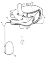
- Fig. 1
- a pacemaker lead as a connection between the actual pacemaker and the inside of a heart, where its electrode head is anchored in the heart tissue,
- Fig. 2
- 1, on an enlarged scale and in longitudinal section, an electrode head of a pacemaker lead according to FIG Electrode head engages and the rotary movement can be transmitted,
- Fig. 3
- a representation corresponding to FIG. 2, a modified stylet with a modified head acting inward as projections Engages indentations of the cavity and is suitable for pulling out the electrode head,
- Fig. 4
- 2 shows a view of the sleeve forming the cavity in the electrode head from its open side with a view of the two indentations forming the inward projections,
- Fig. 5
- 3 shows a longitudinal section of a modified electrode head which is connected in one piece to a sleeve which has an internal thread into which a tension element or stylet with a suitable counter thread can be inserted,
- Fig. 6
- 5 shows a representation corresponding to FIG. 5, the thread of the stylet being screwed into the internal thread of the sleeve of the electrode head and thus ready for the electrode head to be withdrawn,
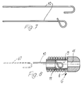
- Fig. 7
- a stiletto made of memory metal, the distal end of which is curved in a U-shape and forms a loop when heated, and
- Fig. 8
- a longitudinal section through an electrode head with an annular projection located in its sleeve, into which the stylet according to FIG. 7 can be inserted with its U-shaped curved end and which hooks behind the annular projection during the heating and deformation.
Eine im ganzen mit 1 bezeichnete Herzschrittmacherleitung hat eine Zuleitung 2, die aus einzelnen Windungen wendelförmig aufgebaut sein kann und von einem isolierenden Schlauch 3 überzogen sein kann. Die Zuleitung 2 verbindet dabei einen Herzschrittmacher 4 mit einem im Inneren des Herzens 5 in dessen Gewebe verankerbaren Elektrodenkopf 6, der gemäß den Figuren 2 und 3 oder 5 und 6 oder 8 unterschied-lich gestaltet sein kann, wobei weitere Abwandlungen dieses Elektrodenkopfes 6 möglich sind.A cardiac pacemaker lead, designated as a whole, has a
Im Ausführungsbeispiel nach den Figuren 2 und 3 hat der Elektrodenkopf 6 zu seiner Verankerung eine in das Gewebe eindrehbare Schraubwendel 7. Die Elektrodenköpfe 6 gemäß den Figuren 5 und 6 und 8 können sich mit einer Haltekante 8 innerhalb des Herzgewebes verhaken.In the exemplary embodiment according to FIGS. 2 and 3, the
Allen Ausführungsbeispielen ist gemeinsam, daß am distalen Ende der Herzschrittmacherleitung 1 ein zu dem Elektrodenkopf 6 gehöriger oder benachbarter Hohlraum 9 vorgesehen ist, der in axialer Richtung vom proximalen Ende der Herzschrittmacherleitung her zugänglich oder offen ist und eine im einzelnen bei den Ausführungsbeispielen jeweils noch zu beschreibende Kupplung für ein vom proximalen Ende der Herzschrittmacherleitung 1 einführbares Zugelement oder Stilett 10 hat. Dabei kann der im Bereich des Elektrodenkopfes 6 angeordnete Hohlraum 9 wenigstens einen, im Ausführungsbeispiel gemäß den Figuren 2 bis 4 zwei einander gegenüberliegende, in sein Inneres ragende Vorsprünge 11 und dadurch Hinterschneidungen haben und das Stilett 10, welches zum Aufbringen einer Zugkraft beim Entfernen des Elektrodenkopfes 6 aus dem Herzen 5 eingesetzt werden soll, weist ein hinter den oder die Vorsprünge 11 in die Hinterschneidung passendes Gegenstück 12 auf, welches durch Drehen in der Lage fixierbar und kuppelbar ist, in der dann Zugkräfte über das Stilett 10 auf den Elektrodenkopf 6 übertragen werden können. In Fig. 2 erkennt man zunächst ein übliches Stilett, welches zwischen die beiden Vorsprünge 11 paßt und zum Eindrehen der Schraubwendel 7 in das Herzgewebe dient. Der flache Kopf des Stilettes ist dabei so lang, daß er von dem distalen Ende des Hohlraumes 9 über die Vorsprünge 11 hinweg reicht.All of the exemplary embodiments have in common that at the distal end of the
Gemäß Fig. 3 ist das als Zugelement dienende Stilett 10 mit einem kürzeren Kopf 12 versehen, der nach dem Einschieben bis an das distale Ende oder die Stirnwand 13 des Hohlraumes 9 so verdreht werden kann, daß gemäß Fig. 3 dieser verbreiterte Kopf die Vorsprünge 11 hintergreift und nunmehr eine zugfeste Kupplung bildet. Vor allem Fig. 4 verdeutlicht, daß beim Einschieben des Stilettes 10 mit dem verbreiterten Kopf 12 in der einen Orientierungsrichtung dieser abgeflachte Kopf 12 problemlos zwischen den Vorsprüngen 11 hindurchgeschoben werden kann, wonach er um etwa 90o zu drehen ist, um die in Fig. 3 ersichtliche Gebrauchslage für die Aufbringung einer Rückzugkraft einzunehmen.According to FIG. 3, the
Die nach innen ragenden Vorsprünge 11 sind in diesem Ausführungsbeispiel Eindellungen, an denen der Kupplungskopf 12 des Stilettes 10 vorbeischiebbar ist, wonach er in der schon erwähnten Weise durch Drehung gekuppelt werden kann.In this exemplary embodiment, the inwardly projecting
Bei dem Ausführungsbeispiel nach den Figuren 5 und 6 ragen als Vorsprünge Gewindegänge in den Hohlraum 9 und das Zugelement oder Stilett 10 hat an seinem distalen Ende ein dazu passendes Gegengewinde 14, welches also durch Drehung mit dem Hohlraum 9 zugfest kuppelbar ist.In the embodiment according to FIGS. 5 and 6, threads protrude into the
Beim Ausführungsbeispiel nach den Figuren 7 und 8 besteht das Zugelement zumindest in seinem Kupplungsbereich aus Memory-Metall und ist in diesem Kupplungsbereich zunächst U-förmig derart gebogen, daß es durch den ringförmigen Kupplungsvorsprung 11 dieses Ausführungsbeispieles hindurch in einen erweiteren Bereich des Hohlraumes 9 einschiebbar ist. Durch Erwärmung verformt sich dann das Kupplungsende dieses Zugelementes in der dargestellten Weise zu einer Schlaufe, die den ringförmigen Kupplungsvorsprung 11 im Inneren des Hohlraumes 9 formschlüssig hintergreift, so daß auch in diesem Falle wiederum eine hohe Zugkraft unmittelbar auf den Elektrodenkopf 6 ausgeübt werden kann.In the embodiment according to FIGS. 7 and 8, the tension element consists at least in its coupling area of memory metal and is initially bent in a U-shape in this coupling area in such a way that it can be inserted into an enlarged area of the
Somit ist bei allen Ausführungsbeispielen möglich, eine implantierte Herzschrittmacherleitung 1 aus dem Herzen 5 herauszuziehen und dabei die Zugkraft unmittelbar am Elektrodenkopf 6 aufzubringen.It is thus possible in all exemplary embodiments to pull an implanted
Es sei noch erwähnt, daß der die Kupplung für das Zugelement aufweisende Hohlraum 9 in all diesen Ausführungsbeispielen als im distalen Endbereich des isolierenden überzuges oder Schlauches 3 der Herzschrittmacherleitung 1 angeordnete Hülse ausgebildet ist, an deren distalem Ende der eigentliche Elektrodenkopf oder die Einschraubwendel 7 befestigt ist. Somit erhält diese Hülse eine Doppelfunktion, weil sie einerseits die Verankerung des Elektrodenkopfes 6 trägt und andererseits den Hohlraum mit dem Kupplungsvorsprung für das Zugelement oder Stilett 10 bildet. In den Ausführungsbeispielen gemäß Fig. 5 bis 8 erkennt man am distalen Ende des Kupplungshohlraumes 9 eine Öffnung 15 zum Abgeben eines Medikamentes an das Herzgewebe, welches Medikament in dem Hohlraum 9 gespeichert werden kann oder durch den inneren Kanal 16 der Zuleitung 2 der Herzschrittmacherleitung 1 zugeführt werden kann. Auch an der stirnseitigen Wandung 13 der Hülse für den Hohlraum 11 gemäß den Figuren 2 und 3 könnte eine solche oder auch eine kleinere Öffnung 15 vorgesehen sein, um ein Medikament allmählich in das Herz abgeben zu können.It should also be mentioned that the
Bei allen Ausführungsbeispielen ist es möglich, die implantierte und an dem Elektrodenkopf 6 verankerte Herzschrittmacherleitung 1 aus dem Herzen herauszuziehen und dabei die Zugkraft unmittelbar an dem Elektrodenkopf 6 selbst aufzubringen, so daß die eigentliche Zuleitung 2 diese Zugkräfte nicht übertragen muß und die Verbindung zwischen der Zuleitung 2 und dem Elektrodenkopf 6 durch solche Zugkräfte nicht belastet und gefährtdet wird.
Die Herzschrittmacherleitung 1 mit einer Zuleitung 2 zwischen einem Herzschrittmacher 4 und einem Elektrodenkopf 6 zum Implantieren im Gewebe des Herzens 5 sowie einem inneren Kanal 16 für ein Stilett oder dergleichen hat am distalen Ende einen zu dem Elektrodenkopf 6 gehörigen Hohlraum 9, der in axialer Richtung vom proximalen Ende der Herzschrittmacherleitung 1 her durch den Kanal 16 zugänglich und offen ist und eine Kupplung für ein vom proximalen Ende her einführbares Zugelement oder Stilett 10 hat, so daß die Verankerung des Elektrodenkopfes 6 durch eine unmittelbar an ihm selbst aufgebrachte Zugkraft erforderlichenfalls gelöst werden kann, also keine Reißgefahr im Verlauf der Zuleitung 2 oder an deren Verbindung mit dem Elektrodenkopf 6 besteht. Dabei sind unterschiedliche Möglichkeiten einer Ausgestaltung der Kupplung vorzugsweise mit in das Innere des Hohlraumes 9 ragenden Vorsprüngen 11 möglich, mit denen ein entsprechendes Gegenstuck 12 an dem Zugelement oder Stilett 10 vor allem durch Drehung in Wirkverbindung gebracht werden können.In all embodiments, it is possible to use the implanted and pull the
The
Claims (9)
Priority Applications (4)
| Application Number | Priority Date | Filing Date | Title |
|---|---|---|---|
| DE59008908T DE59008908D1 (en) | 1990-12-19 | 1990-12-19 | Pacemaker lead with an inner channel and with an electrode head. |
| AT90124817T ATE120971T1 (en) | 1990-12-19 | 1990-12-19 | PACEMAKER LEAD WITH AN INNER CHANNEL AND WITH AN ELECTRODE HEAD. |
| EP90124817A EP0491082B1 (en) | 1990-12-19 | 1990-12-19 | Pacemaker lead with an inner duct and with an electrode head |
| US07/795,006 US5261419A (en) | 1990-12-19 | 1991-11-15 | Cardiac pacemaker lead |
Applications Claiming Priority (1)
| Application Number | Priority Date | Filing Date | Title |
|---|---|---|---|
| EP90124817A EP0491082B1 (en) | 1990-12-19 | 1990-12-19 | Pacemaker lead with an inner duct and with an electrode head |
Publications (2)
| Publication Number | Publication Date |
|---|---|
| EP0491082A1 true EP0491082A1 (en) | 1992-06-24 |
| EP0491082B1 EP0491082B1 (en) | 1995-04-12 |
Family
ID=8204869
Family Applications (1)
| Application Number | Title | Priority Date | Filing Date |
|---|---|---|---|
| EP90124817A Expired - Lifetime EP0491082B1 (en) | 1990-12-19 | 1990-12-19 | Pacemaker lead with an inner duct and with an electrode head |
Country Status (4)
| Country | Link |
|---|---|
| US (1) | US5261419A (en) |
| EP (1) | EP0491082B1 (en) |
| AT (1) | ATE120971T1 (en) |
| DE (1) | DE59008908D1 (en) |
Cited By (3)
| Publication number | Priority date | Publication date | Assignee | Title |
|---|---|---|---|---|
| US5374287A (en) * | 1991-04-10 | 1994-12-20 | British Technology Group Usa Inc. | Defibrillator and demand pacer catheters and methods for using same |
| FR2733429A1 (en) * | 1995-04-28 | 1996-10-31 | Dev Sed Soc Et | DEVICE FOR HANDLING AND SETTING UP A HEART STIMULATION APPARATUS ELECTRODE |
| US5851227A (en) * | 1997-07-30 | 1998-12-22 | Sulzer Intermedics Inc. | Cardiac pacemaker cable lead |
Families Citing this family (46)
| Publication number | Priority date | Publication date | Assignee | Title |
|---|---|---|---|---|
| US5769858A (en) * | 1995-10-20 | 1998-06-23 | Medtronic, Inc. | Locking stylet for extracting implantable lead or catheter |
| US5755762A (en) * | 1996-06-14 | 1998-05-26 | Pacesetter, Inc. | Medical lead and method of making and using |
| US5851226A (en) | 1996-10-22 | 1998-12-22 | Medtronic, Inc. | Temporary transvenous endocardial lead |
| US6501993B2 (en) | 2001-03-27 | 2002-12-31 | Pacesetter, Inc. | Electrode assembly with a detachable distal tip |
| RU2341296C2 (en) | 2002-05-24 | 2008-12-20 | Энджиотек Интернэшнл Аг | Compositions and methods of medical implant covering |
| US6944506B1 (en) * | 2002-06-25 | 2005-09-13 | Pacesetter, Inc. | Stylet feature for resisting perforation of an implantable lead |
| US7103418B2 (en) * | 2002-10-02 | 2006-09-05 | Medtronic, Inc. | Active fluid delivery catheter |
| FR2846639B1 (en) * | 2002-11-06 | 2004-12-10 | Innovation Packaging | PACKAGING AND DISPENSING DEVICE FOR A LIQUID OR SEMI-LIQUID PRODUCT |
| EP1558332A2 (en) * | 2002-11-07 | 2005-08-03 | Axiom Medical Inc. | Epicardial heartwire, chest tube with epicardial heartwire, and method of use |
| US7962208B2 (en) | 2005-04-25 | 2011-06-14 | Cardiac Pacemakers, Inc. | Method and apparatus for pacing during revascularization |
| WO2006138380A2 (en) | 2005-06-15 | 2006-12-28 | Massachusetts Institute Of Technology | Amine-containing lipids and uses thereof |
| US8019438B2 (en) * | 2005-06-28 | 2011-09-13 | Cardiac Pacemakers, Inc. | Anchor for electrode delivery system |
| US20070055334A1 (en) * | 2005-08-23 | 2007-03-08 | Cardiac Pacemakers, Inc. | Cardiac lead and stylet assembly |
| US7885710B2 (en) | 2005-12-23 | 2011-02-08 | Cardiac Pacemakers, Inc. | Method and apparatus for tissue protection against ischemia using remote conditioning |
| US8918193B2 (en) * | 2006-08-16 | 2014-12-23 | Vahe S. Yacoubian | Heart wire |
| US9037235B2 (en) | 2008-06-19 | 2015-05-19 | Cardiac Pacemakers, Inc. | Pacing catheter with expandable distal end |
| US8244352B2 (en) | 2008-06-19 | 2012-08-14 | Cardiac Pacemakers, Inc. | Pacing catheter releasing conductive liquid |
| US9409012B2 (en) | 2008-06-19 | 2016-08-09 | Cardiac Pacemakers, Inc. | Pacemaker integrated with vascular intervention catheter |
| US8457738B2 (en) | 2008-06-19 | 2013-06-04 | Cardiac Pacemakers, Inc. | Pacing catheter for access to multiple vessels |
| US8639357B2 (en) | 2008-06-19 | 2014-01-28 | Cardiac Pacemakers, Inc. | Pacing catheter with stent electrode |
| WO2010002456A1 (en) * | 2008-07-01 | 2010-01-07 | Cardiac Pacemakers, Inc. | Pacing system controller integrated into indeflator |
| CA3006395C (en) | 2008-11-07 | 2022-05-31 | Massachusetts Institute Of Technology | Aminoalcohol lipidoids and uses thereof |
| US20110106099A1 (en) * | 2009-10-29 | 2011-05-05 | Medtronic, Inc. | Lead extraction device |
| NZ716192A (en) | 2009-12-01 | 2017-07-28 | Shire Human Genetic Therapies | Delivery of mrna for the augmentation of proteins and enzymes in human genetic diseases |
| US9193827B2 (en) | 2010-08-26 | 2015-11-24 | Massachusetts Institute Of Technology | Poly(beta-amino alcohols), their preparation, and uses thereof |
| DK2691443T3 (en) | 2011-03-28 | 2021-05-03 | Massachusetts Inst Technology | CONJUGIATED LIPOMERS AND USES OF THESE |
| DK2717893T3 (en) | 2011-06-08 | 2019-07-22 | Translate Bio Inc | Lipid Nanoparticle Compositions and Procedures for MRNA Delivery |
| WO2013185067A1 (en) | 2012-06-08 | 2013-12-12 | Shire Human Genetic Therapies, Inc. | Nuclease resistant polynucleotides and uses thereof |
| UA117008C2 (en) | 2013-03-14 | 2018-06-11 | Шир Хьюман Дженетік Терапіс, Інк. | CFTR mRNA COMPOSITIONS AND RELATED METHODS AND USES |
| DK3467108T3 (en) | 2013-03-14 | 2024-06-10 | Translate Bio Inc | Methods for purifying messenger RNA |
| WO2014179562A1 (en) | 2013-05-01 | 2014-11-06 | Massachusetts Institute Of Technology | 1,3,5-triazinane-2,4,6-trione derivatives and uses thereof |
| EA201992208A1 (en) | 2013-10-22 | 2020-07-31 | Транслейт Био, Инк. | TREATMENT OF PHENYLKETONURIA USING mRNA |
| EP3060303B1 (en) | 2013-10-22 | 2018-11-14 | Translate Bio, Inc. | Mrna therapy for argininosuccinate synthetase deficiency |
| EP3060257B1 (en) | 2013-10-22 | 2021-02-24 | Translate Bio, Inc. | Lipid formulations for delivery of messenger rna |
| JP6571679B2 (en) | 2014-04-25 | 2019-09-04 | トランスレイト バイオ, インコーポレイテッド | Method for purifying messenger RNA |
| JP6557722B2 (en) | 2014-05-30 | 2019-08-07 | シャイアー ヒューマン ジェネティック セラピーズ インコーポレイテッド | Biodegradable lipids for delivery of nucleic acids |
| ES2964588T3 (en) | 2014-06-24 | 2024-04-08 | Translate Bio Inc | Stereochemically enriched compositions for nucleic acid delivery |
| US9840479B2 (en) | 2014-07-02 | 2017-12-12 | Massachusetts Institute Of Technology | Polyamine-fatty acid derived lipidoids and uses thereof |
| CA3054062A1 (en) | 2017-02-27 | 2018-08-30 | Translate Bio, Inc. | Novel codon-optimized cftr mrna |
| EP3624824B1 (en) | 2017-05-16 | 2024-07-10 | Translate Bio, Inc. | Codon-optimized mrna encoding cftr for use in treating cystic fibrosis |
| US10933247B2 (en) | 2017-08-21 | 2021-03-02 | MRM MedTech, LLC | Lead with integrated features to facilitate extraction and associated methods of extraction |
| US11865334B2 (en) | 2017-08-21 | 2024-01-09 | MRM MedTech, LLC | Lead with integrated feature including a low friction component to facilitate extraction and associated methods of extraction |
| CN118421617A (en) | 2018-08-24 | 2024-08-02 | 川斯勒佰尔公司 | Method for purifying messenger RNA |
| KR102137740B1 (en) * | 2018-11-15 | 2020-07-24 | (주) 타우피엔유메디칼 | Pacemaker lead for cerclage pacing |
| CN109568793B (en) * | 2018-12-25 | 2023-08-04 | 创领心律管理医疗器械(上海)有限公司 | Leadless pacemaker and leadless pacing system |
| KR20220091583A (en) * | 2019-11-05 | 2022-06-30 | 보스톤 싸이엔티픽 싸이메드 인코포레이티드 | Tissue Capture Spiral Device |
Citations (3)
| Publication number | Priority date | Publication date | Assignee | Title |
|---|---|---|---|---|
| EP0047013A1 (en) * | 1980-09-02 | 1982-03-10 | Medtronic, Inc. | Subcutaneously implantable lead with drug dispenser means |
| EP0282047A2 (en) * | 1987-03-13 | 1988-09-14 | Hans-Jürgen Dipl.-Ing. Bisping | Implantable probe with a protrudable cork screw electrode |
| EP0368568A2 (en) * | 1988-11-09 | 1990-05-16 | Med Institute, Inc. | Apparatus for removing an elongated structure implanted in biological tissue |
Family Cites Families (5)
| Publication number | Priority date | Publication date | Assignee | Title |
|---|---|---|---|---|
| DE2539553A1 (en) * | 1975-09-05 | 1977-03-10 | Osypka Peter | ELECTRODE ARRANGEMENT FOR MEDICAL PURPOSES |
| USRE32227E (en) * | 1981-03-19 | 1986-08-19 | Medtronic, Inc. | "J" Stylet wire |
| DE3146182C2 (en) * | 1981-11-21 | 1984-03-29 | Peter Dr. 7889 Grenzach-Wyhlen Osypka | Electrode arrangement for a cardiac pacemaker that can be inserted transvenously into the heart |
| US4924881A (en) * | 1989-05-12 | 1990-05-15 | Intermedics, Inc. | Implantable endocardial lead with fixation device retractable by threaded stylet |
| US5003992A (en) * | 1989-08-23 | 1991-04-02 | Holleman Timothy W | Atraumatic screw-in lead |
-
1990
- 1990-12-19 DE DE59008908T patent/DE59008908D1/en not_active Expired - Fee Related
- 1990-12-19 EP EP90124817A patent/EP0491082B1/en not_active Expired - Lifetime
- 1990-12-19 AT AT90124817T patent/ATE120971T1/en active
-
1991
- 1991-11-15 US US07/795,006 patent/US5261419A/en not_active Expired - Fee Related
Patent Citations (3)
| Publication number | Priority date | Publication date | Assignee | Title |
|---|---|---|---|---|
| EP0047013A1 (en) * | 1980-09-02 | 1982-03-10 | Medtronic, Inc. | Subcutaneously implantable lead with drug dispenser means |
| EP0282047A2 (en) * | 1987-03-13 | 1988-09-14 | Hans-Jürgen Dipl.-Ing. Bisping | Implantable probe with a protrudable cork screw electrode |
| EP0368568A2 (en) * | 1988-11-09 | 1990-05-16 | Med Institute, Inc. | Apparatus for removing an elongated structure implanted in biological tissue |
Cited By (5)
| Publication number | Priority date | Publication date | Assignee | Title |
|---|---|---|---|---|
| US5374287A (en) * | 1991-04-10 | 1994-12-20 | British Technology Group Usa Inc. | Defibrillator and demand pacer catheters and methods for using same |
| US5476502A (en) * | 1991-04-10 | 1995-12-19 | British Technology Group Usa Inc. | Defibrillator and demand pacer catheters and methods for using same |
| FR2733429A1 (en) * | 1995-04-28 | 1996-10-31 | Dev Sed Soc Et | DEVICE FOR HANDLING AND SETTING UP A HEART STIMULATION APPARATUS ELECTRODE |
| EP0740943A1 (en) * | 1995-04-28 | 1996-11-06 | Societe Etudes Et Developpements S.E.D. | Handling and positioning device for an electrode included in a pacemaker apparatus |
| US5851227A (en) * | 1997-07-30 | 1998-12-22 | Sulzer Intermedics Inc. | Cardiac pacemaker cable lead |
Also Published As
| Publication number | Publication date |
|---|---|
| US5261419A (en) | 1993-11-16 |
| ATE120971T1 (en) | 1995-04-15 |
| DE59008908D1 (en) | 1995-05-18 |
| EP0491082B1 (en) | 1995-04-12 |
Similar Documents
| Publication | Publication Date | Title |
|---|---|---|
| EP0491082B1 (en) | Pacemaker lead with an inner duct and with an electrode head | |
| EP0792129B1 (en) | Modular joint prosthesis | |
| DE69819913T2 (en) | SEWING CUFF WITH LOCKABLE CIRCULAR THREAD | |
| EP0348692B1 (en) | Device for entering a vein or artery by means of a guide wire | |
| DE69624008T2 (en) | FLAT MARKEL NAIL | |
| EP0513943B1 (en) | Implant with pressure surface | |
| EP0592897B1 (en) | Modular shaft for a hip prothesis | |
| DE69519732T2 (en) | Bone screw with reversible closure | |
| DE10316177B4 (en) | Pacemaker electrode arrangement | |
| EP0795344B1 (en) | Implantable device | |
| DE1054659B (en) | Tubular bone nail | |
| DE2112138B1 (en) | Sleeve-shaped support element for tubular bone fractures | |
| DE102006026590B3 (en) | implant | |
| EP1321165A2 (en) | Epicardial electrode lead, insertion catheter for the same and electrode implantation device | |
| DE3146182C2 (en) | Electrode arrangement for a cardiac pacemaker that can be inserted transvenously into the heart | |
| DE2755179A1 (en) | DEVICE FOR ATTACHING A MEASURING HEAD | |
| AT395940B (en) | BONE NAIL AND TOOL FOR THE SAME | |
| DE202005022017U1 (en) | Bone Anchor with threaded structure optimized for fixation in cortical bone tissue and cancellous bone tissue | |
| DE2533766A1 (en) | TRANSVENOESIS, IMPLANTABLE PACEMAKER ELECTRODE | |
| EP1064885A1 (en) | Spinal fixator | |
| DE102008005378B4 (en) | Implantable bipolar electrode | |
| EP0219608A2 (en) | Intravenously insertable heart pacemaker lead | |
| WO2002080790A1 (en) | Bone nail for surgical purposes | |
| DE2359644A1 (en) | Osteosynthesis nail with guide wire lance - has spreader body at end of constantly widening cross section | |
| DE102008005377A1 (en) | Bipolar electrode |
Legal Events
| Date | Code | Title | Description |
|---|---|---|---|
| PUAI | Public reference made under article 153(3) epc to a published international application that has entered the european phase |
Free format text: ORIGINAL CODE: 0009012 |
|
| 17P | Request for examination filed |
Effective date: 19911004 |
|
| AK | Designated contracting states |
Kind code of ref document: A1 Designated state(s): AT CH DE ES FR GB IT LI NL SE |
|
| 17Q | First examination report despatched |
Effective date: 19940201 |
|
| GRAA | (expected) grant |
Free format text: ORIGINAL CODE: 0009210 |
|
| AK | Designated contracting states |
Kind code of ref document: B1 Designated state(s): AT CH DE ES FR GB IT LI NL SE |
|
| PG25 | Lapsed in a contracting state [announced via postgrant information from national office to epo] |
Ref country code: ES Free format text: THE PATENT HAS BEEN ANNULLED BY A DECISION OF A NATIONAL AUTHORITY Effective date: 19950412 |
|
| REF | Corresponds to: |
Ref document number: 120971 Country of ref document: AT Date of ref document: 19950415 Kind code of ref document: T |
|
| REF | Corresponds to: |
Ref document number: 59008908 Country of ref document: DE Date of ref document: 19950518 |
|
| ITF | It: translation for a ep patent filed | ||
| GBT | Gb: translation of ep patent filed (gb section 77(6)(a)/1977) |
Effective date: 19950612 |
|
| PG25 | Lapsed in a contracting state [announced via postgrant information from national office to epo] |
Ref country code: SE Effective date: 19950712 |
|
| ET | Fr: translation filed | ||
| PLBI | Opposition filed |
Free format text: ORIGINAL CODE: 0009260 |
|
| PLBF | Reply of patent proprietor to notice(s) of opposition |
Free format text: ORIGINAL CODE: EPIDOS OBSO |
|
| 26 | Opposition filed |
Opponent name: BIOTRONIK MESS- UND THERAPIEGERAETE GMBH & CO INGE Effective date: 19960108 |
|
| PLBF | Reply of patent proprietor to notice(s) of opposition |
Free format text: ORIGINAL CODE: EPIDOS OBSO |
|
| NLR1 | Nl: opposition has been filed with the epo |
Opponent name: BIOTRONIK MESS- UND THERAPIEGERAETE GMBH & CO INGE |
|
| PLBQ | Unpublished change to opponent data |
Free format text: ORIGINAL CODE: EPIDOS OPPO |
|
| PGFP | Annual fee paid to national office [announced via postgrant information from national office to epo] |
Ref country code: FR Payment date: 19981013 Year of fee payment: 9 |
|
| PGFP | Annual fee paid to national office [announced via postgrant information from national office to epo] |
Ref country code: DE Payment date: 19981028 Year of fee payment: 9 |
|
| PGFP | Annual fee paid to national office [announced via postgrant information from national office to epo] |
Ref country code: GB Payment date: 19981215 Year of fee payment: 9 |
|
| PGFP | Annual fee paid to national office [announced via postgrant information from national office to epo] |
Ref country code: CH Payment date: 19981216 Year of fee payment: 9 |
|
| PGFP | Annual fee paid to national office [announced via postgrant information from national office to epo] |
Ref country code: AT Payment date: 19981229 Year of fee payment: 9 |
|
| PGFP | Annual fee paid to national office [announced via postgrant information from national office to epo] |
Ref country code: NL Payment date: 19981231 Year of fee payment: 9 |
|
| PLBL | Opposition procedure terminated |
Free format text: ORIGINAL CODE: EPIDOS OPPC |
|
| PLBQ | Unpublished change to opponent data |
Free format text: ORIGINAL CODE: EPIDOS OPPO |
|
| PLAB | Opposition data, opponent's data or that of the opponent's representative modified |
Free format text: ORIGINAL CODE: 0009299OPPO |
|
| PLBM | Termination of opposition procedure: date of legal effect published |
Free format text: ORIGINAL CODE: 0009276 |
|
| STAA | Information on the status of an ep patent application or granted ep patent |
Free format text: STATUS: OPPOSITION PROCEDURE CLOSED |
|
| PG25 | Lapsed in a contracting state [announced via postgrant information from national office to epo] |
Ref country code: GB Free format text: LAPSE BECAUSE OF NON-PAYMENT OF DUE FEES Effective date: 19991219 Ref country code: AT Free format text: LAPSE BECAUSE OF NON-PAYMENT OF DUE FEES Effective date: 19991219 |
|
| PG25 | Lapsed in a contracting state [announced via postgrant information from national office to epo] |
Ref country code: LI Free format text: LAPSE BECAUSE OF NON-PAYMENT OF DUE FEES Effective date: 19991231 Ref country code: CH Free format text: LAPSE BECAUSE OF NON-PAYMENT OF DUE FEES Effective date: 19991231 |
|
| 27C | Opposition proceedings terminated |
Effective date: 19990826 |
|
| NLR2 | Nl: decision of opposition | ||
| PG25 | Lapsed in a contracting state [announced via postgrant information from national office to epo] |
Ref country code: NL Free format text: LAPSE BECAUSE OF NON-PAYMENT OF DUE FEES Effective date: 20000701 |
|
| GBPC | Gb: european patent ceased through non-payment of renewal fee |
Effective date: 19991219 |
|
| PG25 | Lapsed in a contracting state [announced via postgrant information from national office to epo] |
Ref country code: FR Free format text: LAPSE BECAUSE OF NON-PAYMENT OF DUE FEES Effective date: 20000831 |
|
| NLV4 | Nl: lapsed or anulled due to non-payment of the annual fee |
Effective date: 20000701 |
|
| PG25 | Lapsed in a contracting state [announced via postgrant information from national office to epo] |
Ref country code: DE Free format text: LAPSE BECAUSE OF NON-PAYMENT OF DUE FEES Effective date: 20001003 |
|
| REG | Reference to a national code |
Ref country code: FR Ref legal event code: ST |
|
| PG25 | Lapsed in a contracting state [announced via postgrant information from national office to epo] |
Ref country code: IT Free format text: LAPSE BECAUSE OF NON-PAYMENT OF DUE FEES;WARNING: LAPSES OF ITALIAN PATENTS WITH EFFECTIVE DATE BEFORE 2007 MAY HAVE OCCURRED AT ANY TIME BEFORE 2007. THE CORRECT EFFECTIVE DATE MAY BE DIFFERENT FROM THE ONE RECORDED. Effective date: 20051219 |