EP0490604A2 - Appareil de balayage optique - Google Patents
Appareil de balayage optique Download PDFInfo
- Publication number
- EP0490604A2 EP0490604A2 EP91311411A EP91311411A EP0490604A2 EP 0490604 A2 EP0490604 A2 EP 0490604A2 EP 91311411 A EP91311411 A EP 91311411A EP 91311411 A EP91311411 A EP 91311411A EP 0490604 A2 EP0490604 A2 EP 0490604A2
- Authority
- EP
- European Patent Office
- Prior art keywords
- light
- light beams
- mirrors
- scanning
- drive shaft
- Prior art date
- Legal status (The legal status is an assumption and is not a legal conclusion. Google has not performed a legal analysis and makes no representation as to the accuracy of the status listed.)
- Granted
Links
Images


Classifications
-
- G—PHYSICS
- G06—COMPUTING; CALCULATING OR COUNTING
- G06K—GRAPHICAL DATA READING; PRESENTATION OF DATA; RECORD CARRIERS; HANDLING RECORD CARRIERS
- G06K7/00—Methods or arrangements for sensing record carriers, e.g. for reading patterns
- G06K7/10—Methods or arrangements for sensing record carriers, e.g. for reading patterns by electromagnetic radiation, e.g. optical sensing; by corpuscular radiation
- G06K7/10544—Methods or arrangements for sensing record carriers, e.g. for reading patterns by electromagnetic radiation, e.g. optical sensing; by corpuscular radiation by scanning of the records by radiation in the optical part of the electromagnetic spectrum
- G06K7/10821—Methods or arrangements for sensing record carriers, e.g. for reading patterns by electromagnetic radiation, e.g. optical sensing; by corpuscular radiation by scanning of the records by radiation in the optical part of the electromagnetic spectrum further details of bar or optical code scanning devices
- G06K7/10861—Methods or arrangements for sensing record carriers, e.g. for reading patterns by electromagnetic radiation, e.g. optical sensing; by corpuscular radiation by scanning of the records by radiation in the optical part of the electromagnetic spectrum further details of bar or optical code scanning devices sensing of data fields affixed to objects or articles, e.g. coded labels
- G06K7/10871—Methods or arrangements for sensing record carriers, e.g. for reading patterns by electromagnetic radiation, e.g. optical sensing; by corpuscular radiation by scanning of the records by radiation in the optical part of the electromagnetic spectrum further details of bar or optical code scanning devices sensing of data fields affixed to objects or articles, e.g. coded labels randomly oriented data-fields, code-marks therefore, e.g. concentric circles-code
Definitions
- the present invention relates to optical scanning apparatus and in particular, but not exclusively, to an optical bar code scanning system which can be mounted within a checkout counter or other type of support member for scanning bar code labels on a merchandise item which is moved past a scanning aperture located in the bar code scanner.
- data pertaining to the purchase of a merchandise item is obtained by reading data encoded indicia such as a bar code printed on the merchandise item.
- data encoded indicia such as a bar code printed on the merchandise item.
- UPC uniform product code
- Various reading systems have been constructed to read this type of bar code, including hand-held scanners which are moved across the bar code and stationary optical reader systems normally located within the checkout counter in which the bar code is read by projecting a plurality of scanning light beams through a window constituting the scanning area of the counter over which a bar code printed on a purchased merchandise item or on a bar code label attached to the merchandise item is moved.
- This scanning operation is part of the process of loading the item into a baggage cart.
- a scan pattern is generated by the scanning apparatus which consists of a plurality of individual scanning lines oriented in various directions so as to enable the scan pattern to scan the bar code label irrespective of its orientation with respect to the scan pattern.
- the most common prior art scan pattern is in the form of an X together with an horizontal line.
- scanning systems currently found in checkout counters comprise a disadvantageously large structure mounted within the counter which have a number of mirrors mounted so as to occupy the internal area of the checkout counter.
- the present invention accordingly seeks to provide a compact optical scanner which is not only low in cost does not occupy a large portion of the checkout counter, but which has the particular advantage of producing a scanning pattern composed of dense pattern of scan lines.
- an optical scanning apparatus comprising a light source for projecting light on to first deflecting means mounted on a rotatable drive member for rotation therewith in a first direction, characterized by second deflecting means arranged to rotate in a direction opposite to that of said first deflecting means and comprising a first plurality of mirror members conically arranged around said first defecting means to receive light deflected by said first defecting means, and a second plurality of mirror members arranged to receive light deflected by said first plurality of mirror members and to deflect this light so as to form a scan pattern for scanning coded indicia.
- an optical scanning unit which can be mounted adjacent the top surface of a checkout counter or any other type of support member which includes a laser source for projecting laser light beams through the hollow drive shaft of a motor which is mounted for support on a printed circuit board.
- the motor can support a ring shape base support member on which is mounted by means of a plurality of bearing members, a ring support member which includes a plurality of arm members for supporting a conical shaped ring of deflecting mirrors enclosing the motor and the drive shaft.
- a deflecting member for deflecting the laser light beam outwardly to the ring of mirrors which in turn deflect the laser light beams in a downward direction to a circular ring member.
- the circular ring member deflects the laser light beams at a ring of vertically oriented pattern forming mirror members which deflect the received light beams through an aperture in the top of the checkout counter in a scanning direction for scanning a bar code label positioned in a scanning zone adjacent the aperture.
- a gear member can be secured to the drive shaft engages a drive gear supported on the base member which engages the internal teeth of the ring support member for rotating the ring support member together with the ring of mirrors in a direction opposite to the direction of rotation of the drive shaft and the deflecting member.
- the invention advantageously provides for the generation of a scan pattern comprising a large number of rectilinear lines producing a highly dense scan pattern which is rotated in a circular direction enabling the scan pattern to scan a bar code label irrespective of its orientation.
- the optical scanning apparatus which generates a highly dense scan pattern comprising a plurality of straight scan lines oriented in a direction perpendicular to each other, while also providing an optical scanner which is compact in structure enabling the scanner to be installed in a very small supporting member and which is simple in construction and therefore low in cost.
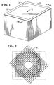
- FIG. 1 there is shown a perspective view of a housing member 20 in which is located the optical scanning apparatus of the present invention.
- the housing member 20 includes an aperture 22 located in the cover portion 23 of the housing member in which is mounted a transparent cover member 24 such as a glass window through which are projected the scanning light beams generated by the scanning apparatus of the present invention.
- an optical scanning apparatus generally indicated by the numeral 26 which includes a printed circuit board 28 mounted to the floor portion 30 of the enclosure 20 by means of studs 31.
- a ring shaped reflecting mirror member 32 (Fig. 8) which encircles a motor member 34 mounted on a hollow support member 36 secured to the printed circuit board 28.
- the motor member 34 rotates a hollow drive shaft 40 in a manner that is well known in the art.
- the drive shaft 40 is mounted on two bearing members 42 mounted within the motor member 34.
- Mounted to the motor member 34 by means of screws 44 (Figs. 3 and 7) is a circular base plate member 46 (Fig. 7) which includes a circular slot 48 extending along the outer parameter of the plate member 46.
- a plurality of needle bearing members 50 which slidably support a ring member 52 (Fig. 6) having its inner circumferential surface comprised of gear teeth 54.
- a drive member 56 (Figs. 3 and 6) which engages a second gear member 58 rotatably secured to the motor member 34 by means of a pin member 59 in the plate member 46, the gear member 58 engaging the gear teeth 54 of the ring member 52.
- optical transceiver 64 which includes a deflecting portion 66 and a collection portion 68.
- the laser diode member 70 outputs a diverging light beam which is collimated and focused on a reference plane (not shown) in front of the glass window 24 by the lens member 72.
- a photodetector 76 Secured to the glass window 24 in any conventional manner such as an adhesive coating is a photodetector 76 which, as will be described more fully hereafter, receives the light beams reflected from a scanned bar code label for generating electrical signals in response to the intensity of the reflective light beams received.
- a scanning pattern 84 (Fig. 2) which is composed of a plurality of rectilinear scanning lines.
- the motor member 34 is a 5-volt brushless DC motor which rotates the drive shaft at a speed of approximately 3200 rpm.
- the rotational movement of the drive shaft 40 will be transmitted through the gear members 56 and 58 to the ring member 52, rotating the ring member in a direction which is opposite to that of the rotation of the drive shaft 40.
- the laser diode member 70 will output a laser light beam through the drive shaft 40 which is deflected 90 degrees by the deflecting portion 66 of the optical transceiver 64.
- the light beams reflected by the deflecting portion 66 of the transceiver will strike the interior surface of the rotating mirror members 62, deflecting the light beams in a downward direction along a plurality of light paths 67 (Fig. 4) to strike the mirror member 32.
- the mirror member 32 deflects the light beams towards the pattern forming mirror members 82 which in turn deflect the received light beams through the glass window 24 in the aperture 22 in the form of the scan pattern 84 (Fig. 2) through which a bar code label is passed adjacent the glass window 24.
- the light beams reflected from the scanned bar code label are transmitted through the glass window 24 along light paths which are collected by the collection portion 68 of the optical transceiver 64 for focusing the reflected light beams on the photodetector 76. It will be seen from this arrangement that the reflected light beams are also directed towards the top opening of the ring 61 of mirror members 62 to be collected by the collection portion 68 of the transceiver 64 which is mounted adjacent the top opening of the ring of mirrors.
- the scan pattern 84 (Fig. 2) generated by the scanning apparatus of the present invention is the equivalent of 64 scan lines; 8 scan lines from 8 directions and from around 360 degrees assuming the use of eight pattern forming mirrors members 82 and eight mirror members 62 forming the ring 61.
- the exiting angles may vary between 40 and 90 degrees.
- the exiting scan lines in the scan pattern 84 from the top of the scanning apparatus are full length to give a large scan volume measured from the front of the scanning apparatus.
- a consideration of the present invention is that the 8/8 mirror arrangement will result in a plurality of partial scan lines as the full pattern effectively rotates around the drive shaft 40 as illustrated in Fig. 2.
- a wider scanning pattern is possible with different arrangement of the pattern mirror members 82 and the use of multiple bottom mirrors in place of the mirror member 32. While the present invention is shown disclosed in a portable housing member 20, it is obvious that the scanning apparatus can be mounted within a checkout counter as is normal in such checkout installations.
Landscapes
- Physics & Mathematics (AREA)
- Electromagnetism (AREA)
- Engineering & Computer Science (AREA)
- Health & Medical Sciences (AREA)
- General Health & Medical Sciences (AREA)
- Toxicology (AREA)
- Artificial Intelligence (AREA)
- Computer Vision & Pattern Recognition (AREA)
- General Physics & Mathematics (AREA)
- Theoretical Computer Science (AREA)
- Mechanical Optical Scanning Systems (AREA)
Applications Claiming Priority (2)
| Application Number | Priority Date | Filing Date | Title |
|---|---|---|---|
| US625323 | 1990-12-10 | ||
| US07/625,323 US5149949A (en) | 1990-12-10 | 1990-12-10 | Optical scanner with counterrotating reflector elements |
Publications (3)
| Publication Number | Publication Date |
|---|---|
| EP0490604A2 true EP0490604A2 (fr) | 1992-06-17 |
| EP0490604A3 EP0490604A3 (en) | 1993-04-21 |
| EP0490604B1 EP0490604B1 (fr) | 1996-05-15 |
Family
ID=24505537
Family Applications (1)
| Application Number | Title | Priority Date | Filing Date |
|---|---|---|---|
| EP91311411A Expired - Lifetime EP0490604B1 (fr) | 1990-12-10 | 1991-12-09 | Appareil de balayage optique |
Country Status (5)
| Country | Link |
|---|---|
| US (1) | US5149949A (fr) |
| EP (1) | EP0490604B1 (fr) |
| JP (1) | JPH04291475A (fr) |
| CA (1) | CA2041958A1 (fr) |
| DE (1) | DE69119564T2 (fr) |
Cited By (1)
| Publication number | Priority date | Publication date | Assignee | Title |
|---|---|---|---|---|
| EP0751472A1 (fr) * | 1995-06-26 | 1997-01-02 | Opticon Sensors Europe B.V. | Dispositif de balayage optique pour générer des lignes de balayage perpendiculaires |
Families Citing this family (21)
| Publication number | Priority date | Publication date | Assignee | Title |
|---|---|---|---|---|
| US5988508A (en) * | 1990-05-08 | 1999-11-23 | Symbol Technologies, Inc. | Laser scanning system and scanning method for reading 1-D and 2-D barcode symbols |
| US5581067A (en) * | 1990-05-08 | 1996-12-03 | Symbol Technologies, Inc. | Compact bar code scanning module with shock protection |
| US6390370B1 (en) | 1990-11-15 | 2002-05-21 | Symbol Technologies, Inc. | Light beam scanning pen, scan module for the device and method of utilization |
| US5506394A (en) * | 1990-11-15 | 1996-04-09 | Gap Technologies, Inc. | Light beam scanning pen, scan module for the device and method of utilization |
| US5371347A (en) * | 1991-10-15 | 1994-12-06 | Gap Technologies, Incorporated | Electro-optical scanning system with gyrating scan head |
| US6382513B1 (en) * | 1991-07-25 | 2002-05-07 | Symbol Technologies, Inc. | Optical scanner with segmented collection mirror |
| US6948662B2 (en) * | 1991-07-25 | 2005-09-27 | Symbol Technologies, Inc. | Two-dimensional optical code scanner with scanning pattern having region of greater apparent brightness for assisting alignment of scanning pattern |
| AU4282593A (en) | 1992-04-17 | 1993-11-18 | Spectra-Physics Scanning Systems, Inc. | Ultra-compact bar-code scanner |
| NL1003957C2 (nl) * | 1996-02-26 | 1997-08-27 | Scantech Bv | Inrichting voor het aftasten van barcodes. |
| US5914479A (en) * | 1996-09-20 | 1999-06-22 | Dynetics, Inc. | Counter-rotating scanner |
| US6144880A (en) * | 1998-05-08 | 2000-11-07 | Cardiac Pacemakers, Inc. | Cardiac pacing using adjustable atrio-ventricular delays |
| US6481626B1 (en) * | 1998-12-09 | 2002-11-19 | Ncr Corporation | Flush scanner window |
| US6382514B1 (en) * | 2000-06-29 | 2002-05-07 | Kuo-Ming Chung | Scanning device for bar-code scanner |
| US7116906B2 (en) * | 2001-03-06 | 2006-10-03 | Incucomm, Inc. | Wireless optical system for high bandwidth communications |
| US6804465B2 (en) * | 2001-03-06 | 2004-10-12 | Incucomm, Inc. | Wireless optical system for multidirectional high bandwidth communications |
| US20040057730A1 (en) * | 2002-09-18 | 2004-03-25 | Harry Littlejohn | Control processor for use with a transceiver in an optical wireless network |
| US6883712B1 (en) * | 2002-12-19 | 2005-04-26 | Ncr Corporation | Bar code scanner |
| US6905070B1 (en) * | 2002-12-19 | 2005-06-14 | Ncr Corporation | Bar code scanner |
| US7111785B2 (en) * | 2003-06-05 | 2006-09-26 | Symbol Technologies, Inc. | Compact, omni-directional scan pattern generator and method in a reader for electro-optically reading indicia |
| US7044376B2 (en) * | 2003-07-23 | 2006-05-16 | Eastman Kodak Company | Authentication method and apparatus for use with compressed fluid printed swatches |
| US11062103B2 (en) * | 2019-06-03 | 2021-07-13 | Zebra Technologies Corporation | Digital barcode reader |
Citations (2)
| Publication number | Priority date | Publication date | Assignee | Title |
|---|---|---|---|---|
| EP0260155A2 (fr) * | 1986-09-12 | 1988-03-16 | Spectra-Physics, Inc. | Dispositif peu profond de balayage de codes à barres |
| US4971410A (en) * | 1989-07-27 | 1990-11-20 | Ncr Corporation | Scanning and collection system for a compact laser |
Family Cites Families (15)
| Publication number | Priority date | Publication date | Assignee | Title |
|---|---|---|---|---|
| US2997539A (en) * | 1953-04-16 | 1961-08-22 | Servo Corp Of America | Scanning mechanism |
| US3632871A (en) * | 1969-04-25 | 1972-01-04 | Raytheon Co | Optical scanning device |
| NL164685C (nl) * | 1974-02-26 | 1981-01-15 | Matsushita Electric Ind Co Ltd | Uitleesinrichting voor het aftasten van informatie op een informatiedrager. |
| GB1522139A (en) * | 1974-10-26 | 1978-08-23 | Barr & Stroud Ltd | Radiation scanning system |
| DE2643593C2 (de) * | 1975-12-23 | 1982-09-02 | International Business Machines Corp., 10504 Armonk, N.Y. | Abtastvorrichtung für eine zweidimensionale Lichtabtastung |
| US4039246A (en) * | 1976-01-22 | 1977-08-02 | General Dynamics Corporation | Optical scanning apparatus with two mirrors rotatable about a common axis |
| US4030807A (en) * | 1976-02-09 | 1977-06-21 | General Dynamics Corporation | Optical scanning system with canted and tilted reflectors |
| JPS5820412B2 (ja) * | 1976-08-23 | 1983-04-22 | シャープ株式会社 | 光学読取装置 |
| US4057784A (en) * | 1976-09-27 | 1977-11-08 | Sperry Rand Corporation | Bi-directional scanner assembly |
| JPS53133329A (en) * | 1977-04-27 | 1978-11-21 | Oki Electric Ind Co Ltd | Scanner |
| US4699447A (en) * | 1986-02-27 | 1987-10-13 | Spectra-Physics, Inc. | Optical beam scanner with rotating mirror |
| US4795224A (en) * | 1986-10-06 | 1989-01-03 | Katsuchika Goto | Optical scanning pattern generator |
| US4794237A (en) * | 1986-11-10 | 1988-12-27 | Ncr Corporation | Multidirectional holographic scanner |
| US4935609A (en) * | 1988-12-15 | 1990-06-19 | Ncr Corporation | Composite lens for a hand-held bar code label reader |
| US4939356A (en) * | 1989-05-02 | 1990-07-03 | Spectra-Physics, Inc. | Bar code scanner with asterisk scan pattern |
-
1990
- 1990-12-10 US US07/625,323 patent/US5149949A/en not_active Expired - Lifetime
-
1991
- 1991-05-07 CA CA002041958A patent/CA2041958A1/fr not_active Abandoned
- 1991-12-06 JP JP3348571A patent/JPH04291475A/ja active Pending
- 1991-12-09 DE DE69119564T patent/DE69119564T2/de not_active Expired - Fee Related
- 1991-12-09 EP EP91311411A patent/EP0490604B1/fr not_active Expired - Lifetime
Patent Citations (2)
| Publication number | Priority date | Publication date | Assignee | Title |
|---|---|---|---|---|
| EP0260155A2 (fr) * | 1986-09-12 | 1988-03-16 | Spectra-Physics, Inc. | Dispositif peu profond de balayage de codes à barres |
| US4971410A (en) * | 1989-07-27 | 1990-11-20 | Ncr Corporation | Scanning and collection system for a compact laser |
Cited By (1)
| Publication number | Priority date | Publication date | Assignee | Title |
|---|---|---|---|---|
| EP0751472A1 (fr) * | 1995-06-26 | 1997-01-02 | Opticon Sensors Europe B.V. | Dispositif de balayage optique pour générer des lignes de balayage perpendiculaires |
Also Published As
| Publication number | Publication date |
|---|---|
| CA2041958A1 (fr) | 1992-06-11 |
| JPH04291475A (ja) | 1992-10-15 |
| EP0490604B1 (fr) | 1996-05-15 |
| DE69119564D1 (de) | 1996-06-20 |
| EP0490604A3 (en) | 1993-04-21 |
| DE69119564T2 (de) | 1997-01-02 |
| US5149949A (en) | 1992-09-22 |
Similar Documents
| Publication | Publication Date | Title |
|---|---|---|
| EP0490604B1 (fr) | Appareil de balayage optique | |
| EP0295936B1 (fr) | Dispositif générateur de dessin de balayage optique pour un balayeur à laser | |
| US5637852A (en) | Counter-top projection laser scanner for omni-directional scanning of code symbols within a narrowly confined scanning volume, while preventing unintentional scanning of code symbols of nearby objects | |
| US5214270A (en) | Modular handheld or fixed scanner | |
| US5073702A (en) | Multiple beam bar code scanner | |
| CA1039403A (fr) | Moyen de lecture de code | |
| US4766298A (en) | Low-profile portable UPC optical scanner | |
| US5153417A (en) | Bar code reader using holograms | |
| JPH01321581A (ja) | バーコード用光学読み取り装置 | |
| JPS62113284A (ja) | 低プロフイルのバ−コ−ドスキヤナ | |
| JP3834115B2 (ja) | 光学スキャナ | |
| US5175421A (en) | Dual depth of field deflector for bar code scanners | |
| US4797551A (en) | Compact laser scanner optical system | |
| US5179271A (en) | Compact optical scan pattern generator for bar code reading systems | |
| US6412696B1 (en) | Countertop projection laser scanning system for omnidirectional scanning of code symbols within a narrowly-confined scanning volume projected above a countertop surface | |
| US5192857A (en) | Compact optical scanner rotatable between horizontal and vertical positions | |
| WO1989005013A1 (fr) | Appareil d'exploration optique | |
| JPH0823629B2 (ja) | 光学読取装置 | |
| US5043563A (en) | Portable overhead bar code scanner | |
| JPH04302069A (ja) | 多重焦点走査システム | |
| US4935609A (en) | Composite lens for a hand-held bar code label reader | |
| JPH05210751A (ja) | 軸固定パターン式走査方法および装置 | |
| EP0490657B1 (fr) | Système d'exploration optique compact | |
| EP0533383A2 (fr) | Appareil de balayage optique | |
| EP0532220A2 (fr) | Lecteur de code barre et sa manière de fonction |
Legal Events
| Date | Code | Title | Description |
|---|---|---|---|
| PUAI | Public reference made under article 153(3) epc to a published international application that has entered the european phase |
Free format text: ORIGINAL CODE: 0009012 |
|
| AK | Designated contracting states |
Kind code of ref document: A2 Designated state(s): DE FR GB |
|
| PUAL | Search report despatched |
Free format text: ORIGINAL CODE: 0009013 |
|
| AK | Designated contracting states |
Kind code of ref document: A3 Designated state(s): DE FR GB |
|
| 17P | Request for examination filed |
Effective date: 19931004 |
|
| RAP1 | Party data changed (applicant data changed or rights of an application transferred) |
Owner name: NCR INTERNATIONAL INC. |
|
| RAP1 | Party data changed (applicant data changed or rights of an application transferred) |
Owner name: AT&T GLOBAL INFORMATION SOLUTIONS INTERNATIONAL IN |
|
| 17Q | First examination report despatched |
Effective date: 19950710 |
|
| GRAH | Despatch of communication of intention to grant a patent |
Free format text: ORIGINAL CODE: EPIDOS IGRA |
|
| GRAA | (expected) grant |
Free format text: ORIGINAL CODE: 0009210 |
|
| RAP1 | Party data changed (applicant data changed or rights of an application transferred) |
Owner name: NCR INTERNATIONAL INC. |
|
| AK | Designated contracting states |
Kind code of ref document: B1 Designated state(s): DE FR GB |
|
| REF | Corresponds to: |
Ref document number: 69119564 Country of ref document: DE Date of ref document: 19960620 |
|
| ET | Fr: translation filed | ||
| PLBE | No opposition filed within time limit |
Free format text: ORIGINAL CODE: 0009261 |
|
| STAA | Information on the status of an ep patent application or granted ep patent |
Free format text: STATUS: NO OPPOSITION FILED WITHIN TIME LIMIT |
|
| 26N | No opposition filed | ||
| REG | Reference to a national code |
Ref country code: GB Ref legal event code: IF02 |
|
| REG | Reference to a national code |
Ref country code: GB Ref legal event code: 746 Effective date: 20021024 |
|
| REG | Reference to a national code |
Ref country code: FR Ref legal event code: D6 |
|
| PGFP | Annual fee paid to national office [announced via postgrant information from national office to epo] |
Ref country code: GB Payment date: 20051004 Year of fee payment: 15 |
|
| PGFP | Annual fee paid to national office [announced via postgrant information from national office to epo] |
Ref country code: FR Payment date: 20051026 Year of fee payment: 15 |
|
| PGFP | Annual fee paid to national office [announced via postgrant information from national office to epo] |
Ref country code: DE Payment date: 20051114 Year of fee payment: 15 |
|
| PG25 | Lapsed in a contracting state [announced via postgrant information from national office to epo] |
Ref country code: DE Free format text: LAPSE BECAUSE OF NON-PAYMENT OF DUE FEES Effective date: 20070703 |
|
| GBPC | Gb: european patent ceased through non-payment of renewal fee |
Effective date: 20061209 |
|
| REG | Reference to a national code |
Ref country code: FR Ref legal event code: ST Effective date: 20070831 |
|
| PG25 | Lapsed in a contracting state [announced via postgrant information from national office to epo] |
Ref country code: GB Free format text: LAPSE BECAUSE OF NON-PAYMENT OF DUE FEES Effective date: 20061209 |
|
| PG25 | Lapsed in a contracting state [announced via postgrant information from national office to epo] |
Ref country code: FR Free format text: LAPSE BECAUSE OF NON-PAYMENT OF DUE FEES Effective date: 20070102 |