EP0490294B1 - Vorrichtung zum Schneiden von Tropfen von Extrusionsmaterial, wie geschmolzenem Glas, für den Speiser einer Fertigungsmaschine - Google Patents
Vorrichtung zum Schneiden von Tropfen von Extrusionsmaterial, wie geschmolzenem Glas, für den Speiser einer Fertigungsmaschine Download PDFInfo
- Publication number
- EP0490294B1 EP0490294B1 EP91120982A EP91120982A EP0490294B1 EP 0490294 B1 EP0490294 B1 EP 0490294B1 EP 91120982 A EP91120982 A EP 91120982A EP 91120982 A EP91120982 A EP 91120982A EP 0490294 B1 EP0490294 B1 EP 0490294B1
- Authority
- EP
- European Patent Office
- Prior art keywords
- fact
- screw
- pair
- bars
- members
- Prior art date
- Legal status (The legal status is an assumption and is not a legal conclusion. Google has not performed a legal analysis and makes no representation as to the accuracy of the status listed.)
- Expired - Lifetime
Links
- 239000011324 bead Substances 0.000 title claims abstract description 20
- 239000006060 molten glass Substances 0.000 title claims abstract description 11
- 238000001125 extrusion Methods 0.000 title claims description 4
- 239000000463 material Substances 0.000 title claims description 4
- 238000004519 manufacturing process Methods 0.000 title claims description 3
- 230000008878 coupling Effects 0.000 claims description 2
- 238000010168 coupling process Methods 0.000 claims description 2
- 238000005859 coupling reaction Methods 0.000 claims description 2
- 238000006073 displacement reaction Methods 0.000 claims description 2
- 230000001360 synchronised effect Effects 0.000 claims description 2
- 230000003213 activating effect Effects 0.000 claims 1
- 230000005540 biological transmission Effects 0.000 claims 1
- 210000001072 colon Anatomy 0.000 claims 1
- 239000011521 glass Substances 0.000 description 2
- 238000007496 glass forming Methods 0.000 description 2
- 238000005096 rolling process Methods 0.000 description 2
- 238000007789 sealing Methods 0.000 description 2
- 230000001276 controlling effect Effects 0.000 description 1
- 230000008030 elimination Effects 0.000 description 1
- 238000003379 elimination reaction Methods 0.000 description 1
- 230000003134 recirculating effect Effects 0.000 description 1
- 230000001105 regulatory effect Effects 0.000 description 1
- 230000002441 reversible effect Effects 0.000 description 1
Images


Classifications
-
- C—CHEMISTRY; METALLURGY
- C03—GLASS; MINERAL OR SLAG WOOL
- C03B—MANUFACTURE, SHAPING, OR SUPPLEMENTARY PROCESSES
- C03B7/00—Distributors for the molten glass; Means for taking-off charges of molten glass; Producing the gob, e.g. controlling the gob shape, weight or delivery tact
- C03B7/10—Cutting-off or severing the glass flow with the aid of knives or scissors or non-contacting cutting means, e.g. a gas jet; Construction of the blades used
Definitions
- the present invention relates to a device for cutting beads of extrusion material, such as molten glass, for the feeder of a manufacturing machine, of the type defined in the preamble of claim 1.
- Various types of devices are known for cutting extrusion material, such as beads of molten glass fed on to a glass forming machine.
- the drawback of traditional scissor type cutters for example of the type described on US-A-4 444 079, is that they stress the bead as it is being cut, thus resulting in distortion due to the bead drawing away from the fulcrum of the cutter.
- a scissor type cutter does not enable the beads to be cut simultaneously.
- Another known device on which parallel operation of one or both of the cutters is controlled by a pneumatic cylinder, provides for a poor degree of repeatability, due to the position sensors on the device for controlling the compressed air solenoids. Moreover, this type of device is difficult to time accurately with the other components on the feeder.
- a further drawback common to both the above control devices is that the operating stroke of the cutter is constant, i.e. cannot be adjusted for readily compensating for wear on the cutter.
- EP-A-0 202 809 describes a device on which parallel operation of both cutters is controlled by a drive unit which comprises, for each cutter, a rack connected to the relative cutter itself, and a common pinion.
- the pinion is disposed between the racks, is meshed to the racks theirself, and is connected to a shaft of an electrical servo motor to rotate in opposite directions and to move the racks, and then the cutters, in opposite parallel directions.
- the drive unit above described presents a few drawbacks all due to the backlash, which is inevitable and increases in use. Then, the drive unit is no able to provide for synchronised and mutually operation of the cutters.
- Number 10 in Fig.1 indicates a glass forming system comprising a furnace (not shown) communicating with a feeder 11 for supplying a number of beads 12 of molten glass.
- Fig.1 shows two beads 12, which may, however, be of any number, e.g. four.
- Beads 12 are cut periodically by a device 13 into a corresponding number of molten glass portions, which, by means of a distributor 14 and a number of conduits 16, are fed sequentially to the forming station 17 of a forming machine 18 having a number of stations for producing glass items, such as bottles.
- Feeder 11 comprises a tank 19 into which the molten glass from the furnace is fed, and which is closed at the top by a plate 21. This presents a circular opening in which slides and rotates a tube 22 rotated continually by a known mechanism 23 for maintaining a viscous condition of the glass.
- the bottom of tank 19 presents a number of feed holes 24 through which beads 12 are formed.
- Tube 22 can be moved vertically for varying the supply of molten glass through holes 24, for which purpose a regulating device 25 is provided, which, by means of two columns 26, provides for vertically moving mechanism 23 together with tube 22.
- Each hole 24 is controlled by a respective plunger consisting of a piston 27.
- the various pistons 27 are supported on a structure 28 integral with a punch 29 moved up and down by an electronic device (not shown) for opening and closing holes 24.
- Cutting device 13 substantially comprises two linear cutting members 31 and 32 (Fig.s 2 and 8), i.e. operating parallel to themselves, which are operated synchronously in opposite directions by a common mechanism 33 controlled by servo means 34.
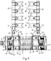
- Each cutting member 31, 32 comprises a bar 36 (Fig.s 4 and 9) fitted with a number of knives 37, each with a V-shaped cutting edge. Bars 36 are parallel to each other and supported in projecting manner on respective symmetrical supports 38 and 39.
- each support 38, 39 (Fig.4) consists of a bracket 41, 42 fitted, e.g. welded, to respective pairs of plates 43, 44.
- Plates 43 each present two openings in which are welded two sleeves 46 and 47 supporting respective linear bearings 48 and 49 (Fig.6) sliding on a pair of cylindrical guide bars 50 and 51 secured to two fixed sides 52.
- Sides 52 and guides 50 and 51 form the fixed frame of cutting device 13.
- Plates 44 also present two openings in which are welded two sleeves 53 and 54 supporting respective linear bearings 56 and 57 also sliding on guide bars 50 and 51, which are thus common to both supports 38 and 39.
- Operating mechanism 33 consists of a screw-nut screw assembly comprising a screw 58 turning on two rolling bearings 59 supported on sides 52.
- the seat of bearing 59 on one of sides 52 is closed by a flange 55, while the seat of the other bearing 59 is closed by a flange 60 with seals for sealing an extension 74 of screw 58.
- Screw 58 presents two oppositely-threaded portions 61 and 62 separated by an unthreaded portion 63. Portions 61 and 62 are engaged by respective nut screws 64 and 65 fitted to respective sleeves 66 and 67 and therefore prevented from rotating in relation to the same.
- Sleeve 66 is welded to the edges of a central opening in plates 43, and sleeve 67 to the edges of a central opening in plates 44.
- Screw 58 and guide bars 50 and 51 each present three bellows type covers 68, 69 and 71, fitted respectively between each sleeve 46, 47, 66 and respective side 52; between each sleeve 53, 54, 67 and respective side 52; and between each pair of sleeves 46-53, 47-54 and 66-67.
- Nut screws 64 and 65 are known types with planet rollers, one of which, 64, is shown in Fig.7.
- the nut screw is closed by two rings 72 fitted in rotary manner with a number of threaded planet rollers 73 engaging both respective portion 61, 62 of screw 58, and the thread of respective nut screw 64, 65.
- Each nut screw 64, 65 thus provides for moving heavy loads, even at high linear speed, over long periods of operation.
- extension 74 of screw 58 is fitted with a toothed pulley 76 driven by a toothed belt 77 (Fig.s 2 and 3) engaging a toothed drive pulley 78 fitted to the shaft of a reversible electric motor 79.
- Clockwise or anticlockwise operation of motor 79 provides for bringing together or parting cutting members 31, 32 respectively.
- Motor 79 is connected to a position transducer 81, and, by means of position and/or speed feedback, can be controlled by the aforementioned electronic control system to operate to a high degree of precision and perfectly in time with pistons 27 (Fig.1).
- the cutting device described above operates as follows.
- cutting device 13 is activated for cutting beads 12 into portions of given length.
- electric motor 79 is activated clockwise, so as to rotate pulley 76 and screw 58 clockwise via pulley 78 and toothed belt 77.
- screw 58 moves nut screws 64 and 65 towards the center together with supports 38 and 39; and bars 36 and respective knives 37 move into the Fig.5 and 6 position, so as to cut beads 12 into respective portions for supply to distributor 14 (Fig.1).
- Motor 79 is stopped by the electronic control system on the basis of the position fed back by transducer 81, after which, it is operated anticlockwise, and screw 58 parts nut screws 64 and 65 to set supports 38 and 39 to the idle position shown in Fig.4.
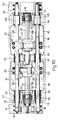
- operating mechanism 33 is located inside and supports 38 and 39 (Fig.9) substantially outside a closed housing 82, thus enabling the elimination of covers 68, 69 and 71 in Fig.6.
- Fig.s 9-14 the parts similar to those of Fig.s 4-6 are indicated using the same numbering system.
- Housing 82 (Fig.9) comprises two side walls 83, 84 and a middle wall 86 connected together by two longitudinal walls 87, 88 and an end wall 89, so as to produce two compartments 80, 85, which may be closed by a cover (not shown).
- Side walls 83 and 84 each present a rolling bearing 59 (Fig.10) on which rotates screw 58 with opposite threaded portions 61, 62 cooperating with respective nut screws 64, 65, e.g. the planet roller type shown in Fig.7.
- Middle wall 86 presents a hole 91 corresponding with the unthreaded portion 63 of screw 58.
- Each support 38, 39 (Fig.9) comprises a strong vertical lateral plate 92, 93 located to the side of side wall 83, 84 and fitted with a horizontal bracket 94 over housing 82.
- Bracket 94 is also supported on a longitudinal plate 96 outside wall 87 and integral with plate 92, 93.
- Brackets 94 are symmetrical and polygonal, and each present a portion 97 for assembling respective bars 36 of knives 37.
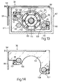
- Plate 92 (Fig.8) is substantially L-shaped, and is fitted on the ends with two jaw type appendixes 98 (Fig.11) in turn fitted with two cylindrical bars 99 sliding axially on corresponding linear bearings 100 (Fig.10) on side wall 83, and on a further two linear bearings 101 on middle wall 86.
- bars 99 are also fitted to two jaw type ends 102 (Fig.12) of a further plate 103 housed in compartment 80 of housing 82.
- Plate 103 presents a round central opening 104 in which a flange 106 of nut screw 64 is fitted by means of screws 105.
- plate 93 (Fig.14) is L-shaped, and is fitted with two jaw type appendixes 107 in turn fitted with two cylindrical bars 108 sliding axially on corresponding linear bearings 109 (Fig.10) on side wall 84, and on a further two linear bearings 110 on middle wall 86.
- bars 108 are also fitted to two jaw type ends 111 (Fig.13) of a further plate 112 housed in compartment 85 of housing 82.
- Plate 112 presents a round central opening 113 in which a flange 115 of nut screw 65 is fitted by means of screws 114.
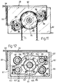
- the shorter arm of L-shaped plates 92, 93 (Fig.s 11-14) is located on the opposite side in relation to screw 58, so that bars 99 and bearings 100 and 101 (Fig.s 8, 12) are situated in two opposite corners of middle wall 86, while bars 108 and bearings 109 and 110 are situated in the other two corners of middle wall 86.
- each bearing 100 (Fig.10) on side wall 83 and each bearing 109 on side wall 84 is closed by a respective flange 116 having seals 117 on respective bar 99.
- the seats of bearings 59 of screw 58 on side walls 83 and 84 are closed by sealing flange 60 and flange 55 respectively, while extension 74 of screw 58 is fitted with toothed pulley 76 as in the previous embodiment.
- Fig.s 9-13 operates in the same way as the previous embodiment. That is, when operated in one direction, motor 79 (Fig.8) moves supports 38, 39 from the position shown by the dotted line to that shown by the continuous line in Fig.9, and vice versa if the direction of motor 79 is inverted.
- Support 38 therefore slides with the two bars 99 on bearings 100 on side wall 83 (Fig.10) and on bearings 101 on middle wall 86, while plate 103 and consequently also nut screw 64 remain inside compartment 80.
- Support 39 in turn slides with the two bars 108 on bearings 109 on side wall 84 and on bearings 110 on middle wall 86, while plate 112 and consequently also nut screw 65 remain inside compartment 85.
- the screw-nut screw pair 58, 64-65 provides for transmitting motion to supports 38, 39 in slackfree manner, while control of the rotation of screw 58 by servomotor 34 provides for troublefree adjustment of the amount of travel of supports 38, 39, and for timing said travel easily and extremely accurately with the other components of system 10 (Fig.1), in particular pistons 27 of feeder 11.
- servomotor 34 may consist of a step motor controlled by a step counter instead of position transducer 81; nut screws 64, 65 described herein may be replaced, for example, by normal or recirculating ball types; in place of belt 77, the shaft of motor 79 may be connected directly to screw 58 by means of a face coupling or precision gears, which is particularly advantageous in the case of the Fig.2-6 embodiment; and finally, the parts in housing 82 in the Fig.8-14 embodiment may be oil bath lubricated.
Landscapes
- Chemical & Material Sciences (AREA)
- Engineering & Computer Science (AREA)
- Materials Engineering (AREA)
- Organic Chemistry (AREA)
- Extrusion Moulding Of Plastics Or The Like (AREA)
- Manufacture, Treatment Of Glass Fibers (AREA)
- Processing And Handling Of Plastics And Other Materials For Molding In General (AREA)
- Transmission Devices (AREA)
- Re-Forming, After-Treatment, Cutting And Transporting Of Glass Products (AREA)
Claims (13)
- Schneidevorrichtung zum Schneiden von Extrusionsmaterial, wie beispielsweise Tropfen aus geschmolzenem Glas (12) für den Speiser (11) einer Fertigungsmaschine, mit einem Paar von sich im Wechsel betrieb bewegenden linearen Schneideelementen (31, 32) und mit Mitteln (33), um diese Mittel (31, 32) in entgegengesetzte Richtungen parallel zueinander anzutreiben , und mit einem Stellmittel (34), um die Antriebsmittel (33) so zu steuern, daß der Hub der Elemente (31, 32) einfach einstellbar und bezüglich dem Speiser (11) zeitlich abstimmbar ist, wobei das Stellmittel einen Motor (34) und einen Ortsmeßwandler (81) aufweist und die Antriebsmittel über einen beiden Elementen (31, 32) gemeinsamen Antriebsmechanismus (33) verfügen, dadurch gekennzeichnet, daß der gemeinsame Antriebsmechanismus (33) eine Schrauben-Mutter-Baueinheit aufweist und einen wechselnden, symmetrischen und synchronisierten Betrieb der Schneideelemente (31, 32) gewährleistet.
- Vorrichtung nach Anspruch 1, dadurch gekennzeichnet, daß der Mechanismus (33) eine Antriebsschraube (58) mit zwei gegenläufigen Gewindeabschnitten (61, 62) aufweist, die zugehörige Schraubenmuttern (64, 65) antreiben, die mit den beiden Elementen (31, 32) ein Ganzes bilden.
- Vorrichtung nach Anspruch 2, dadurch gekennzeichnet, daß die Schraubenmuttern (64, 65) Planetenrollen (73) aufweisen, die sogar bei schweren Lasten eine rasche Bewegung gestatten.
- Vorrichtung nach Anspruch 2 oder 3, dadurch gekennzeichnet, daß die Welle des Motors (79) mit der Schraube (58) über eine Stirnflächenkupplung oder ein mit Zähnen versehenes Antriebsmittel (76-78) verbunden ist.
- Vorrichtung nach einem der vorstehenden Ansprüche 2 bis 4, dadurch gekennzeichnet, daß beide Elemente (31, 32) eine starre Struktur (38, 39) aufweisen, die eine jeweilige Schraubenmutter (64, 65) halten, wobei die Struktur (38, 39) auf einem festen Rahmen (50-52; 82) gleitet.
- Vorrichtung nach Anspruch 5, dadurch gekennzeichnet, daß der Rahmen ein geschlossenes Gehäuse (82) aufweist, wobei jede Struktur (38, 39) gerade Führungsmittel (99, 108) aufweist, die auf linearen Lagern (100, 101; 109, 110) in dem Gehäuse (82) gleiten.
- Vorrichtung nach Anspruch 6, dadurch gekennzeichnet, daß das Gehäuse (82) ein Parallelepiped ist und zwei Seitenwände (83, 84) und eine Mittenwand (86) aufweist, die zwei Abteilungen (80, 85) bildet, wobei die Schraube (58) sich in den Seitenwänden (83, 84) dreht und jede Abteilung (80, 85) die Schraubenmutter (64, 65) von einer der Strukturen (38, 39) aufnimmt.
- Vorrichtung nach Anspruch 7, dadurch gekennzeichnet, daß das Führungsmittel wenigstens einen Stab (99, 108) aufweist, der die Schraubenmutter (64, 65) mit der Struktur (38, 39) verbindet, wobei die linearen Lager (100, 101; 109, 110) in den jeweiligen Seitenwänden (83, 84) des Gehäuses (82) und der Mittenwand (86) gehalten sind.
- Vorrichtung nach Anspruch 8, dadurch gekennzeichnet, daß das Führungsmittel zwei zylindrische Stäbe (99, 108) aufweist, die die Struktur (38, 39) mit einer Platte (106, 112) verbinden, die die Schraubenmutter (64, 65) hält und ebenfalls in einer jeweiligen Abteilung (80, 85) untergebracht ist, wobei jeder Stab (99, 108) auf einem jeweiligen Paar von linearen Lagern (100, 101; 109, 110) gleitet.
- Vorrichtung nach Anspruch 9, dadurch gekennzeichnet, daß ein Paar von Stäben (99, 108) in zwei entgegengesetzten Ecken der Mittenwand (86) angeordnet ist, wobei das andere Paar (99, 108) in den anderen beiden Ecken der Mittenwand (86) angeordnet ist.
- Vorrichtung nach einem der vorstehenden Ansprüche 6 bis 10, dadurch gekennzeichnet, daß jede Struktur über eine vertikale Platte (92, 93), die parallel zu einem der Seitenwände (83, 84) verläuft, und über einen horizontalen Träger (94) verfügt, der eine Anzahl von Messern (37) mit V-förmigen Schneidekanten hält.
- Vorrichtung nach Anspruch 5, dadurch gekennzeichnet, daß der Rahmen (50-52) zwei Seitenteile (52) aufweist, die durch ein Paar von geraden Parallelstäben (50, 51) verbunden sind, wobei sich die Schraube (58) in den Seitenteilen (52) dreht und die feste Struktur (38, 39) über ein Paar von linearen Lagern (48, 49; 56, 57) verfügt, über die sie auf dem Paar von Stäben (50, 51) geführt ist.
- Vorrichtung nach Anspruch 12, dadurch gekennzeichnet, daß der Antriebsmechanismus (33) eine Anzahl von balgartigen Abdeckungen (68, 69, 71) für die Schraube (58) und die Stäbe (50, 51) aufweist, wobei ein Satz (71) der Abdeckungen zwischen den Halterungen (38, 39) angeordnet ist und zwei weitere Sätze (68, 69) zwischen jeder Halterung (38, 39) und jedem Seitenteil (52) angeordnet sind.
Applications Claiming Priority (2)
| Application Number | Priority Date | Filing Date | Title |
|---|---|---|---|
| IT67991A IT1241595B (it) | 1990-12-11 | 1990-12-11 | Dispositivo di taglio di cordoni di materiale di estrusione, ad esempio cordoni di vetro fuso, per un alimentatore di una macchina operatrice per tale materiale |
| IT6799190 | 1990-12-11 |
Publications (2)
| Publication Number | Publication Date |
|---|---|
| EP0490294A1 EP0490294A1 (de) | 1992-06-17 |
| EP0490294B1 true EP0490294B1 (de) | 1996-06-05 |
Family
ID=11307016
Family Applications (1)
| Application Number | Title | Priority Date | Filing Date |
|---|---|---|---|
| EP91120982A Expired - Lifetime EP0490294B1 (de) | 1990-12-11 | 1991-12-06 | Vorrichtung zum Schneiden von Tropfen von Extrusionsmaterial, wie geschmolzenem Glas, für den Speiser einer Fertigungsmaschine |
Country Status (5)
| Country | Link |
|---|---|
| EP (1) | EP0490294B1 (de) |
| AT (1) | ATE138897T1 (de) |
| DE (1) | DE69120039T2 (de) |
| ES (1) | ES2087954T3 (de) |
| IT (1) | IT1241595B (de) |
Families Citing this family (7)
| Publication number | Priority date | Publication date | Assignee | Title |
|---|---|---|---|---|
| DE4222310A1 (de) * | 1992-07-08 | 1994-01-13 | Gps Glasprod Serv Gmbh | Vorrichtung zur Auftrennung eines oder mehrerer Stränge schmelzflüssigen Glases in einzelne Glasposten |
| IT1267152B1 (it) * | 1994-11-18 | 1997-01-28 | Bottero Spa | Gruppo di taglio, particolarmente per la formatura di gocce di vetro. |
| IT1294870B1 (it) * | 1997-09-17 | 1999-04-23 | Bdf Boscato & Dalla Fontana Sp | Dispositivo per il taglio di gocce di vetro fuso in uscita da un alimentatore di una macchina per la produzione di articoli di vetro. |
| ITTO20070309A1 (it) | 2007-05-07 | 2008-11-08 | Bottero Spa | Dispositivo di tenuta e attuatore lineare per un gruppo forbici per una macchina di formatura di articoli di vetro cavo provvisto di tale dispositivo di tenuta |
| US9855578B2 (en) | 2013-12-12 | 2018-01-02 | Palo Alto Research Center Incorporated | Co-extrusion print head with edge bead reduction |
| DE102014013980A1 (de) * | 2014-09-19 | 2016-03-24 | Gps Glasproduktions-Service Gmbh | Feedervorrichtung einer Glasmaschine |
| US9755221B2 (en) | 2015-06-26 | 2017-09-05 | Palo Alto Research Center Incorporated | Co-extruded conformal battery separator and electrode |
Family Cites Families (3)
| Publication number | Priority date | Publication date | Assignee | Title |
|---|---|---|---|---|
| US4444079A (en) * | 1982-06-14 | 1984-04-24 | Maul Technology Corporation | Profile control for shear mechanism |
| GB8412249D0 (en) * | 1984-05-14 | 1984-06-20 | Bhf Eng Ltd | Straight-line shearing |
| US4699643A (en) * | 1985-05-07 | 1987-10-13 | Emhart Industries, Inc. | Straight line shear |
-
1990
- 1990-12-11 IT IT67991A patent/IT1241595B/it active IP Right Grant
-
1991
- 1991-12-06 DE DE69120039T patent/DE69120039T2/de not_active Expired - Lifetime
- 1991-12-06 EP EP91120982A patent/EP0490294B1/de not_active Expired - Lifetime
- 1991-12-06 AT AT91120982T patent/ATE138897T1/de active
- 1991-12-06 ES ES91120982T patent/ES2087954T3/es not_active Expired - Lifetime
Also Published As
| Publication number | Publication date |
|---|---|
| IT1241595B (it) | 1994-01-19 |
| ATE138897T1 (de) | 1996-06-15 |
| DE69120039T2 (de) | 1996-10-02 |
| ES2087954T3 (es) | 1996-08-01 |
| IT9067991A0 (it) | 1990-12-11 |
| EP0490294A1 (de) | 1992-06-17 |
| IT9067991A1 (it) | 1992-06-12 |
| DE69120039D1 (de) | 1996-07-11 |
Similar Documents
| Publication | Publication Date | Title |
|---|---|---|
| EP0490294B1 (de) | Vorrichtung zum Schneiden von Tropfen von Extrusionsmaterial, wie geschmolzenem Glas, für den Speiser einer Fertigungsmaschine | |
| CN109592426B (zh) | 动力电池顶盖板上料机构 | |
| US4903460A (en) | Device for varying the opening between the welding element and the counter-welding element in packaging machines | |
| KR200485332Y1 (ko) | 스프링 성형기용 서보 회전형 풀 기능 커터 조립체 | |
| JP2006168823A (ja) | 横型製袋充填機におけるエンドシール装置 | |
| CN206886118U (zh) | 一种翻转机构 | |
| CN221163676U (zh) | 一种纸盒链自动调整宽度结构 | |
| EP0712812B1 (de) | Schneidevorrichtung, insbesondere für geschmolzene Glastropfen | |
| CN213677440U (zh) | 一种纸箱输送装置 | |
| CN113619198B (zh) | 一种联动除泡装置及盒体生产设备 | |
| KR20090027335A (ko) | 반도체패키지의 프레스 자재 이송장치 | |
| CN209455169U (zh) | 一种伺服驱动式多功能装盒机 | |
| CN221133745U (zh) | 一种带有定位结构的冲孔装置 | |
| CN223031425U (zh) | 一种包装机用放膜机构及包装机 | |
| JP2006312470A (ja) | 横型製袋充填機におけるエンドシール装置 | |
| US3485010A (en) | Device for driving package-forming jaws of a packing machine | |
| CN220517403U (zh) | 一种注塑机的传输机构 | |
| CN216710546U (zh) | 输送供料装置 | |
| EP1630112A1 (de) | Abstreifersystem für Hohlglasmaschinen | |
| CN220744822U (zh) | 一种布料输送装置 | |
| CN224061866U (zh) | 一种运载小车自动校准结构 | |
| CN222877095U (zh) | 一种用于夹持馄饨的间距可调夹爪 | |
| CN114132785B (zh) | 一种压辊松紧调节系统 | |
| CN223733982U (zh) | 一种钢带纵剪加工用送料装置 | |
| CN213011883U (zh) | 一种追踪式真空旋盖机 |
Legal Events
| Date | Code | Title | Description |
|---|---|---|---|
| PUAI | Public reference made under article 153(3) epc to a published international application that has entered the european phase |
Free format text: ORIGINAL CODE: 0009012 |
|
| AK | Designated contracting states |
Kind code of ref document: A1 Designated state(s): AT BE CH DE ES FR GB LI NL SE |
|
| 17P | Request for examination filed |
Effective date: 19921102 |
|
| 17Q | First examination report despatched |
Effective date: 19941201 |
|
| GRAH | Despatch of communication of intention to grant a patent |
Free format text: ORIGINAL CODE: EPIDOS IGRA |
|
| GRAA | (expected) grant |
Free format text: ORIGINAL CODE: 0009210 |
|
| AK | Designated contracting states |
Kind code of ref document: B1 Designated state(s): AT BE CH DE ES FR GB LI NL SE |
|
| REF | Corresponds to: |
Ref document number: 138897 Country of ref document: AT Date of ref document: 19960615 Kind code of ref document: T |
|
| REG | Reference to a national code |
Ref country code: ES Ref legal event code: BA2A Ref document number: 2087954 Country of ref document: ES Kind code of ref document: T3 |
|
| REF | Corresponds to: |
Ref document number: 69120039 Country of ref document: DE Date of ref document: 19960711 |
|
| REG | Reference to a national code |
Ref country code: CH Ref legal event code: NV Representative=s name: BOVARD AG PATENTANWAELTE |
|
| ET | Fr: translation filed | ||
| REG | Reference to a national code |
Ref country code: ES Ref legal event code: FG2A Ref document number: 2087954 Country of ref document: ES Kind code of ref document: T3 |
|
| PG25 | Lapsed in a contracting state [announced via postgrant information from national office to epo] |
Ref country code: SE Effective date: 19960905 |
|
| PG25 | Lapsed in a contracting state [announced via postgrant information from national office to epo] |
Ref country code: AT Effective date: 19961206 |
|
| PG25 | Lapsed in a contracting state [announced via postgrant information from national office to epo] |
Ref country code: LI Effective date: 19961231 Ref country code: CH Effective date: 19961231 Ref country code: BE Effective date: 19961231 |
|
| PLBE | No opposition filed within time limit |
Free format text: ORIGINAL CODE: 0009261 |
|
| STAA | Information on the status of an ep patent application or granted ep patent |
Free format text: STATUS: NO OPPOSITION FILED WITHIN TIME LIMIT |
|
| 26N | No opposition filed | ||
| BERE | Be: lapsed |
Owner name: BOTTERO S.P.A. Effective date: 19961231 |
|
| PG25 | Lapsed in a contracting state [announced via postgrant information from national office to epo] |
Ref country code: NL Effective date: 19970701 |
|
| REG | Reference to a national code |
Ref country code: CH Ref legal event code: PL |
|
| NLV4 | Nl: lapsed or anulled due to non-payment of the annual fee |
Effective date: 19970701 |
|
| REG | Reference to a national code |
Ref country code: GB Ref legal event code: IF02 |
|
| PGFP | Annual fee paid to national office [announced via postgrant information from national office to epo] |
Ref country code: ES Payment date: 20091203 Year of fee payment: 19 |
|
| PGFP | Annual fee paid to national office [announced via postgrant information from national office to epo] |
Ref country code: GB Payment date: 20091125 Year of fee payment: 19 |
|
| PGFP | Annual fee paid to national office [announced via postgrant information from national office to epo] |
Ref country code: FR Payment date: 20100115 Year of fee payment: 19 |
|
| PGFP | Annual fee paid to national office [announced via postgrant information from national office to epo] |
Ref country code: DE Payment date: 20091204 Year of fee payment: 19 |
|
| GBPC | Gb: european patent ceased through non-payment of renewal fee |
Effective date: 20101206 |
|
| REG | Reference to a national code |
Ref country code: FR Ref legal event code: ST Effective date: 20110831 |
|
| PG25 | Lapsed in a contracting state [announced via postgrant information from national office to epo] |
Ref country code: FR Free format text: LAPSE BECAUSE OF NON-PAYMENT OF DUE FEES Effective date: 20110103 |
|
| REG | Reference to a national code |
Ref country code: DE Ref legal event code: R119 Ref document number: 69120039 Country of ref document: DE Effective date: 20110701 |
|
| PG25 | Lapsed in a contracting state [announced via postgrant information from national office to epo] |
Ref country code: DE Free format text: LAPSE BECAUSE OF NON-PAYMENT OF DUE FEES Effective date: 20110701 Ref country code: GB Free format text: LAPSE BECAUSE OF NON-PAYMENT OF DUE FEES Effective date: 20101206 |
|
| REG | Reference to a national code |
Ref country code: ES Ref legal event code: FD2A Effective date: 20120206 |
|
| PG25 | Lapsed in a contracting state [announced via postgrant information from national office to epo] |
Ref country code: ES Free format text: LAPSE BECAUSE OF NON-PAYMENT OF DUE FEES Effective date: 20101207 |