EP0490213B1 - Noise and vibration damping device for vehicle opening exposed to a tangential air flow, especially for sliding roofs - Google Patents
Noise and vibration damping device for vehicle opening exposed to a tangential air flow, especially for sliding roofs Download PDFInfo
- Publication number
- EP0490213B1 EP0490213B1 EP19910120683 EP91120683A EP0490213B1 EP 0490213 B1 EP0490213 B1 EP 0490213B1 EP 19910120683 EP19910120683 EP 19910120683 EP 91120683 A EP91120683 A EP 91120683A EP 0490213 B1 EP0490213 B1 EP 0490213B1
- Authority
- EP
- European Patent Office
- Prior art keywords
- wind deflector
- air
- net
- opening
- edge
- Prior art date
- Legal status (The legal status is an assumption and is not a legal conclusion. Google has not performed a legal analysis and makes no representation as to the accuracy of the status listed.)
- Expired - Lifetime
Links
Images

Classifications
-
- B—PERFORMING OPERATIONS; TRANSPORTING
- B60—VEHICLES IN GENERAL
- B60J—WINDOWS, WINDSCREENS, NON-FIXED ROOFS, DOORS, OR SIMILAR DEVICES FOR VEHICLES; REMOVABLE EXTERNAL PROTECTIVE COVERINGS SPECIALLY ADAPTED FOR VEHICLES
- B60J7/00—Non-fixed roofs; Roofs with movable panels, e.g. rotary sunroofs
- B60J7/22—Wind deflectors for open roofs
Definitions
- the invention relates to a device for noise and vibration reduction at tangentially overflow openings of a sunroof of motor vehicles according to the preamble of claim 1.
- the invention has for its object to provide a device for noise and vibration reduction in motor vehicle openings, if possible, no additional Space is required, has a good effectiveness and hardly affects the aesthetics.
- the wind deflector is provided with an air-permeable network at least in some areas of its surface.
- the wind deflector has corresponding openings which are then filled by the net.
- it could also be a metallic grid which is connected in a suitable manner to the wind deflector.
- the net or grille can be attached to the wind deflector with the prepared openings.
- the net or grid could also be injected during the wind deflector spraying process.
- the wind deflector designed according to the invention essentially fulfills two functions: on the one hand, it partially deflects the air flowing against the wind deflector from the front upward, like a conventional wind deflector.
- the air flow breaks off at the rear edge of the wind deflector. This creates vortices, which are already reduced compared to the vortices generated by full-size wind deflectors.
- a certain proportion of the incoming air also flows through the areas of the wind deflector which are provided with the air-permeable net or grille.
- the partial flow of air that has passed through the network is formed as a very fine turbulent layer, the one below the first turbulent first air flow flows out at the back.
- the finely turbulent second layer behind the net or grid forms an additionally created boundary layer or shear layer, which acts as a "cushion" for the turbulent layer above it, which is caused by the stall at the wind deflector edge.
- the extremely turbulent lower partial flow reduces the otherwise possible build-up of the extremely disturbing pressure pulsations known for the excitation of the so-called sunroof boom.
- the phenomenon of booming which is often observed when the sunroof is open, hardly occurs any more, in which the interior of the vehicle, in conjunction with the overflowed sunroof opening, acts like a Helmholtz resonator.
- the dead water area directly behind the wind deflector that arises with conventional wind deflectors does not arise with the wind deflector according to the invention, because this area is constantly filled up with the extremely turbulent flow. This also reduces the stall at the free wind deflector edge. In addition to reducing the buzzing noises already described, the noise that can be perceived as a broadband flow noise can also be significantly reduced.
- the part of the air flow that strikes the edge of the opening is much more uniform.
- the subjective sensation of train of the vehicle occupants sitting in the area of the sunroof opening is considerably more pleasant than under the influence of the violent pulsation vibrations with local and periodic high air speeds.
- the resistance of the used network, the structure of the network carrier holding the network, its angle of attack and height have a decisive influence on the achievable result.
- good coordination can be achieved with regard to the sometimes contradicting goals, such as drafts, noise or booming.
- the measures according to the invention do not require any additional weight and can also be implemented at a relatively low cost.
- Fig. 1 of the drawing the roof 1 of a passenger car is shown, which has a comparatively large opening 2.
- the opening 2 can be closed by two lids, a front lid 3 and a rear lid 4.
- the measures explained below can also be applied to a conventional sunroof with only a single lid.
- a wind deflector 7 protruding from the vehicle contour outwards or obliquely backwards is provided transversely to the air flow 5 and parallel to the front edge 6 of the opening 2.
- the wind deflector 7 does not have a completely closed surface, but is provided with an air-permeable net 8 or grid, at least in parts of its surface. In this way, at least in these partial areas of its surface, the wind deflector is permeable to a certain extent.
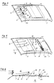
- FIG. 3a shows a wind deflector 9 which has a number of openings 10 arranged next to one another.
- the wind deflector 9 forms a carrier for the circular openings 10, the passage cross section of which is filled with the net 8.
- the wind deflector 11 can also comprise an outer peripheral frame 12 on which the net 8 is fixed.
- the wind deflector 7 according to FIGS. 1 and 3c likewise comprises a peripheral frame 12, which, however, additionally has intermediate webs 13 running perpendicular to its long sides.
- the wind deflector 14, shown schematically in FIG. 3d, has an approximately part-circular contour in side view and the free edge 15 points towards the rear.
- the wind deflector 16 according to FIG. 3e is also provided with the net 8 almost over the entire surface and has a cross section the shape of a flat S.
- the free edge 17 is directed towards the rear.
- the mode of operation of the wind deflector according to FIGS. 1 and 2 or 3c is as follows:
- the flow S arriving via the front edge of the roof is deflected upwards in part as a partial flow S1, as in a conventional wind deflector.
- This partial flow S1 breaks off at the rear edge of the wind deflector 7. Since only the partial flow S1 flows over the wind deflector 7, the turbulent air layer which then forms already has comparatively smaller vortices 18.
- a part of the flow S coming towards the wind deflector can also flow through the wind deflector 7 as a partial flow S2 because of the network 8.
- Behind the wind deflector there is not the otherwise usual dead water area, but a very fine turbulent flow with very small vortices 19.
- An air layer essentially consisting of the partial flow S2 builds up between the turbulent flow S1 flowing at flow speed and the air mass R resting in the vehicle interior on.
- the layer of the partial flow S2 now largely prevents the otherwise observed build-up of the pressure pulsations responsible for the excitation of the boom frequencies.
- the flow noise which is generally unavoidable with wind deflectors, and the subjective draft sensation mentioned above are noticeably improved.
- the principle of the partially flowed air guiding element can also be used in a wind deflector 20 shown in FIG. 4, which is provided with additional air guiding elements 21 (similar to flaps) projecting beyond its rear edge. If such air guiding elements 21 are provided with the net 8 or grid over a large area of their surface, then the highly turbulent otherwise generated after the wind deflector 20 can also be used here Influence the flow layer in such a way that the periodic pulsation vibrations (Wummmern) are markedly reduced. In addition, the otherwise significant flow noise is also reduced or shifted to a frequency range that is perceived as more pleasant.
- the wind deflectors or air-directing elements provided with the flow-through network 8 have been arranged throughout on the front edge 6 of the opening 2.
- Good results with regard to noise and vibration reduction can also be achieved with a wind deflector 22 according to FIG. 5, which is arranged in front of the downstream rear edge 23 of the opening 2.
- FIG. 6 Its mode of operation is also described with the aid of FIG. 6 with the aid of a double sliding roof that has a front cover 3 and a rear cover 4.
- the front cover 3 is slightly raised and the rear cover 4 is pushed forward.
- the wind deflector 22 arranged on the rear edge 23 could also be used in the same way on a sliding roof opening with only one cover.
- the wind deflector 22 can also lie at a greater distance from the edge 23 if, due to the aerodynamic conditions, the air flow further forward again towards the opening 2 is directed below.
- the wind deflectors 7 or 11 arranged at the front of the opening 2 also give clear advantages if a roof rack is arranged above the opening 2 of the sunroof.
- a roof rack is arranged above the opening 2 of the sunroof.
- the strong air vortices after the stall come into contact with the crossbar of the roof rack, which is stimulated to vibrate. These vibrations are largely introduced as structure-borne noise into the bodywork via the roof rack feet, and partly also directly as airborne sound through the opening 2 into the vehicle interior.
Description
Die Erfindung bezieht sich auf eine Vorrichtung zur Geräusch- und Schwingungsminderung an tangential überströmten Öffnungen eines Schiebedachs von Kraftfahrzeugen nach dem Oberbegriff des Patentanspruchs 1.The invention relates to a device for noise and vibration reduction at tangentially overflow openings of a sunroof of motor vehicles according to the preamble of
Derartige Vorrichtungen sind bereits bekannt (DE-A- 38 42 676), wobei am hinteren Rand des Windabweisers ein über diesen Rand hinaus nach oben schwenkbares zusätzliches Luftleitelement vorgesehen ist. Das Luftleitelement teilt die am Rand des Windabweisers abreißende Strömung zusätzlich auf und bildet einen Störkörper. Die Wirkungsweise derartiger zusätzlicher Luftleitelemente (Flaps) ist je nach Karosserieform unterschiedlich. Die Flaps erfordern darüber hinaus zusätzlichen Bauraum und stören auch den ästhetischen Gesamteindruck in gewissem Maße.Devices of this type are already known (DE-A-38 42 676), an additional air guiding element which can be pivoted upward beyond this edge being provided on the rear edge of the wind deflector. The air guiding element also divides the flow breaking off at the edge of the wind deflector and forms an interference body. The mode of operation of such additional air guiding elements (flaps) differs depending on the body shape. The flaps also require additional installation space and also disturb the overall aesthetic impression to a certain extent.
Der Erfindung liegt die Aufgabe zugrunde, eine Vorrichtung zur Geräusch- und Schwingungsminderung an Kraftfahrzeug-Öffnungen zu schaffen, die möglichst keinen zusätzlichen Bauraum benötigt, eine gute Wirksamkeit hat und auch die Ästhetik kaum beeinträchtigt.The invention has for its object to provide a device for noise and vibration reduction in motor vehicle openings, if possible, no additional Space is required, has a good effectiveness and hardly affects the aesthetics.
Diese Aufgabe wird erfindungsgemäß dadurch gelöst, daß der Windabweiser zumindest in Teilbereichen seiner Fläche mit einem luftdurchlässigen Netz versehen ist. In den Flächenbereichen, in denen das Netz angeordnet ist, hat der Windabweiser entsprechende Öffnungen, die dann von dem Netz ausgefüllt werden. Es könnte aber auch ein metallisches Gitter sein, das in geeigneter Weise mit dem Windabweiser verbunden ist. In beiden Fällen kann das Netz bzw. das Gitter nachträglich an dem mit den vorbereiteten Öffnungen versehenen Windabweiser befestigt werden. Das Netz bzw. Gitter könnte aber auch beim Spritzvorgang des Windabweisers miteingespritzt werden. Schließlich ist es auch denkbar, das Netz in einem Arbeitsgang beim Spritzen oder Spritzgießen des Windabweisers mitzufertigen.This object is achieved in that the wind deflector is provided with an air-permeable network at least in some areas of its surface. In the surface areas in which the net is arranged, the wind deflector has corresponding openings which are then filled by the net. However, it could also be a metallic grid which is connected in a suitable manner to the wind deflector. In both cases, the net or grille can be attached to the wind deflector with the prepared openings. The net or grid could also be injected during the wind deflector spraying process. Finally, it is also conceivable to manufacture the net in one operation when spraying or injection molding the wind deflector.
Weitere vorteilhafte Einzelheiten der Erfindung sind in den Unteransprüchen gekennzeichnet.Further advantageous details of the invention are characterized in the subclaims.
Der erfindungsgemäß ausgebildete Windabweiser erfüllt im wesentlichen zwei Funktionen: Zum einen lenkt er die von vorne quer gegen den Windabweiser anströmende Luft teilweise - wie ein herkömmlicher Windabweiser - nach oben ab. Dabei reißt die Luftströmung an der hinteren Kante des Windabweisers ab. Es bilden sich dadurch Wirbel aus, die aber gegenüber den von vollflächigen Windabweisern erzeugten Wirbeln schon reduziert sind. Zum anderen durchströmt ein gewisser Anteil der anströmenden Luft aber auch die Bereiche des Windabweisers, die mit dem luftdurchlässigen Netz oder Gitter versehen sind. Der Teilstrom der Luft, der das Netz passiert hat, bildet sich als sehr fein turbulente Schicht aus, die unterhalb der zuerstgenannten turbulenten ersten Luftströmung nach hinten abströmt. Die fein turbulente zweite Schicht hinter dem Netz bzw. Gitter bildet eine zusätzlich geschaffene Grenzschicht bzw. Scherschicht, die als "Polster" für die darüber befindliche turbulente Schicht wirkt, die durch den an der Windabweiserkante verursachten Strömungsabriß verursacht ist.The wind deflector designed according to the invention essentially fulfills two functions: on the one hand, it partially deflects the air flowing against the wind deflector from the front upward, like a conventional wind deflector. The air flow breaks off at the rear edge of the wind deflector. This creates vortices, which are already reduced compared to the vortices generated by full-size wind deflectors. On the other hand, a certain proportion of the incoming air also flows through the areas of the wind deflector which are provided with the air-permeable net or grille. The partial flow of air that has passed through the network is formed as a very fine turbulent layer, the one below the first turbulent first air flow flows out at the back. The finely turbulent second layer behind the net or grid forms an additionally created boundary layer or shear layer, which acts as a "cushion" for the turbulent layer above it, which is caused by the stall at the wind deflector edge.
Die feinst turbulente untere Teilströmung vermindert den sonst möglichen Aufbau der für die Anregung der als sogenanntes Schiebedach-Wummern bekannten und äußerst störenden Druckpulsationen. Es kommt kaum mehr zu der bei geöffnetem Schiebedach häufig beobachteten Erscheinung des Wummerns, bei dem der Fahrzeuginnenraum in Verbindung mit der überströmten Schiebedachöffnung wie ein Helmholtz-Resonator wirkt.The extremely turbulent lower partial flow reduces the otherwise possible build-up of the extremely disturbing pressure pulsations known for the excitation of the so-called sunroof boom. The phenomenon of booming, which is often observed when the sunroof is open, hardly occurs any more, in which the interior of the vehicle, in conjunction with the overflowed sunroof opening, acts like a Helmholtz resonator.
Das mit konventionellen Windabweisern entstehende Totwassergebiet direkt hinter dem Windabweiser entsteht mit dem erfindungsgemäßen Windabweiser nicht, denn dieses Gebiet wird mit der feinst turbulenten Strömung stetig aufgefüllt. Dadurch wird auch der Strömungsabriß an der freien Windabweiserkante geringer. Außer dem Abbau der schon beschriebenen Wummergeräusche läßt sich auch das als breitbandiges Strömungsgeräusch wahrnehmbare Rauschen deutlich herabsetzen.The dead water area directly behind the wind deflector that arises with conventional wind deflectors does not arise with the wind deflector according to the invention, because this area is constantly filled up with the extremely turbulent flow. This also reduces the stall at the free wind deflector edge. In addition to reducing the buzzing noises already described, the noise that can be perceived as a broadband flow noise can also be significantly reduced.
Weiterhin ist der Teil der Luftströmung, der auf den Rand der Öffnung auftrifft, wesentlich gleichmäßiger. Demzufolge ist das subjektive Zugempfinden der im Bereich der Schiebedachöffnung sitzenden Fahrzeuginsassen wesentlich angenehmer als unter dem Einfluß der heftigen Pulsationsschwingungen mit örtlichen und periodischen hohen Luftgeschwindigkeiten.Furthermore, the part of the air flow that strikes the edge of the opening is much more uniform. As a result, the subjective sensation of train of the vehicle occupants sitting in the area of the sunroof opening is considerably more pleasant than under the influence of the violent pulsation vibrations with local and periodic high air speeds.
Selbstverständlich haben auf die Wirkungsweise des neuen Windabweisers beispielsweise die Widerstandszahl des verwendeten Netzes, der Aufbau des das Netz haltenden Netzträgers, dessen Anstellwinkel und Höhe entscheidenden Einfluß auf das erreichbare Ergebnis. Es lassen sich jedoch gute Abstimmungen im Hinblick auf die sich zum Teil widersprechenden Ziele, wie Zugerscheinungen, Rauschen oder Wummern, erreichen. Die erfindungsgemäßen Maßnahmen bedingen kein zusätzliches Gewicht und sind auch unter einem relativ geringen Kostenaufwand realisierbar.Of course, the resistance of the used network, the structure of the network carrier holding the network, its angle of attack and height have a decisive influence on the achievable result. However, good coordination can be achieved with regard to the sometimes contradicting goals, such as drafts, noise or booming. The measures according to the invention do not require any additional weight and can also be implemented at a relatively low cost.
Die Erfindung ist im folgenden anhand mehrerer in der Zeichnung dargestellter Ausführungsbeispiele näher erläutert. Es zeigt
- Fig. 1
- eine perspektivische Ansicht auf ein Fahrzeugdach mit einem ersten Ausführungsbeispiel der erfindungsgemäßen Vorrichtung;
- Fig. 2
- einen schematisierten Schnitt nach der Linie II-II in Fig. 1;
- Fig. 3
- verschiedene Frontansichten weiterer Ausführungsbeispiele, stark schematisiert mit zugeordneten Querschnitten;
- Fig. 4
- eine der Fig. 1 entsprechende Ansicht eines weiteren Ausführungsbeispiels;
- Fig. 5
- eine der Fig. 1 entsprechende Ansicht eines nochmals abgeänderten Ausführungsbeispiels und
- Fig. 6
- einen schematisierten Schnitt nach der Linie VI-VI in Fig. 5.
- Fig. 1
- a perspective view of a vehicle roof with a first embodiment of the device according to the invention;
- Fig. 2
- a schematic section along the line II-II in Fig. 1;
- Fig. 3
- different front views of further exemplary embodiments, highly schematic with assigned cross sections;
- Fig. 4
- a view corresponding to Figure 1 of another embodiment.
- Fig. 5
- a view corresponding to FIG. 1 of a further modified embodiment and
- Fig. 6
- a schematic section along the line VI-VI in Fig. 5th
In Fig. 1 der Zeichnung ist das Dach 1 eines Personenkraftwagens dargestellt, das eine vergleichsweise große Öffnung 2 hat. Die Öffnung 2 ist durch zwei Deckel verschließbar, einen vorderen Deckel 3 und einen hinteren Deckel 4. Die nachfolgend erläuterten Maßnahmen können aber ebenfalls an einem üblichen Schiebedach mit nur einem einzigen Deckel angewendet werden.In Fig. 1 of the drawing, the
Quer zur Luftströmung 5 und parallel zum vorderen Rand 6 der Öffnung 2 ist ein von der Fahrzeugkontur nach außen bzw. schräg nach hinten oben abstehender Windabweiser 7 vorgesehen. Der Windabweiser 7 hat keine vollkommen geschlossene Fläche, sondern ist zumindest in Teilbereichen seiner Fläche mit einem luftdurchlässigen Netz 8 bzw. Gitter versehen. Zumindest in diesen Teilbereichen seiner Fläche ist auf diese Weise der Windabweiser in einem gewissen Ausmaß strömungsdurchlässig. Wie man aus Fig. 3 erkennt, sind für die Ausbildung eines Windabweisers dabei verschiedene Varianten möglich. Fig. 3a zeigt einen Windabweiser 9, der eine Reihe von nebeneinander geordneten Öffnungen 10 hat. Der Windabweiser 9 bildet dabei gewissermaßen einen Träger für die kreisrunden Öffnungen 10, deren Durchtrittsquerschnitt mit dem Netz 8 ausgefüllt ist. Gemäß Fig. 3b kann der Windabweiser 11 aber auch einen äußeren umlaufenden Rahmen 12 umfassen, an dem das Netz 8 festgelegt ist. Der Windabweiser 7 gemäß Fig. 1 und Fig. 3c umfaßt ebenfalls einen umlaufenden Rahmen 12, der aber zusätzlich noch senkrecht zu seinen Längsseiten verlaufende Zwischenstege 13 hat.A
Der in Fig. 3d schematisch dargestellte Windabweiser 14 hat in Seitenansicht eine etwa teilkreisförmige Kontur und der freie Rand 15 weist dabei nach hinten. Der Windabweiser 16 gemäß Fig. 3e ist ebenfalls nahezu vollflächig mit dem Netz 8 versehen und hat im Querschnitt die Form eines flachen S. Auch hier ist der freie Rand 17 nach hinten gerichtet.The
Die Wirkungsweise des Windabweisers nach den Fig. 1 und 2 bzw. 3c ist folgende: Die über die Vorderkante des Daches ankommende Strömung S wird zum Teil als Teilstrom S1 nach oben abgelenkt wie bei einem herkömmlichen Windabweiser. Diese Teilströmung S1 reißt an der hinteren Kante des Windabweisers 7 ab. Da nur der Teilstrom S1 den Windabweiser 7 überströmt, weist die sich danach ausbildende turbulente Luftschicht schon vergleichsweise geringere Wirbel 18 auf. Ein Teil der auf den Windabweiser zukommenden Strömung S kann wegen des Netzes 8 aber auch den Windabweiser 7 als Teilstrom S2 durchströmen. Es entsteht hinter dem Windabweiser nicht das sonst übliche Totwassergebiet, sondern eine sehr fein turbulente Strömung mit sehr kleinen Wirbeln 19. Es baut sich eine im wesentlichen aus dem Teilstrom S2 bestehende Luftschicht zwischen der mit Strömungsgeschwindigkeit fließenden turbulenten Strömung S1 und der im Fahrzeuginnenraum ruhenden Luftmasse R auf. Die Schicht der Teilströmung S2 verhindert nun weitgehend den sonst beobachteten Aufbau der für die Anregung der Wummerfrequenzen verantwortlichen Druckpulsationen. Gleichzeitig sind aber auch das mit Windabweisern generell nicht zu vermeidende Strömungsrauschen und das schon weiter oben erwähnte subjektive Zugempfinden spürbar verbessert.The mode of operation of the wind deflector according to FIGS. 1 and 2 or 3c is as follows: The flow S arriving via the front edge of the roof is deflected upwards in part as a partial flow S1, as in a conventional wind deflector. This partial flow S1 breaks off at the rear edge of the
Das Prinzip des teilweise durchströmten Luftleitelementes läßt sich auch bei einem in Fig. 4 dargestellten Windabweiser 20 nutzen, der mit zusätzlichen über seinen hinteren Rand wegragenden Luftleitelementen 21 (ähnlich Flaps) versehen ist. Versieht man derartige Luftleitelemente 21 über einen großen Bereich ihrer Fläche mit dem Netz 8 bzw. Gitter, so läßt sich auch hier die nach dem Windabweiser 20 sonst erzeugte stark turbulente Strömungsschicht so beeinflussen, daß die periodischen Pulsationsschwingungen (Wummmern) markant vermindert sind. Zusätzlich ist aber dabei das sonst erhebliche Strömungsrauschen ebenfalls reduziert bzw. in einen als angenehmer empfundenen Frequenzbereich verlagert.The principle of the partially flowed air guiding element can also be used in a
Bei den bisher beschriebenen Ausführungsbeispielen sind die mit dem durchströmbaren Netz 8 versehenen Windabweiser bzw. Luftleitelemente durchwegs am vorderen Rand 6 der Öffnung 2 angeordnet gewesen. Gute Ergebnisse hinsichtlich der Geräusch- und Schwingungsreduzierung sind aber auch mit einem Windabweiser 22 gemäß Fig. 5 erreichbar, der vor dem stromabwärts liegenden hinteren Rand 23 der Öffnung 2 angeordnet ist. Seine Wirkungsweise wird anhand von Fig. 6 ebenfalls mit Hilfe eines Doppelschiebe-Hebedaches beschrieben, das einen vorderen Deckel 3 und einen hinteren Deckel 4 hat. Wie man erkennt, ist der vordere Deckel 3 etwas angehoben und der hintere Deckel 4 nach vorne geschoben. Natürlich könnte der am hinteren Rand 23 angeordnete Windabweiser 22 auch an einer Schiebedachöffnung mit lediglich einem Deckel in der gleichen Weise verwendet werden.In the exemplary embodiments described so far, the wind deflectors or air-directing elements provided with the flow-through
Die parallel über den vorderen Rand des Daches 1 ankommende Strömung S wird durch den vorderen Deckel 3 etwas nach oben abgelenkt. Am hinteren Rand des Deckels 3 reißt die Luftströmung ab und es werden wiederum kräftige Wirbel 18 erzeugt. Wegen des vor dem hinteren Rand 23 der Öffnung 2 angeordneten Windabweisers 22 treffen diese Wirbel 18 jedoch nicht mehr auf den hinteren Rand 23 der Öffnung 2. Die mit den Wirbeln 18 behaftete Strömung trifft auf den Windabweiser 22 und durchströmt dessen Netz 8. Hinter dem Netz 8 bildet sich eine sehr stark vergleichmäßigte, allenfalls noch ganz fein turbulente Luftströmung aus. Das sonst hinzunehmende Strömungsrauschen ist stark reduziert. Aber auch die Anregung der ruhenden Luftmasse R im Fahrzeuginnenraum wie bei einem Helmholtz-Resonator wird vermindert.The flow S arriving in parallel over the front edge of the
Abweichend von dem der Zeichnung entnehmbaren Ort des Windabweisers 22 relativ nahe vor dem hinteren Rand 23 der Öffnung 2 kann der Windabweiser 22 auch mit einem größeren Abstand vor dem Rand 23 liegen, wenn aufgrund der aerodynamischen Gegebenheiten die Luftströmung weiter vorne wieder gegen die Öffnung 2 nach unten gerichtet ist.Deviating from the location of the
Es hat sich schließlich auch gezeigt, daß die vorne an der Öffnung 2 angeordneten Windabweiser 7 oder 11 auch deutliche Vorteile ergeben, wenn über der Öffnung 2 des Schiebedaches ein Dachträger angeordnet ist. Mit herkömmlichen Windabweisern treffen die nach dem Strömungsabriß starken Luftwirbel auf den Querholm des Dachträgers, der zu Schwingungen angeregt wird. Diese Schwingungen werden zu einem großen Teil als Körperschall über die Dachträgerfüße in den Karosseriekörper eingeleitet, zum Teil auch direkt als Luftschall über die Öffnung 2 in den Fahrzeuginnenraum.Finally, it has also been shown that the
Mit den erfindungsgemäß mit einem Netz 8 oder Gitter versehenen Windabweisern wird nicht so viel Luft nach oben abgelenkt, die auch nicht so weit nach oben abgedrängt wird. Die dennoch erzeugten Wirbel 18 sind weniger turbulent und treffen sanfter und gleichmäßiger auf den Träger-Querholm, so daß eine merkliche akustische Komfortverbesserung erreichbar ist.With the wind deflectors provided according to the invention with a net 8 or grille, not as much air is deflected upwards, which is also not pushed as far upwards. The
Claims (9)
- A device for reducing noise and vibration at an opening (2) exposed to a tangential air flow in a sliding roof for a vehicle, the device comprising a wind deflector (7) which extends transversely to the direction of flow and parallel to an edge of the opening (2) and projects outwards from the vehicle contour, characterised in that the wind deflector (7, 9, 11, 14, 16) has an air-permeable net or grille (8) over at least part of its surface.
- A device according to claim 1 comprising side-by- side openings (10) in the wind deflector (9), characterised in that the net (8) is disposed in or on the openings (10).
- A device according to claim 1, characterised in that the wind deflector (11) has an external peripheral frame (12) to which the net (8) is fastened.
- A device according to claim 3, characterised in that the frame (12) has intermediate webs (13) extending at right angles to its longitudinal sides.
- A device according to claim 3, characterised in that the wind deflector (14) in side view has an approximately part-circular outline and the free edge (15) extends backwards.
- A device according to claim 3, characterised in that the wind deflector (16) in cross-section has the shape of a flattened S and its free edge (17) extends backwards.
- A device according to claim 1 comprising a wind deflector (20) provided with at least one additional air-guiding element (21) projecting beyond its free edge, characterised in that this air-guiding element (21) supports the air-permeable net (8).
- A device according to any of claims 1 to 7, characterised in that the wind deflector (7, 9, 11, 14, 16) comprising the net (8) is disposed at the upstream edge (6) of the opening (2).
- A device according to any of claims 1 to 7, characterised in that the wind deflector (22) is disposed in front of the downstream edge (23) of the opening (2).
Applications Claiming Priority (2)
| Application Number | Priority Date | Filing Date | Title |
|---|---|---|---|
| DE19904039485 DE4039485C1 (en) | 1990-12-11 | 1990-12-11 | |
| DE4039485 | 1990-12-11 |
Publications (2)
| Publication Number | Publication Date |
|---|---|
| EP0490213A1 EP0490213A1 (en) | 1992-06-17 |
| EP0490213B1 true EP0490213B1 (en) | 1994-05-11 |
Family
ID=6420047
Family Applications (1)
| Application Number | Title | Priority Date | Filing Date |
|---|---|---|---|
| EP19910120683 Expired - Lifetime EP0490213B1 (en) | 1990-12-11 | 1991-12-02 | Noise and vibration damping device for vehicle opening exposed to a tangential air flow, especially for sliding roofs |
Country Status (3)
| Country | Link |
|---|---|
| EP (1) | EP0490213B1 (en) |
| DE (1) | DE4039485C1 (en) |
| ES (1) | ES2053263T3 (en) |
Cited By (2)
| Publication number | Priority date | Publication date | Assignee | Title |
|---|---|---|---|---|
| DE102005040994A1 (en) * | 2005-08-29 | 2007-03-15 | Webasto Ag | Air deflector for vehicle roof, has front part and side part having upper edge fixed at lateral frame part, where deflector is formed in area of side edges of roof opening by side part that is not separately connected with front part |
| CN102343790A (en) * | 2010-08-02 | 2012-02-08 | 爱信精机株式会社 | Deflector apparatus for vehicle |
Families Citing this family (42)
| Publication number | Priority date | Publication date | Assignee | Title |
|---|---|---|---|---|
| GB9218824D0 (en) * | 1992-09-02 | 1992-10-21 | Jaguar Cars | Wind defelctor for vehicle sunroof |
| DE19518696A1 (en) * | 1995-05-22 | 1996-11-28 | Bayerische Motoren Werke Ag | Vehicle with a wind deflector |
| DE19520752C1 (en) * | 1995-06-07 | 1996-08-08 | Webasto Karosseriesysteme | Dynamic wind reflector for vehicle roof |
| DE19524790C1 (en) * | 1995-07-07 | 1996-09-05 | Webasto Karosseriesysteme | Wind deflector arrangement for openings in vehicle rooves |
| DE19603670C1 (en) | 1996-02-02 | 1997-04-17 | Webasto Karosseriesysteme | Wind deflector for openable road vehicle roof |
| DE19750218C2 (en) * | 1997-11-13 | 1999-09-30 | Dornier Gmbh | Method for suppressing periodic pressure changes in a cavity with an external flow and an opening |
| DE19958748B4 (en) * | 1999-12-07 | 2005-07-28 | Webasto Ag | Device for influencing the air flow |
| DE10053701A1 (en) | 2000-10-24 | 2002-05-08 | Oris Fahrzeugteile Riehle H | Wind stop device |
| US6926062B2 (en) | 2000-03-13 | 2005-08-09 | Oris Fahrzeugteile Hans Riehle Gmbh | Screen element for motor vehicles; in particular, wind blocker |
| DE10012166A1 (en) * | 2000-03-13 | 2001-09-27 | Oris Fahrzeugteile Riehle H | Shielding element for motor vehicles, in particular wind deflector |
| DE10013433C2 (en) * | 2000-03-17 | 2002-02-14 | Daimler Chrysler Ag | Lid for a roof opening of a motor vehicle |
| DE10056754A1 (en) * | 2000-11-16 | 2002-05-23 | Daimler Chrysler Ag | Wind deflector for a sunroof opening of a motor vehicle |
| DE10061562A1 (en) | 2000-12-04 | 2002-06-13 | Oris Fahrzeugteile Riehle H | windbreak |
| DE10113540A1 (en) * | 2001-03-20 | 2002-09-26 | Bayerische Motoren Werke Ag | System for reducing noise from air flowing over sun roof whose rear edge can be adjusted comprises slots in edge which projects above interior of car |
| DE10136922A1 (en) * | 2001-07-30 | 2003-02-20 | Webasto Vehicle Sys Int Gmbh | Wind deflector for a vehicle roof |
| DE10137363C1 (en) | 2001-08-01 | 2002-11-28 | Webasto Vehicle Sys Int Gmbh | Wind deflector for a closable vehicle roof or roof module comprises a flexible layer fixed to bars connected to pivoting positioning arms arranged on the roof frame |
| DE10208909C1 (en) * | 2002-02-28 | 2003-12-04 | Webasto Vehicle Sys Int Gmbh | Opening automobile roof provided with pivoted ventilation flap fitting behind opening cover for closing rear section of roof opening |
| DE10208907B4 (en) * | 2002-02-28 | 2005-09-08 | Webasto Ag | Openable vehicle roof |
| DE10210142A1 (en) | 2002-03-07 | 2003-09-18 | Arvinmeritor Gmbh | Wind deflector for a vehicle roof |
| DE10216327B4 (en) * | 2002-04-13 | 2004-08-26 | Daimlerchrysler Ag | Cover for a sliding / lifting roof of a motor vehicle |
| DE60208179T2 (en) * | 2002-07-01 | 2006-08-24 | Inalfa Roof Systems Group B.V. | Openable roof construction for a vehicle |
| DE10229840B4 (en) * | 2002-07-03 | 2010-10-28 | Man Nutzfahrzeuge Ag | Lorries with two baffles on the cab roof |
| DE10232913B4 (en) * | 2002-07-19 | 2008-01-24 | Webasto Ag | Device for influencing the flow of air in the region of a roof opening of an openable vehicle roof |
| US6666503B1 (en) * | 2002-09-27 | 2003-12-23 | Honda Giken Kogyo Kabashiki Kaishu | Pop-up vehicle wind deflector |
| US6705673B1 (en) * | 2002-09-27 | 2004-03-16 | Honda Giken Kogyo Kabushiki Kaisha | Latched wind deflector system |
| FR2845038B1 (en) * | 2002-10-01 | 2004-12-10 | Webasto Systemes Carrosserie | CANVAS DEFLECTOR FOR A SUNROOF OF A MOTOR VEHICLE AND RELATED RETRACTABLE DEFLECTOR SYSTEM |
| DE10336361B3 (en) * | 2003-08-08 | 2005-06-16 | Opel Eisenach Gmbh | Wind deflector screen for automobile sun roof consists of gauze woven from textile threads of different gauge |
| DE602004015247D1 (en) * | 2004-05-11 | 2008-09-04 | Inalfa Roof Sys Group Bv | Openable roof construction with wind deflector |
| DE102004027087B4 (en) * | 2004-06-02 | 2008-04-10 | Daimler Ag | Device for noise and vibration reduction |
| DE102004037646B4 (en) | 2004-08-02 | 2006-05-18 | Webasto S.P.A., Venaria | Wind deflector for a vehicle roof |
| DE102004050535A1 (en) * | 2004-10-16 | 2006-04-20 | Volkswagen Ag | Air deflector for reducing noise and vibration in e.g. Cabrio folding top, has laminar air conducting unit elastically formed in sections and taking up folded structure in position, in which unit does not rise outward from vehicle contour |
| EP1780066B1 (en) | 2005-10-31 | 2009-12-09 | Inalfa Roof Systems Group B.V. | Open roof construction for a vehicle and wind deflector |
| DE102007051878B4 (en) * | 2007-10-30 | 2014-02-13 | Webasto Ag | wind deflector |
| DE102010050424A1 (en) * | 2010-11-04 | 2011-06-30 | Daimler AG, 70327 | Tilt/slide sunroof for passenger car, has roof opening closable by cover element, where cover element is movable between closing position and opening position, and air-permeable boom damper arranged in rear region of roof opening |
| DE102011008216B4 (en) * | 2011-01-10 | 2013-05-08 | Webasto Ag | Fan bar of a vehicle sliding headliner |
| CN102514635A (en) * | 2011-12-28 | 2012-06-27 | 湖南大学 | Automobile sunroof spoiler |
| DE102014204284A1 (en) | 2014-03-07 | 2015-09-10 | Volkswagen Aktiengesellschaft | Wind deflector for a vehicle and vehicle |
| CN104139688A (en) * | 2014-07-09 | 2014-11-12 | 安徽省地坤汽车天窗科技有限公司 | Air deflector of automobile skylight |
| EP3416842B1 (en) * | 2016-02-18 | 2020-01-29 | Inalfa Roof Systems Group B.V. | Open roof construction for a vehicle |
| CN106183746B (en) * | 2016-07-26 | 2018-07-27 | 芜湖莫森泰克汽车科技股份有限公司 | Panoramic sunroof of automobile wind deflector shock-damping structure |
| CN106740005B (en) * | 2016-12-12 | 2019-08-23 | 武汉理工大学 | A kind of determination method of skylight noise reduction components and its best aperture |
| CN113839318B (en) * | 2021-10-26 | 2023-08-29 | 武汉市工程科学技术研究院 | Windproof power distribution cabinet |
Family Cites Families (5)
| Publication number | Priority date | Publication date | Assignee | Title |
|---|---|---|---|---|
| BE572858A (en) * | ||||
| US1487151A (en) * | 1921-01-03 | 1924-03-18 | Alvin M Dixon | Windshield device for automobiles |
| DE8805994U1 (en) * | 1988-05-05 | 1988-07-21 | Stobinski, Peter, 7030 Boeblingen, De | |
| DE3842676A1 (en) * | 1988-12-19 | 1990-06-21 | Porsche Ag | WIND / RAIN DEFLECTORS FOR SLIDING ROOFS, REMOVABLE ROOF SECTIONS OR THE LIKE OF MOTOR VEHICLES |
| DE3915866C1 (en) * | 1989-05-16 | 1990-09-06 | Daimler-Benz Aktiengesellschaft, 7000 Stuttgart, De |
-
1990
- 1990-12-11 DE DE19904039485 patent/DE4039485C1/de not_active Expired - Lifetime
-
1991
- 1991-12-02 ES ES91120683T patent/ES2053263T3/en not_active Expired - Lifetime
- 1991-12-02 EP EP19910120683 patent/EP0490213B1/en not_active Expired - Lifetime
Cited By (4)
| Publication number | Priority date | Publication date | Assignee | Title |
|---|---|---|---|---|
| DE102005040994A1 (en) * | 2005-08-29 | 2007-03-15 | Webasto Ag | Air deflector for vehicle roof, has front part and side part having upper edge fixed at lateral frame part, where deflector is formed in area of side edges of roof opening by side part that is not separately connected with front part |
| DE102005040994B4 (en) * | 2005-08-29 | 2007-06-06 | Webasto Ag | Wind deflector for a vehicle roof |
| CN102343790A (en) * | 2010-08-02 | 2012-02-08 | 爱信精机株式会社 | Deflector apparatus for vehicle |
| CN102343790B (en) * | 2010-08-02 | 2015-04-15 | 爱信精机株式会社 | Deflector apparatus for vehicle |
Also Published As
| Publication number | Publication date |
|---|---|
| ES2053263T3 (en) | 1994-07-16 |
| DE4039485C1 (en) | 1992-05-14 |
| EP0490213A1 (en) | 1992-06-17 |
Similar Documents
| Publication | Publication Date | Title |
|---|---|---|
| EP0490213B1 (en) | Noise and vibration damping device for vehicle opening exposed to a tangential air flow, especially for sliding roofs | |
| EP3080519B1 (en) | Sound-absorbent element for an air outlet | |
| DE4039484C2 (en) | Exterior rear view mirror for motor vehicles | |
| DE19958748B4 (en) | Device for influencing the air flow | |
| EP2050600B1 (en) | Air venting device | |
| DE60022136T2 (en) | Front structure of a motor vehicle | |
| DE60204753T2 (en) | WATER-EXHAUSTIVE FENDER FOR MOTOR VEHICLES AND THE SAME | |
| DE102010010927B4 (en) | Sound attenuation panel for vent valve | |
| DE3925808A1 (en) | Vehicle sliding sunroof, with wind deflector - has adjacent outwardly directed upwards and rearwards projections formed on deflector at its rear edge | |
| DE4035729C2 (en) | Roof racks for vehicles | |
| EP3408164B1 (en) | Air-guiding device for a vehicle front | |
| DE4033027A1 (en) | Sliding roof for private car - has wedges fitted to forward edge of roof opening to reduce low frequency noise | |
| EP0744311A1 (en) | Vehicle with wind deflector | |
| EP3250405B1 (en) | Air deflecting device for an open automobile | |
| EP1747118A1 (en) | Sound absorbing lining element | |
| DE102006044952A1 (en) | Air cooling device for wheel brake of motor vehicle, has air guiding system at upstream of wheel spoiler and comprising air inlet opening in closing panel of undercarriage, where inlet opening stays in connection with air outlet opening | |
| DE3326030C1 (en) | Ventilation device for motor vehicles | |
| DE102005019204B4 (en) | Device for sound absorption and reduction in the vehicle interior | |
| EP0893295B1 (en) | Fuel tank | |
| EP1045769B1 (en) | Air inlet for a heating or air conditioning installation in an motor vehicle | |
| DE10315885B4 (en) | Body floor for a motor vehicle | |
| DE102020117405B4 (en) | Air guiding device for a motor vehicle body and motor vehicle body | |
| DE102004027087A1 (en) | Device for noise, vibration reduction at motor vehicle opening with tangential flow has wind guide element as at least partly air passing wind bulkhead element with wind passing region inclined to rear and downwards with device in operation | |
| DE3815394A1 (en) | Motor vehicle | |
| EP3141408B1 (en) | Wheel-guiding strut for a motor vehicle |
Legal Events
| Date | Code | Title | Description |
|---|---|---|---|
| PUAI | Public reference made under article 153(3) epc to a published international application that has entered the european phase |
Free format text: ORIGINAL CODE: 0009012 |
|
| AK | Designated contracting states |
Kind code of ref document: A1 Designated state(s): ES FR GB IT |
|
| 17P | Request for examination filed |
Effective date: 19920529 |
|
| 17Q | First examination report despatched |
Effective date: 19930315 |
|
| GRAA | (expected) grant |
Free format text: ORIGINAL CODE: 0009210 |
|
| AK | Designated contracting states |
Kind code of ref document: B1 Designated state(s): ES FR GB IT |
|
| ET | Fr: translation filed | ||
| GBT | Gb: translation of ep patent filed (gb section 77(6)(a)/1977) |
Effective date: 19940607 |
|
| REG | Reference to a national code |
Ref country code: ES Ref legal event code: FG2A Ref document number: 2053263 Country of ref document: ES Kind code of ref document: T3 |
|
| ITF | It: translation for a ep patent filed |
Owner name: STUDIO JAUMANN |
|
| PLBE | No opposition filed within time limit |
Free format text: ORIGINAL CODE: 0009261 |
|
| STAA | Information on the status of an ep patent application or granted ep patent |
Free format text: STATUS: NO OPPOSITION FILED WITHIN TIME LIMIT |
|
| 26N | No opposition filed | ||
| REG | Reference to a national code |
Ref country code: GB Ref legal event code: IF02 |
|
| PGFP | Annual fee paid to national office [announced via postgrant information from national office to epo] |
Ref country code: GB Payment date: 20101230 Year of fee payment: 20 |
|
| PGFP | Annual fee paid to national office [announced via postgrant information from national office to epo] |
Ref country code: FR Payment date: 20110119 Year of fee payment: 20 Ref country code: IT Payment date: 20101230 Year of fee payment: 20 |
|
| PGFP | Annual fee paid to national office [announced via postgrant information from national office to epo] |
Ref country code: ES Payment date: 20101119 Year of fee payment: 20 |
|
| REG | Reference to a national code |
Ref country code: GB Ref legal event code: PE20 Expiry date: 20111201 |
|
| REG | Reference to a national code |
Ref country code: ES Ref legal event code: FD2A Effective date: 20120220 |
|
| PG25 | Lapsed in a contracting state [announced via postgrant information from national office to epo] |
Ref country code: GB Free format text: LAPSE BECAUSE OF EXPIRATION OF PROTECTION Effective date: 20111201 |
|
| PG25 | Lapsed in a contracting state [announced via postgrant information from national office to epo] |
Ref country code: ES Free format text: LAPSE BECAUSE OF EXPIRATION OF PROTECTION Effective date: 20111203 |