EP0490142B1 - Switch actuator - Google Patents
Switch actuator Download PDFInfo
- Publication number
- EP0490142B1 EP0490142B1 EP91119953A EP91119953A EP0490142B1 EP 0490142 B1 EP0490142 B1 EP 0490142B1 EP 91119953 A EP91119953 A EP 91119953A EP 91119953 A EP91119953 A EP 91119953A EP 0490142 B1 EP0490142 B1 EP 0490142B1
- Authority
- EP
- European Patent Office
- Prior art keywords
- switch
- guideway
- control element
- switch actuator
- section
- Prior art date
- Legal status (The legal status is an assumption and is not a legal conclusion. Google has not performed a legal analysis and makes no representation as to the accuracy of the status listed.)
- Expired - Lifetime
Links
Images


Classifications
-
- H—ELECTRICITY
- H01—ELECTRIC ELEMENTS
- H01H—ELECTRIC SWITCHES; RELAYS; SELECTORS; EMERGENCY PROTECTIVE DEVICES
- H01H3/00—Mechanisms for operating contacts
- H01H3/32—Driving mechanisms, i.e. for transmitting driving force to the contacts
- H01H3/42—Driving mechanisms, i.e. for transmitting driving force to the contacts using cam or eccentric
-
- E—FIXED CONSTRUCTIONS
- E05—LOCKS; KEYS; WINDOW OR DOOR FITTINGS; SAFES
- E05B—LOCKS; ACCESSORIES THEREFOR; HANDCUFFS
- E05B81/00—Power-actuated vehicle locks
- E05B81/54—Electrical circuits
- E05B81/64—Monitoring or sensing, e.g. by using switches or sensors
-
- E—FIXED CONSTRUCTIONS
- E05—LOCKS; KEYS; WINDOW OR DOOR FITTINGS; SAFES
- E05B—LOCKS; ACCESSORIES THEREFOR; HANDCUFFS
- E05B77/00—Vehicle locks characterised by special functions or purposes
- E05B77/46—Locking several wings simultaneously
Description
Die Erfindung bezieht sich auf eine Vorrichtung zur mechanischen Betätigung wenigstens eines elektrischen Schalters mit den Merkmalen des Oberbegriffs des Patentanspruchs 1. Eine Vorrichtung mit diesen Merkmalen ist bekannt (DE 38 04 838 C1). Diese dient in einem pneumatischen Stellelement zur Betätigung eines elektrischen Steuerschalters einer Zentralverriegelungsanlage. Das Schalterbetätigungsteil ist dort um eine quer zur Hubachse eines Stellglieds des Stellelements verlaufende Schwenkachse schwenkbar im Stellelementgehäuse gelagert, und die Hubbewegung des Stellglieds wird über eine Paarung einer schräg zur Hubachse auf dem Stellglied verlaufenden Führungsnut bzw. -kulisse und eines in diese eingreifenden Zapfens des Schalterbetätigungsteils in dessen Schwenkbewegung übersetzt. Dabei folgt die Schwenkbewegung des Schalterbetätigungsteils zwangsläufig der Hubbewegung des Stellglieds, während der Schalter selbst als Schnappschalter (z. B. gemäß DE 29 36 821 A1) ausgeführt ist. Auf diesen wirkt das Schalterbetätigungsteil mit einer Kontur im Belastungs- und Entlastungssinn ein. Eine zwangsläufige Übersetzung einer Drehbewegung eines Steuerteils in eine Schalterbetätigung ist den genannten Druckschriften jedoch nicht entnehmbar.The invention relates to a device for mechanical actuation of at least one electrical switch with the features of the preamble of
Es ist ferner bekannt (DE 34 34 962 C2, DE 38 27 564 C1), in unmittelbarer Nähe zu einem Schließzylinder bzw. zu einer Schloßnuß einen Mikroschalter anzuordnen, der mit einem schwenkbar gelagerten Schalterbetätigungsteil versehen ist, das mit auf einem Umfang des Schließzylinders bzw. der Schloßnuß angeordneten Nocken korrespondiert. Zwar ist mit den Nocken eine positive Betätigung des Schalterbetätigungsteils - im Sinne des Schalterschließens oder -öffnens, je nach Auslegung - sichergestellt, jedoch ist aufgrund der elastischen Rückstellung des Schalterbetätigungsteils in seine Ruhelage die negative Betätigung - im Sinne des umgekehrten Schaltvorgangs - nicht zwangsläufig sichergestellt. Z. B. ist es unter ungünstigen Umständen möglich, daß sich das schalterbetätigungsteil verklemmt und dann auch bei weggedrehtem Nocken in der einen Schalter z. B. geschlossen haltenden Stellung bleibt.
Im übrigen bedürfen die bekannten Anordnungen einer sehr exakten Bemessung der Relativlage zwischen dem Schließzylinder bzw. der Schloßnuß und dem Schaltergehäuse bzw. dem Schalterbetätigungsteil, um ihre Funktion sicherzustellen. Daher können nur kleine Toleranzen zugelassen werden, die ihrerseits kostenintensive Fertigung und Montage verursachen.It is also known (DE 34 34 962 C2, DE 38 27 564 C1) to arrange a microswitch in the immediate vicinity of a lock cylinder or a lock nut, which is provided with a pivotably mounted switch actuating part which is connected to a circumference of the lock cylinder or the cam arranged on the lock nut corresponds. Although the cams ensure positive actuation of the switch actuating part - in the sense of opening or opening the switch, depending on the design - the negative actuation - in the sense of the reverse switching process - is not necessarily ensured due to the elastic return of the switch actuating part to its rest position. For example, it is possible under unfavorable circumstances that the switch actuating part is jammed and then in a switch z. B. remains closed position.
For the rest, the known arrangements require a very exact measurement of the relative position between the lock cylinder or the lock nut and the switch housing or the switch actuating part in order to ensure their function. Therefore, only small tolerances can be allowed, which in turn cause costly manufacturing and assembly.
Die Erfindung hat die Aufgabe, eine gattungsgemäße Schalterbetätigungsvorrichtung so auszubilden, daß sie für eine Übersetzung einer Drehbewegung eines Steuerteils in eine Schalterbetätigung verwendet werden kann.The invention has for its object to design a generic switch actuation device so that it can be used for translating a rotary movement of a control part into a switch actuation.
Diese Aufgabe wird mit den kennzeichnenden Merkmalen des Patentanspruchs 1 erfindungsgemäß gelöst.This object is achieved according to the invention with the characterizing features of
Prinzipiell ist eine Zwangssteuerung von Schwenkhebeln durch ein rotierendes Teil bekannt von Verbrennungsmotoren mit einer sogenannten desmodromischen Ventilsteuerung, wo pro Ladungswechselventil ein Öffnungs- und ein Schließnocken vorgesehen ist, die ihrerseits auf je einen Öffnungs- bzw. Schließschlepphebel einwirken (vgl. z. B. US 1,227,812).
Aus einer solchen Anordnung, bei der wegen der unterschiedlichen Nockenwinkel jeweils zwei parallele Nockenbahnen nebeneinander erforderlich sind, kann jedoch wegen der völlig unterschiedlichen Anforderungen kein Hinweis auf eine erfindungsgemäße Schalterbetätigungsvorrichtung hergeleitet werden.In principle, forced control of swivel levers by means of a rotating part is known from internal combustion engines with a so-called desmodromic valve control, where one opening and one closing cam is provided per charge exchange valve which in turn act on an opening or closing rocker arm (cf. e.g. US 1,227,812).
From such an arrangement, in which two parallel cam tracks are required side by side because of the different cam angles, however, no indication of a switch actuation device according to the invention can be derived because of the completely different requirements.
Die kennzeichnenden Merkmale der Unteransprüche offenbaren vorteilhafte Weiterbildungen der erfindungsgemäßen Schalterbetätigungsvorrichtung.The characterizing features of the subclaims reveal advantageous developments of the switch actuation device according to the invention.
Grundsätzlich sind mehrere Ausgestaltungen der vorgeschlagenen Lösung möglich. Einerseits kommen sie ohne elastische Verformung des Schalterbetätigungsteils aus. Hierbei laufen die beiden einander gegenüberliegenden Schleifstücke des Schalterbetätigungsteils jeweils synchron über Übergangsschrägen, das eine weg von der Drehachse des Steuerteils, das andere zu dieser hin, wodurch der Abstand beider Schleifstücke während der Hub- bzw. Schwenkbewegung des Schalterbetätigungsteils konstant bleibt.In principle, several configurations of the proposed solution are possible. On the one hand, they manage without elastic deformation of the switch actuating part. Here, the two opposing contact strips of the switch actuating part each run synchronously over transitional slopes, one away from the axis of rotation of the control part, the other towards it, whereby the distance between the two contact pieces remains constant during the lifting or swiveling movement of the switch actuating part.
In dieser Gestaltung kann das Schalterbetätigungsteil entweder linear im Gehäuse geführt sein, wobei es zur Betätigung des Schalters eine reine Hub- bzw. Transversalbewegung senkrecht zur Drehachse des Steuerteils ausführt, oder es kann in an sich bekannter Weise um eine Schwenkachse, die mit Abstand parallel zur Drehachse des Steuerteils verläuft, schwenkbar gelagert sein, wobei die Schwenkbewegung im Bereich der Schleifstücke wegen des relativ geringen Hubs als annähernd linear anzusehen ist. Diese Näherung trifft umso besser, je größer der Abstand zwischen der Drehachse des Steuerteils und der Schwenkachse des Schalterbetätigungsteils ist.In this design, the switch actuating part can either be guided linearly in the housing, it executes a pure lifting or transverse movement perpendicular to the axis of rotation of the control part for actuating the switch, or it can be in a manner known per se about a pivot axis which is parallel to the distance from The axis of rotation of the control part runs, can be pivoted, the pivoting movement in the area of the contact strips being regarded as approximately linear because of the relatively small stroke. This approximation is all the better the greater the distance between the axis of rotation of the control part and the pivot axis of the switch actuating part.
Eine andere denkbare Lösung bedient sich elastischer Verformung des das Steuerteil umfassenden Schalterbetätigungsteils. Hierbei wird ein Schleifstück des Schalterbetätigungsteils zur Betätigung des elektrischen Schalters radial bezüglich der Drehachse des Steuerteils bewegt, während das andere Schleifstück auf konstantem Radius läuft. Hierbei wird durch die resultierende elastische Verformung des Schalterbetätigungsteils - Aufspreizung dessen das Steuerteil umfassenden Teils - eine rückstellende Federkraft erzeugt.Another conceivable solution uses elastic deformation of the switch actuating part comprising the control part. In this case, one contact piece of the switch actuating part for actuating the electrical switch is moved radially with respect to the axis of rotation of the control part, while the other contact piece runs at a constant radius. In this case, a resilient spring force is generated by the resulting elastic deformation of the switch actuating part - expansion of the part comprising the control part.
Weitere Einzelheiten und Vorteile gehen aus der Zeichnung dreier Ausführungsbeispiele und deren sich hier anschließender eingehender Beschreibung hervor.Further details and advantages emerge from the drawing of three exemplary embodiments and their detailed description that follows here.
Es zeigen
Figur 1- eine Schnittansicht eines Gehäuses, in welchem ein drehbares Steuerteil, ein elektrischer Schalter und ein schwenkbar gelagertes Schalterbetätigungsteil angeordnet ist,
- Figur 2
- eine gegenüber
Figur 1 um 90° geklappte Schnittansicht, aus der hervorgeht, daß zwei bzw. mehrere Schalterbetätigungsteile und Schalter nebeneinander auf kleinstem Raum in dem Gehäuse unterbringbar sind, - Figur 3
- eine Abwicklung zweier auf dem Umfang eines Steuerteils für die Schalterbetätigung nebeneinander angeordneter Führungsbahnen mit einer Darstellung der Schaltpunkte der elektrischen Schalter bezüglich des Drehwinkels des Steuerteils,
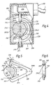
- Figur 4
- eine Variante zu
Figur 1 mit einem linear in dem Gehäuse geführten Schalterbetätigungsteil, - Figur 5
- eine weitere Detailvariante zu
Figur 1 mit geringfügig geändertem drehbaren Steuerteil und Schalterbetätigungsteil, - Figur 6
- eine gegenüber Figur 5 um 90° geklappte Ansicht derselben Detailvariante.
- Figure 1
- 1 shows a sectional view of a housing in which a rotatable control part, an electrical switch and a pivotably mounted switch actuation part are arranged,
- Figure 2
- 2 shows a sectional view folded 90 ° with respect to FIG. 1, from which it can be seen that two or more switch actuation parts and switches can be accommodated next to one another in the smallest space in the housing,
- Figure 3
- a development of two guideways arranged next to one another on the circumference of a control part for the switch actuation with a representation of the switching points of the electrical switches with respect to the angle of rotation of the control part,
- Figure 4
- 2 shows a variant of FIG. 1 with a switch actuating part guided linearly in the housing,
- Figure 5
- 1 shows a further detail variant of FIG. 1 with a slightly different rotatable control part and switch actuation part,
- Figure 6
- a view of the same detail variant folded by 90 ° relative to FIG. 5.
Eine Schalterbetätigungsvorrichtung ist gemäß Figur 1 in ein Gehäuse 101 eingebaut, in welchem ein Steuerteil 102 um eine Drehachse 102A drehbar gelagert ist. Dieses Steuerteil 102 ist hier Bestandteil eines Türschlosses in einem nicht dargestellten Kraftfahrzeug, z. B. eine Schloßnuß, die mit einem Schließzylinder in üblicher Weise über eine Drehstange drehgekuppelt ist und synchron mit diesem bei Schlüsselbetätigung des Schließzylinders zur Verriegelung bzw. Entriegelung eines Tür- oder Klappenschlosses drehbar ist. Eine solche Türschloß-Anordnung ist beispielsweise aus der bereits eingangs erwähnten Druckschrift DE 38 27 564 C1 bekannt.
Das Gehäuse 101, das - in der Zeichnung links - mit einem abnehmbaren Deckel 101D verschlossen ist, enthält auch eine Einsteckhalterung bzw. -führung 103 für wenigstens einen elektrischen Schalter 104. Aus Figur 2 wird ersichtlich, daß auch mehrere Schalter nebeneinander darin untergebracht werden können. Der in Figur 1 gezeigte elektrische Schalter 104 ist in bekannter Weise als Schnappschalter ausgeführt. Betätigungsseitig hat er einen Schaltkontakt 104S, der durch mechanische Beaufschlagung einer durch eine Totpunktfeder 104T vorgespannten Biegefeder 104B umschnappend zwischen zwei Festkontakten 104F umschaltbar ist. Anschlußseitig ist der Schalter 104 mit einer fest verlöteten Leitung L versehen.
Er hat einen Sockel 105, der in eine Steckhülse 106 eingeklipst ist, wobei die Kontakte 104S und 104F zum Schutz gegen Verschmutzung und Nässe in bekannter Weise von einer geschlossenen Schutzkappe 107 umgeben sind, die aus einem elastischen und feuchtigkeitsdichten Material, z. B. Silikon, gefertigt und mit einem Randbereich 107R zwischen dem Sockel 105 des Schalters 104 und einer Anschlagschulter 108 der Steckhülse 106 eingespannt ist. Die Steckhülse 106 selbst ist in der Einsteckführung 103 in nicht näher gezeigter Weise festgelegt.
In dem Gehäuse ist wenigstens ein Schalterbetätigungsteil 109 um eine Schwenkachse 109A, die mit Abstand parallel zu der Drehachse 102A des Steuerteils 102 verläuft, in einer Clipsaufnahme 101C schwenkbar gelagert. Dieses dient zur Übertragung bzw. Übersetzung der Drehbewegungen des Steuerteils 102 auf den Schalter 104. Es ist vollständig unabhängig von dem Schalter 104 und der Einsteckhülse 106 als ein in einen oberen Schenkel 110 und einen unteren Schenkel 111 gegabelter Schlepphebel ausgeführt. Die beiden Schenkel 110 und 111 schließen das Steuerteil 102 zwischen sich ein, wobei sie jeweils endseitig ein auf das Steuerteil 102 zu weisendes Schleifstück 112 bzw. 113 tragen, welche mit geringem Spiel oder mit nur geringer Auflagekraft auf einer Führungsbahn 114 anliegen, die längs eines Umfangs des Steuerteils 102 verläuft. Dabei liegen die beiden mit abgerundeten Spitzen versehenen Schleifstücke 112 und 113 einander etwa diametral gegenüber. Vor dem Einsetzen des Steuerteils 102 in das Gehäuse 101 wird die Drehachse des Schalterbetätigungsteils 109 in die Clipsaufnahme 101C eingeschoben.
Auf dem näher zu der Einsteckführung 103 für den Schalter 104 hin liegenden Schenkel 110 ist ein Fortsatz 115 als den Schalter 104 betätigende Kontur angeformt, der durch eine Aussparung 116 der Einsteckführung 103 und der Steckhülse 106 geführt ist und unter elastischer Verformung der geschlossenen Schutzkappe 107 die Biegefeder 104B des Schalters 104 unmittelbar beaufschlagen kann. Er wird dabei entlang einer durch die Betätigungsrichtung des Schalters 104 vorgegebenen Bewegungsrichtung geführt.
Die Führungsbahn 114 des Steuerteils 102 weist eine erste Übergangsschräge 117 und eine zweite Übergangsschräge 118 auf, die einander ebenfalls etwa diametral gegenüberliegen und gegensinnig gerichtet sind. Jeweils zwischen diesen beiden Übergangsschrägen hat die Führungsbahn zwei Abschnitte 114.0 bzw. 114.1 mit unterschiedlichen, konstanten Radien, wobei der Radius des Abschnitts 114.0 kleiner als der des Abschnitts 114.1 ist.
Die Verbindungslinie zwischen den beiden Schleifstücken schneidet die Drehachse 102A im rechten Winkel. Der Abstand zwischen den beiden Schleifstücken 112 bzw. 113 ist im dargestellten unverformten Zustand gleich der Summe aus dem größeren und dem kleineren Radius dieser Bahnabschnitte.According to FIG. 1 , a switch actuation device is installed in a
The
It has a base 105, which is clipped into a socket 106 the contacts 104S and 104F for protection against dirt and moisture are surrounded in a known manner by a closed protective cap 107, which is made of an elastic and moisture-proof material, e.g. B. silicone, and is clamped with an edge region 107R between the base 105 of the
In the housing, at least one
On the
The
The connecting line between the two contact pieces intersects the axis of
Der Schalter 104 und das Schalterbetätigungsteil 109 sind hier in unbetätigter Ruhelage (Nichtbetätigungsstellung) dargestellt. Das Schleifstück 112 liegt an dem Abschnitt 114.0 der Führungsbahn 114.
Zur Betätigung des Schalters 104 muß das Steuerteil 102 um seine Drehachse im Uhrzeigersinn gedreht werden, bis die Übergangsschräge 117 unter dem Schleifstück 112 des oberen Schenkels 110 des Schalterbetätigungsteils 109 vollständig hindurchgeführt wurde. Strichpunktiert ist eine mögliche Endstellung (Betätigungsstellung) angedeutet.
Infolgedessen wird das Schleifstück 112 von dem Abschnitt 114.0 mit kleinerem Radius auf den Abschnitt 114.1 mit größerem Radius überführt und bewegt sich dabei auf einer leicht gekrümmten, im wesentlichen radial zur Drehachse 102A verlaufenden Bahn. Es ergeben sich eine Schwenkbewegung des Schalterbetätigungsteils 109 um einen bestimmten kleinen Winkel - bezüglich seiner Schwenkachse 109A im Uhrzeigersinn gerichtet - sowie ein ebenfalls annähernd linearer Hub des Fortsatzes 115 um einen für die Betätigung des Schalters 104 ausreichenden Betrag.
In der vorliegenden Ausführung wird gleichzeitig mit der Überführung des Schleifstücks 112 auf den größeren Radius das Schleifstück 113 zwängungsfrei über die Übergangsschräge 118 auf den Bahnabschnitt 114.0 mit kleinerem Radius überführt, wobei keine elastische Verformung des Schalterbetätigungsteils 109 notwendig ist. Die sich dann ergebende Stellung des Schalterbetätigungsteils 109 ist ebenfalls strichpunktiert angedeutet.The
To actuate the
As a result, the
In the present version, the transfer takes place simultaneously of the
Soll der Schalter 104 wieder in seinen durchgezogen gezeichneten Ausgangs-Schaltzustand umgeschaltet werden, so muß der Fortsatz 115 wieder abgesenkt werden, um die Belastung der Biegefeder 104B aufzuheben. Aus der strichpunktiert angedeuteten Stellung der Übergangsschräge 117 kann diese durch Drehung des Steuerteils 102 gegen den Uhrzeigersinn wieder unter dem Schleifstück 112 durchgeführt werden, wobei dieses wieder auf den Bahnabschnitt 114.0 mit kleinerem Radius überführt wird. Gleichzeitig wird das gegenüberliegende Schleifstück 113 über die Übergangsschräge 118 wieder auf den Bahnabschnitt 114.1 mit größerem Radius überführt, wodurch eine Schwenkbewegung des des Schalterbetätigungsteils 109 um den bestimmten kleinen Winkel erzwungen wird - bezüglich der Schwenkachse 109A diesmal gegen den Uhrzeigersinn. Die Nichtbetätigungsstellung des Schalterbetätigungsteils 109 ist wiederhergestellt.If the
Die Hin- und Her-Drehung des Steuerteils 102 entspricht für den vorliegenden Anwendungsfall in einem Fahrzeug-Tür- oder Klappenschloß z. B. der Schlüsseldrehung im Schließzylinder aus einer neutralen Schlüsselabzug- bzw. -einsteckstellung in eine Verriegelungsstellung und zurück, wobei bereits durch einen kurzzeitigen Schaltimpuls des Schalters 104 z. B. eine Zentralverriegelungsanlage, eine Diebstahlsicherung oder eine Alarmanlage im Sicherungssinn eingeschaltet werden kann. Der besondere Vorteil dieser Anordnung liegt darin, daß das Gehäuse und die von diesem aufgenommenen Teile vollkommen unabhängig von dem eigentlichen Schloß und dem Schließzylinder vormontiert und eingebaut werden können.The back and forth rotation of the
Es versteht sich jedoch, daß eine derartige beschriebene Schalterbetätigungsvorrichtung auch für andere Anwendungsfälle verwendet werden kann, z. B. um bei rotierenden Steuerteilen über einen bestimmten Drehwinkel hinweg eine Schalterbetätigung sicher einzuleiten und hernach wieder aufzulösen. Wegen der mechanischen Zwangssteuerung des Schalterbetätigungsteils 109 ist hierbei eine hohe Schaltpunktgenauigkeit und Störsicherheit erreichbar.However, it is understood that such a switch actuator described can also be used for other applications, e.g. B. to safely initiate a switch operation in rotating control parts over a certain angle of rotation and then to dissolve again. Because of the mechanical positive control of the
Im vorstehend beschriebenen Anwendungsfall muß natürlich auch eine Möglichkeit zur Entsicherung bzw. Entriegelung vorgesehen sein. Figur 2 zeigt, daß auf dem Steuerteil 102 neben und parallel zu der Führungsbahn 114 eine zweite Führungsbahn 114' angeordnet ist, welche ihrerseits mit einem zweiten Schalterbetätigungsteil 109' und einem zweiten Schalter 104' korrespondiert, wie vorab anhand von Figur 1 beschrieben. Die beiden Schalterbetätigungsteile 109 und 109' sind unabhängig voneinander bewegbar, ebenso sind die beiden Schalter 104 und 104' zwar gleichartig, jedoch elektrisch und mechanisch voneinander unabhängig. Auch das zweite Schalterbetätigungsteil 109' und der zweite Schalter 104' sind in dem Gehäuse 101 untergebracht. Beide Schalterbetätigungsteile 109 und 109' sind über in ihren Schwenkachsen 109A bzw. 109A' liegende doppelseitige Lagerzapfen in die entsprechenden Clipsaufnahmen 101C bzw. 101C' eingesetzt, woraus sich eine sichere Abstützung gegen Bewegungen quer zu der gemeinsamen Schwenkachse ergibt.
Ferner ist an dem Steuerteil 102 noch eine Trichterkontur 102T angedeutet, die das Einführen der bereits erwähnten Drehstange bei der Montage des Schließzylinders erleichtert.In the application described above, of course, a possibility for unlocking or unlocking must also be provided. FIG. 2 shows that a second guideway 114 'is arranged on the
Furthermore, a funnel contour 102T is also indicated on the
Der Schalter 104 dient in der bereits vorstehend beschriebenen Weise der Erzeugung des Sicherungs-Steuersignals, während der Schalter 104' zur Erzeugung eines Entsicherungs-Steuersignals vorgesehen ist.The
Schließlich ist in Figur 3 noch eine Abwicklung der beiden nebeneinander auf dem Umfang des Steuerteils liegenden Führungsbahnen 114 und 114' dargestellt, wobei die Drehwinkel des Steuerteils 102 von einer neutralen Mittellage ausgehend sich bis - 180° linksdrehend / gegen den Uhrzeigersinn und + 180° rechtsdrehend / im Uhrzeigersinn erstrecken. Durch eine Winkelangabe "180°" wird noch einmal verdeutlicht, daß die Übergangsschrägen 117 und 118 einander auf dem Umfang des Steuerteils 102 diametral gegenüber liegen, und zwar so, daß die diametral angeordneten Schleifstücke 112 und 113 jeweils gleichzeitig auf den Beginn der jeweils nächsten Übergangsschräge auflaufen. Parallel zu den Abwicklungslinien sind die Schaltzustände der Schalter 104 bzw. 104' in logisch "0" (Grundstellung wie in Figur 1 dargestellt) bzw. logisch "1" (umgeschaltet) dargestellt. Es sei der Vollständigkeit halber angemerkt, daß die Schließzylinder üblicher Schließsysteme an Kraftfahrzeugtüren oder -klappen einen Drehbereich von maximal - 90° bis + 90° haben. Es wird aus Figur 3 deutlich, daß bei einer Rechtsdrehung des Steuerteils 102 - der eine Verschiebung der abgewickelten Führungsbahnen 114 und 114' nach rechts entspricht - der erste Schalter 104 nach etwa 30° umgeschaltet wird, während der Schalter 104' mindestens innerhalb eines Drehwinkels von + 90° in Grundstellung verbleibt. Hingegen bleibt bei einer Linksdrehung mindestens bis - 90° der Schalter 104 in Grundstellung, während der Schalter 104' bereits nach einem Winkel von etwa 30° umgeschaltet wird. Entsprechend den Schaltpunkten der Schalter 104 bzw. 104' liegen natürlich auch die Zeitpunkte, zu denen die Schalterbetätigungsteile 109 bzw. 109' verschwenkt werden. Ein gewisser Versatz zwischen den Schaltpunkten und den Anfängen der Übergangsschrägen ist durch die Formgebung der Schleifstückspitzen und Übergangsschrägen bedingt und auch konstruktiv beeinflußbar. Ersichtlich ist der Abschnitt 114.0 der Führungsbahn 114 dem Schaltzustand "0" des Schalters 104 und ist der Abschnitt 114.1 der Führungsbahn 114 dem Schaltzustand "1" des Schalters 104 zugeordnet.
Es versteht sich, daß die erwähnten Schaltpunkte beliebig durch entsprechende Gestaltung der Führungsbahnen festlegbar sind. So ist es mit der vorliegenden Schalterbetätigungsvorrichtung z. B. auch ohne weiteres möglich, den Schalter 104' bei bestimmten Drehwinkeln des Steuerteils zusätzlich zum bereits umgeschalteten Schalter 104 in den umgeschalteten Zustand zu bringen und umgekehrt. Durch geeignete (logische) Kombination und Auswertung der Schaltersignale lassen sich auf diese Weise zusätzliche Funktionen abhängig vom Drehwinkel des Steuerteils steuern.
Außerdem müssen die beiden Schleifstücke 112 und 113 nicht zwingend einander diametral gegenüber liegen, sondern können auch z. B. nur um einen Umfangswinkel von 90° oder andere Werte gegeneinander versetzt sein.Finally, FIG. 3 also shows a development of the two
It is understood that the switching points mentioned can be arbitrarily determined by appropriate design of the guideways. So it is with the present switch actuator z. B. also easily possible to bring the switch 104 'at certain angles of rotation of the control part in addition to the already switched
In addition, the two
Eine Variante zu dem schwenkbar um die Schwenkachse 109A gelagerten Schalterbetätigungsteil 109 ist in Figur 4 skizziert. Ein Schalterbetätigungsteil 209 umfaßt hier mit einem Bogenteil 210 ein Steuerteil 202, das in gleicher Weise wie das Steuerteil 102 um eine Drehachse 202A drehbar in einem Gehäuse 201 gelagert ist und auch eine gleichartige Führungsbahn 214 mit Bahnabschnitten 214.0 und 214.1 mit unterschiedlichen, konstanten Radien sowie Übergangsschrägen 217 und 218 aufweist.
In dem mit einem aufklipsbaren Deckel 201D verschließbaren Gehäuse 201 ist wieder eine Einsteckführung 203 für einen elektrischen Schalter 204 vorgesehen, der mit dem Schalter 104 aus Figur 1 baugleich ist.
Der Bogenteil 210 weist wiederum ein erstes Schleifstück 212 und ein zweites Schleifstück 213 mit abgerundeten Spitzen auf, die an der Führungsbahn 214 einander diametral gegenüberliegend anliegen und deren Abstand gleich der Summe der beiden unterschiedlichen Radien der Bahnabschnitte 214.0 und 214.1 ist.
Das Schalterbetätigungsteil 209 ist mit einem (oberen) Fortsatz 215 bzw. einem Zapfen 211 linear verschiebbar in zwei koaxialen Ausnehmungen 216 bzw. 219 des Gehäuses 201 geführt, wobei deren Achse - in der auch die Berührungspunkte der beiden Schleifstücke 212 bzw. 213 mit der Führungsbahn 214 liegen - die Drehachse 202A des Steuerteils 202 im rechten Winkel schneidet.
An den Deckel 201D ist ein Steg 201ST angeformt, dessen Stirnseite die Ausnehmung 216 des Gehäuses 201 nach dem Befestigen des Deckels links begrenzt. Somit hat die Ausnehmung 216 wie die gebohrte Ausnehmung 219 eine umlaufende Randkontur, die den Fortsatz 215 rundum radial abstützt.
Eine dritte Führungsstelle für den Bogenteil 210 wird durch zwei Rippen 220 gebildet, die an eine Innenwand des Gehäuses 201 angeformt sind, sich parallel zu der Achse der Ausnehmungen 216 bzw. 219 erstrecken und ein Segment des Bogenteils 210 verschiebbar zwischen sich aufnehmen. Insgesamt ist also das linear verschiebbare Schalterbetätigungsteil 209 durch eine Dreipunktführung gegen Verdrehung um die erwähnte Achse der Ausnehmungen 216 bzw. 219 gesichert.A variant of the
In the
The
The
A web 201ST is formed on the
A third guide point for the
Strichpunktiert ist wie in Figur 1 eine aus der dargestellten Nichtbetätigungsstellung des Schalterbetätigungsteils 209 ausgelenkte Betätigungsstellung angedeutet. Die Überführung in diese und wieder zurück durch eine Drehbewegung des Steuerteils 202 läuft gleich ab wie zu Figur 1 bereits beschrieben, mit dem einzigen Unterschied, daß hier nur eine lineare Bewegung des Schalterbetätigungsteils abläuft. Der Fortsatz 215 wirkt ersichtlich unmittelbar auf den Schalter 204 ein, äquivalent zu dem Fortsatz 115 aus Figur 1.
Es versteht sich, daß auch in dieser Ausführungsvariante wie gemäß Figur 2 mehrere Schalter 204 und Betätigungsteile 209 nebeneinander im Gehäuse 201 angeordnet werden können.Dash-dot lines, as in FIG. 1, indicate an actuation position deflected from the non-actuation position of the
It goes without saying that also in this embodiment variant 2, a plurality of
Eine weitere, im folgenden kurz beschriebene Variante zur Vorrichtung gemäß Figur 1 kann realisiert werden, indem darauf verzichtet wird, das zweite Schleifstück auf den Bahnabschnitt mit kleinerem Radius zu überführen, während das erste Schleifstück auf den Bahnabschnitt mit größerem Radius überführt wird, und statt dessen die elastische Verformung des das Steuerteil umfassenden Schalterbetätigungsteils zur Erzeugung einer Rückstellkraft genutzt wird.
Hierzu könnten z. B. in einer nicht dargestellten Ausführung die beiden Schleifstücke des Schalterbetätigungsteils bezüglich der Drehachse des Steuerteils geringfügig versetzt angeordnet sein, so daß zwar das erste Schleifstück auf der Führungsbahn läuft, jedoch das zweite Schleifstück auf einem Umfangsteil des Steuerteils mit konstantem Radius.A further variant of the device according to FIG. 1, briefly described below, can be realized by dispensing with transferring the second contact piece to the web section with a smaller radius, while the first contact piece is transferred to the web section with a larger radius, and instead the elastic deformation of the switch actuating part comprising the control part is used to generate a restoring force.
This could, for. B. in an embodiment, not shown, the two contact pieces of the switch actuating part with respect to the axis of rotation of the control part may be arranged slightly offset, so that although the first contact piece runs on the guideway, the second contact piece on a peripheral part of the control part with a constant radius.
Noch eine andere, gleichartige Möglichkeit, die ohne Achsversatz der beiden Schleifstücke auskommt, wäre darin zu sehen, daß der Führungsbahnabschnitt mit kleinerem Radius lediglich als Einsenkung mit beidseitigen Rändern ausgeführt wird, in welche ein Schleifstück eintauchen kann, während das andere Schleifstück bezüglich der Drehachse des Steuerteils so breit ausgeführt wird, daß es in diese Einsenkung nicht eintauchen kann. Eine einfache Skizze dieser letzterwähnten Anordnung findet sich in Figuren 5 und 6.Yet another, similar possibility, which does not require an axial offset of the two contact strips, would be seen in the fact that the guideway section with a smaller radius is only implemented as a depression with edges on both sides into which one contact piece can dip, while the other contact piece with respect to the axis of rotation of the Control section is so wide that it can not dive into this depression. A simple sketch of this last-mentioned arrangement can be found in FIGS. 5 and 6 .
Figur 5 zeigt als Detailvariante zu Figur 1 lediglich ein zylindrisches Steuerteil 302 in einer Teilschnittansicht, aus der hervorgeht, daß ein Abschnitt 314.0 als Einstich oder Einsenkung mit kleinerem Radius über einen Umfangswinkel von ca. 180° in das um eine Drehachse 302A drehbar gelagerte Steuerteil 302 eingeformt ist, die zweiseitig durch Ränder 320 - wie deutlicher aus Figur 6 hervorgeht - und an den anderen beiden Seiten durch Übergangsschrägen 317 bzw. 318 begrenzt ist.
Ein Schalterbetätigungsteil 309 ist gegenüber dem Schalterbetätigungsteil 109 aus Figur 1 geringfügig dadurch geändert, daß ein Schleifstück 313 an dem unteren Schenkel 311 so breit ausgeführt ist, daß es nicht in die Einsenkung des Bahnabschnitts 314.0 eintauchen kann, sondern - wie wiederum insbesondere aus Figur 6 ersichtlich - auf den Rändern 320 gleitet, wenn das Steuerteil 302 so weit gedreht wird, daß der Abschnitt 314.0 unter dieses Schleifstück gelangt. Letzterer Zustand ist durch gestrichelte Darstellung des Abschnitts 314.0 an der Unterseite des Steuerteils 302 angedeutet. Hingegen kann das Schleifstück 312 des oberen Schenkels 310, dem wiederum ein Fortsatz 315 unmittelbar gegenüberliegt, in die Einsenkung eintauchen, wie dargestellt. Es ist zwingend notwendig, den Fortsatz 315 dem über die Übergangsschräge 317 radial zur Drehachse 302A beweglichen Schleifstück 312 zuzuordnen.
Auch in dieser Ausführung ist eine Führungsbahn 314 für das Schalterbetätigungsteil 309 auf der Umfangslinie, auf der die Abschnitte 314.0 und 314.1 angeordnet sind, gebildet.FIG. 5 shows, as a detailed variant of FIG. 1, only a
A
In this embodiment too, a
In dieser Ausgestaltung kommt es bei der Überführung des Schleifstücks 312 aus dem Abschnitt 314.0 auf den Abschnitt 314.1 des Umfangs des Steuerteils 302 zu einer Aufspreizung des Winkels zwischen den beiden Schenkeln 310 und 311, die aufgrund der Elastizität des Schalterbetätigungsteils 309 eine Vorspannkraft bewirkt. Wie aus der strichpunktiert angedeuteten Stellung hervorgeht, wird lediglich der obere Schenkel 310 des Schalterbetätigungsteils 309 und mit ihm dessen Fortsatz 315 angehoben, wodurch ein zugeordneter Schalter umgeschaltet werden kann. Es versteht sich, daß das Schalterbetätigungsteil 309 hinreichend steif gegen Kippbewegungen und Torsionsverformung dimensioniert ist.
Wird nun das Schleifstück 312 wieder auf den Abschnitt 314.0 zurückgeführt, so bewirkt die genannte Vorspannkraft, daß es auch wirklich auf den kleineren Radius der Einsenkung hinabgleitet. Folglich gibt der Fortsatz 315 auch in dieser Konfiguration den Schalter zwangsläufig wieder frei, ohne daß hierzu eine eigene Rückstellfeder vorgesehen werden muß.
Die Umfangslänge der Einsenkung gewährleistet auch in dieser Anordnung, daß bei einer Drehung des Steuerteils 302 gegen den Uhrzeigersinn - speziell wiederum bei einer Doppelschalter-Anordnung wie gemäß Figur 2 - ein relativ großer Drehwinkel ohne Betätigung des Schalters möglich ist.
Eine Schwenklagerung des Schalterbetätigungsteils 309 muß hier nicht zwingend vorgesehen sein, vielmehr sind auch einschenklige Ausführungen in der Art einer Blattfeder bzw. eines elastischen Schlepphebels denkbar.
Auch in dieser Variante ist die diametrale Anordnung der Schleifstücke 312 und 313 nicht zwingend funktionsnotwendig. Es sind vielmehr auch Umfangswinkel bzw. -versätze im Bereich zwischen 90 und 180° zwischen den Schleifstück-Berührungspunkten mit der jeweiligen Führungsbahn konstruktiv realisierbar, wobei aber weitere Vorkehrungen für den zwängungsfreien Lauf der Schleifstücke auf der Führungsbahn getroffen werden müssen und insbesondere der Achsabstand zwischen der Drehachse des Steuerteils und der Schwenkachse des Schalterbetätigungsteils gegenüber den gezeigten Anordnungen verringert werden muß.In this embodiment, when the
Now the
The circumferential length of the depression also ensures in this arrangement that a relatively large angle of rotation is possible without actuating the switch when the
A swivel mounting of the
In this variant, too, the diametrical arrangement of the contact strips 312 and 313 is not absolutely necessary for the function. Rather, circumferential angles or offsets in the range between 90 and 180 ° between the contact points of the contact strip with the respective guideway can be implemented constructively, but further precautions must be taken for the constraint-free running of the contact strips on the guideway and in particular the center distance between the Axis of rotation of the control part and the pivot axis of the switch actuating part must be reduced compared to the arrangements shown.
Claims (10)
- A device for the mechanical actuation of at least one electric switch, consisting of- a housing (101),- a mount (103) for the electric switch (104, 204, 304) in the housing (101),- a control element (102, 202, 302) located in the housing (101), which can be moved by means of externally exerted force, fitted with at least one guideway (114, 214, 314),- a switch actuator (109, 209, 309) located in the housing (101) which can be guided mechanically back and forth between an actuation and a non-actuation position along the guideway (114, 214, 314) by moving the control element (102, 202, 302) which acts mechanically upon the switch (104, 203, 304) with a profile (115, 215, 315) - guided in a direction determined by the direction of actuation of the switch - thus commuting it,characterised by- the position of the control element (102; 202; 302) such that it rotates about a rotational axis (102A; 202A; 302A),- the position of at least one guideway (114; 214; 314) around the circumference of the control element (102; 202; 302) about the rotational axis (102A; 202A; 302A), whereby the guideway has at least two slanted edges (117, 118; 217, 218; 317, 318) pointing in opposite directions both positioned between two sections of the guideway (114.0, 114.1; 214.0, 214.1; 314.0, 314.1) with constant radii of different sizes,- the form (leg 110, 111; 310, 311; curved section 210) of the switch actuator (109; 209; 309) which surrounds the control element (120; 202; 302) in the area of the guideway (114; 214; 314) for a limited part of its circumference,
whereby- the actuator is fitted with a first and a second contact head (112, 113; 212, 213; 312, 313) which rest on almost diametrically opposed points of the guideway (114; 214; 314) and- the distance between the contact heads (112, 113; 212, 213; 312, 313) when the switch actuator (109; 209; 309) is in its un-deformed state corresponds to the sum of the smaller and the greater radii of the sections (114.0, 114.1; 214.0, 214.1; 314.0, 314.1) of the guideway,- the position of the profile (extension 115; 215; 315) which acts mechanically upon the switch (104, 204) in relation to a contact head (112; 212; 312) on the switch actuator (109; 209; 309) which moves radially over one of the slanted edges (117; 217; 317) in relation to the rotating control element (201; 202; 302) in such a way that the direction of movement of the profile (115; 215; 315) caused by the movement of the contact head (112; 212; 312) is also essentially radial to the rotational axis of the control element (102A; 202A; 302A) in the direction of actuation of the switch (104; 204). - A device in accordance with claim 1, in which the switch actuator is located in the housing and can be pivoted about a swivelling axis,
characterised by- the position of the swivelling axis (109A; 309A) of the switch actuator (109; 309) at a distance parallel to the rotational axis of the control element (102A; 302A),- the forked design of the switch actuator (109; 309) with a first leg (110; 311) and a second leg (112; 312), whereby
- the two legs (110, 111; 310, 311) extending from the swivelling axis (109A; 309A) surround the control element (102; 302) in the region of the guideway (114; guideway sections 314.0, 314.1) and the ends of which are fitted with contact heads (112, 113; 312. 313) which rest on the guideway (114), and- the position of the profile (115; 315) which acts mechanically upon the switch (104) on a leg (112; 312) of the switch actuator (9; 9') which can be moved radially in relation to the control element (102; 302) by means of a slanted edge (117; 317). - A device in accordance with claim 1,
characterised by- the design of the switch actuator (209) with a curved section (210) which surrounds the control element (202) over an angle at circumference of at least 180 and at the ends of which are located the contact heads (212, 213) which rest on the guideway (214),- the linear guiding of the switch actuator (209) by parts (extension 215, pin 211) which project into recesses (216, 219) in the housing (201),
whereby the points at which the contact heads (212, 213) touch the guideway (214) and the axes of the recesses (216, 219) which guide the switch actuator (209) linearly lie on a straight line which cuts the radial axis (202A) of the control element (202) at right angles. - A device in accordance with claims 1 or 2 or 3,
characterised by,
- the positioning of the two slanted edges (117, 118; 217, 218) of the guideway (114; 214) according to the position of the contact heads (112, 113; 212, 213) of the switch actuator (109; 209) in relation to the circumference of the control element (102; 202),
whereby in order to actuate the switch (104; 204) one (112; 212) of the contact heads can pass over one (117; 217) of the slanted edges out of the section (114.0; 214.0) of the guideway with the smaller radius into the section (114.1; 214.1) with the larger radius with a rotational movement of the control element (102; 202) and, at the same time, the other contact head (113; 213) can pass without exerting any fore over the other slanted edge (118; 218) from the section (114.1; 214.1) with the larger radius into the section (114.0; 214.0) of the guideway with the smaller radius. - A device in accordance with claim 1 or 2,
characterised in that,
during the radial movement of the first contact head (312) of the switch actuator (309) in relation to the rotating control element (302) the other contact head (313) slides on a constant radius (guideway section 314.1, edges 320), whereby the change in the distance between the two contact heads (312, 313) causes an elastic deformation of the switch actuator (309) and produces pre-tensile forces which cause the first contact head to return. - A device in accordance with claim 5,
characterised by- the design of the guideway section (314.0) with the smaller radius as a hollow bounded by the slanted edges (317, 318) and the edges (320) running around the circumference of the control element (302) with an external radius corresponding to the radius of the guideway section (314.1) with the larger radius,- the design of the first contact head (312) in a form allowing it to project into the hollow and the second contact head (313) in a form preventing it from projecting into the hollow. - A device in accordance with one of the preceding claims,
characterised by
- several, notably two, guideways (114, 114') running parallel to each other on the control element (102) to each of which one switch actuator (109, 109') is allocated to actuate one switch (104, 104'). - A device in accordance with one of the preceding claims in which the electric switch is designed as a snap-action switch.
- A device in accordance with one of the preceding claims in which the control element (102; 202; 302) is the nut lock of a lock locked by means of a lock cylinder.
- A device in accordance with one of the preceding claims,
characterised by- the design of the contact heads (112, 113; 212, 213; 312, 313) with rounded ends and- the design of the slanted edges (117, 118; 217, 218; 317, 318) as even gradients.
Applications Claiming Priority (2)
| Application Number | Priority Date | Filing Date | Title |
|---|---|---|---|
| DE4039442 | 1990-12-11 | ||
| DE4039442A DE4039442C1 (en) | 1990-12-11 | 1990-12-11 |
Publications (2)
| Publication Number | Publication Date |
|---|---|
| EP0490142A1 EP0490142A1 (en) | 1992-06-17 |
| EP0490142B1 true EP0490142B1 (en) | 1994-03-02 |
Family
ID=6420017
Family Applications (1)
| Application Number | Title | Priority Date | Filing Date |
|---|---|---|---|
| EP91119953A Expired - Lifetime EP0490142B1 (en) | 1990-12-11 | 1991-11-22 | Switch actuator |
Country Status (3)
| Country | Link |
|---|---|
| EP (1) | EP0490142B1 (en) |
| DE (1) | DE4039442C1 (en) |
| ES (1) | ES2052316T3 (en) |
Families Citing this family (7)
| Publication number | Priority date | Publication date | Assignee | Title |
|---|---|---|---|---|
| GB2264743A (en) * | 1992-02-25 | 1993-09-08 | Ford Motor Co | Door latch and lock assembly |
| DE4222798C2 (en) * | 1992-07-10 | 1995-07-13 | Daimler Benz Ag | Assembly of a lock having a lock cylinder with a neutral key withdrawal position and an actuating element fastened to a lock carrier |
| FR2697488B1 (en) * | 1992-11-03 | 1995-01-06 | Vachette Ymos | Steering anti-theft device for a motor vehicle, and key for such a device. |
| DE19632995C2 (en) * | 1996-08-16 | 2000-08-24 | Kiekert Ag | Motor vehicle door lock with a plurality of switches and a switch actuation system |
| GB0029058D0 (en) | 2000-11-29 | 2001-01-10 | Meritor Light Vehicle Sys Ltd | Actuator |
| KR20130066347A (en) * | 2011-12-12 | 2013-06-20 | 현대자동차주식회사 | Apparatus and method for max opening angle setting of power tail gate |
| WO2016200743A1 (en) | 2015-06-08 | 2016-12-15 | Illinois Tool Works Inc. | Door lock operator having different types of door lock operation |
Family Cites Families (7)
| Publication number | Priority date | Publication date | Assignee | Title |
|---|---|---|---|---|
| FR2136973B1 (en) * | 1971-05-07 | 1973-05-11 | Crouzet Sa | |
| DD122595A1 (en) * | 1975-10-31 | 1976-10-12 | ||
| DE2936821C2 (en) * | 1979-09-12 | 1983-10-06 | Daimler-Benz Ag, 7000 Stuttgart | Pneumatic central locking system for a motor vehicle |
| DE3434962A1 (en) * | 1984-09-22 | 1986-03-27 | Daimler-Benz Ag, 7000 Stuttgart | Lock switch, especially motor-vehicle door-lock switch |
| DE3729303A1 (en) * | 1987-09-02 | 1989-03-16 | Licentia Gmbh | Switching apparatus |
| DE3804838C1 (en) * | 1988-02-17 | 1989-01-26 | Vdo Adolf Schindling Ag, 6000 Frankfurt, De | |
| DE3827564C2 (en) * | 1988-08-13 | 1993-12-23 | Daimler Benz Ag | Locking device for vehicles |
-
1990
- 1990-12-11 DE DE4039442A patent/DE4039442C1/de not_active Expired - Fee Related
-
1991
- 1991-11-22 EP EP91119953A patent/EP0490142B1/en not_active Expired - Lifetime
- 1991-11-22 ES ES91119953T patent/ES2052316T3/en not_active Expired - Lifetime
Also Published As
| Publication number | Publication date |
|---|---|
| ES2052316T3 (en) | 1994-07-01 |
| EP0490142A1 (en) | 1992-06-17 |
| DE4039442C1 (en) | 1992-01-30 |
Similar Documents
| Publication | Publication Date | Title |
|---|---|---|
| DE3616122A1 (en) | STEERING AND IGNITION LOCK | |
| EP0490142B1 (en) | Switch actuator | |
| WO2007019909A1 (en) | Ignition device for a motor, especially in a motor vehicle | |
| DE3408623A1 (en) | Setting device, especially for door locking on motor vehicles | |
| EP0945304A2 (en) | Process and device for automatically returning a switch associated with the direction of rotation to a neutral position | |
| EP0840336A2 (en) | Self-adjusting tappet-switch, in particular brake ligth switch | |
| EP0294512B1 (en) | Electrical switch, particularly for steering column switch for vehicle | |
| DE2951356C2 (en) | Device for mechanical switch-on blocking of one of two switching elements as long as the other switching element is in the switched-on position | |
| EP0881707B1 (en) | Electric switch | |
| DE2250738B2 (en) | Adapter for a U-shaped, multi-pole busbar | |
| DE10106228A1 (en) | Safety switch with unlocking disc | |
| DE2157462C3 (en) | Ignition switches for automobiles | |
| EP0012175B1 (en) | Spark or glow ignition switch for motor vehicles | |
| DE3803125C1 (en) | Electrical switch | |
| EP0967350A1 (en) | Electric motor actuator for a motor vehicle lock | |
| EP0061574B1 (en) | Limit switch | |
| DE19702251C2 (en) | Central locking actuator for doors or flaps of motor vehicles | |
| DE2606698A1 (en) | LOCK | |
| DE2803768C3 (en) | Electrical cam switch with coupled rotary switch | |
| DE19631950C2 (en) | switch module | |
| DE19812251C2 (en) | Electric rotary switch | |
| DE2036736C3 (en) | Electrical switch with an axially displaceable driver in which a key engages | |
| EP0648626B1 (en) | Coupling device for vane arrangement | |
| EP0617446B1 (en) | Control apparatus, particularly power control apparatus for electric heating apparatus | |
| EP0093314B1 (en) | Switch |
Legal Events
| Date | Code | Title | Description |
|---|---|---|---|
| PUAI | Public reference made under article 153(3) epc to a published international application that has entered the european phase |
Free format text: ORIGINAL CODE: 0009012 |
|
| 17P | Request for examination filed |
Effective date: 19920409 |
|
| AK | Designated contracting states |
Kind code of ref document: A1 Designated state(s): ES FR GB IT NL SE |
|
| 17Q | First examination report despatched |
Effective date: 19930727 |
|
| GRAA | (expected) grant |
Free format text: ORIGINAL CODE: 0009210 |
|
| ITF | It: translation for a ep patent filed |
Owner name: BARZANO' E ZANARDO ROMA S.P.A. |
|
| AK | Designated contracting states |
Kind code of ref document: B1 Designated state(s): ES FR GB IT NL SE |
|
| GBT | Gb: translation of ep patent filed (gb section 77(6)(a)/1977) |
Effective date: 19940405 |
|
| ET | Fr: translation filed | ||
| REG | Reference to a national code |
Ref country code: ES Ref legal event code: FG2A Ref document number: 2052316 Country of ref document: ES Kind code of ref document: T3 |
|
| PLBE | No opposition filed within time limit |
Free format text: ORIGINAL CODE: 0009261 |
|
| STAA | Information on the status of an ep patent application or granted ep patent |
Free format text: STATUS: NO OPPOSITION FILED WITHIN TIME LIMIT |
|
| EAL | Se: european patent in force in sweden |
Ref document number: 91119953.7 |
|
| 26N | No opposition filed | ||
| NLS | Nl: assignments of ep-patents |
Owner name: MARQUARDT GMBH;DAIMLER-BENZ AKTIENGESELLSCHAFT |
|
| REG | Reference to a national code |
Ref country code: FR Ref legal event code: TP |
|
| REG | Reference to a national code |
Ref country code: GB Ref legal event code: 732E |
|
| NLS | Nl: assignments of ep-patents |
Owner name: DAIMLERCHRYSLER AG;MARQUARDT GMBH |
|
| REG | Reference to a national code |
Ref country code: GB Ref legal event code: 732E |
|
| PGFP | Annual fee paid to national office [announced via postgrant information from national office to epo] |
Ref country code: GB Payment date: 20010316 Year of fee payment: 10 Ref country code: FR Payment date: 20010316 Year of fee payment: 10 |
|
| PGFP | Annual fee paid to national office [announced via postgrant information from national office to epo] |
Ref country code: SE Payment date: 20010319 Year of fee payment: 10 |
|
| PGFP | Annual fee paid to national office [announced via postgrant information from national office to epo] |
Ref country code: ES Payment date: 20010323 Year of fee payment: 10 |
|
| PGFP | Annual fee paid to national office [announced via postgrant information from national office to epo] |
Ref country code: NL Payment date: 20010326 Year of fee payment: 10 |
|
| PG25 | Lapsed in a contracting state [announced via postgrant information from national office to epo] |
Ref country code: GB Free format text: LAPSE BECAUSE OF NON-PAYMENT OF DUE FEES Effective date: 20011122 |
|
| PG25 | Lapsed in a contracting state [announced via postgrant information from national office to epo] |
Ref country code: SE Free format text: LAPSE BECAUSE OF NON-PAYMENT OF DUE FEES Effective date: 20011123 Ref country code: ES Free format text: LAPSE BECAUSE OF NON-PAYMENT OF DUE FEES Effective date: 20011123 |
|
| REG | Reference to a national code |
Ref country code: GB Ref legal event code: IF02 |
|
| PG25 | Lapsed in a contracting state [announced via postgrant information from national office to epo] |
Ref country code: NL Free format text: LAPSE BECAUSE OF NON-PAYMENT OF DUE FEES Effective date: 20020601 |
|
| EUG | Se: european patent has lapsed |
Ref document number: 91119953.7 |
|
| GBPC | Gb: european patent ceased through non-payment of renewal fee |
Effective date: 20011122 |
|
| PG25 | Lapsed in a contracting state [announced via postgrant information from national office to epo] |
Ref country code: FR Free format text: LAPSE BECAUSE OF NON-PAYMENT OF DUE FEES Effective date: 20020730 |
|
| NLV4 | Nl: lapsed or anulled due to non-payment of the annual fee |
Effective date: 20020601 |
|
| REG | Reference to a national code |
Ref country code: FR Ref legal event code: ST |
|
| REG | Reference to a national code |
Ref country code: FR Ref legal event code: ST |
|
| REG | Reference to a national code |
Ref country code: ES Ref legal event code: FD2A Effective date: 20021213 |
|
| PG25 | Lapsed in a contracting state [announced via postgrant information from national office to epo] |
Ref country code: IT Free format text: LAPSE BECAUSE OF NON-PAYMENT OF DUE FEES Effective date: 20051122 |