EP0489410A1 - Device for sharpening drill bits - Google Patents
Device for sharpening drill bits Download PDFInfo
- Publication number
- EP0489410A1 EP0489410A1 EP91120783A EP91120783A EP0489410A1 EP 0489410 A1 EP0489410 A1 EP 0489410A1 EP 91120783 A EP91120783 A EP 91120783A EP 91120783 A EP91120783 A EP 91120783A EP 0489410 A1 EP0489410 A1 EP 0489410A1
- Authority
- EP
- European Patent Office
- Prior art keywords
- grinding
- drill
- central axis
- sharpening
- grinding wheel
- Prior art date
- Legal status (The legal status is an assumption and is not a legal conclusion. Google has not performed a legal analysis and makes no representation as to the accuracy of the status listed.)
- Granted
Links
- 230000001154 acute effect Effects 0.000 claims description 2
- 230000015572 biosynthetic process Effects 0.000 abstract description 4
- 230000007423 decrease Effects 0.000 description 4
- 230000003247 decreasing effect Effects 0.000 description 1
- 238000011161 development Methods 0.000 description 1
- 230000018109 developmental process Effects 0.000 description 1
- 230000002093 peripheral effect Effects 0.000 description 1
- 230000002035 prolonged effect Effects 0.000 description 1
- 230000000717 retained effect Effects 0.000 description 1
Images
Classifications
-
- B—PERFORMING OPERATIONS; TRANSPORTING
- B24—GRINDING; POLISHING
- B24B—MACHINES, DEVICES, OR PROCESSES FOR GRINDING OR POLISHING; DRESSING OR CONDITIONING OF ABRADING SURFACES; FEEDING OF GRINDING, POLISHING, OR LAPPING AGENTS
- B24B3/00—Sharpening cutting edges, e.g. of tools; Accessories therefor, e.g. for holding the tools
- B24B3/24—Sharpening cutting edges, e.g. of tools; Accessories therefor, e.g. for holding the tools of drills
- B24B3/26—Sharpening cutting edges, e.g. of tools; Accessories therefor, e.g. for holding the tools of drills of the point of twist drills
- B24B3/265—Sharpening cutting edges, e.g. of tools; Accessories therefor, e.g. for holding the tools of drills of the point of twist drills using devices specially adapted for domestic use
Landscapes
- Engineering & Computer Science (AREA)
- Mechanical Engineering (AREA)
- Finish Polishing, Edge Sharpening, And Grinding By Specific Grinding Devices (AREA)
- Polishing Bodies And Polishing Tools (AREA)
- Drilling Tools (AREA)
Abstract
Description
Die Erfindung bezieht sich auf eine Bohrerschleifeinrichtung gemäß dem Oberbegriff des Anspruchs 1.The invention relates to a drill grinding device according to the preamble of
Eine solche ist durch die US-PS 4,574,529 bekannt. Bei der dortigen Schleifscheibe geht das dem Bohrerführungsstück am nächsten liegende Ende der konischen Schleiffläche in einen senkrecht zur Mittelachse liegenden Flächenabschnitt der Schleifscheibe über. Auf Grund der besonderen Geometrie von Spiralbohrern - die größte wegzuschleifende Materialmenge liegt an der Peripherie der Bohrer - erfolgt die größte Abnützung der Schleifscheibe an dem dem Bohrerführungsstück am nächsten liegenden Ende der Schleiffläche und nimmt mit zunehmender Entfernung davon kontinuierlich ab. Dies führt zur alsbaldigen Bildung einer etwas abgerundeten Stufe in der Schleifscheibe an dem besagten Ende der Schleiffläche. Eine entsprechende konvexe Abrundung des peripheren Bereiches der Bohrerhauptschneiden entsteht und verschlechtert deren Schneideigenschaften in zunehmendem Maße. Es ist deshalb eine Richtanordnung vorgesehen, welche die von den Bohrern weniger abgenützten Bereiche der Schleiffläche und den senkrecht zur Mittelachse liegenden Flächenabschnitt der Schleifscheibe entsprechend abnützt, sodaß eine solche Stufenbildung verhindert und der Anstiegswinkel der Schleiffläche erhalten bleibt. Es ist Aufgabe der Erfindung, eine gattungsgemäße Einrichtung zu schaffen, bei welcher eine Stufenbildung in der Schleifecheibe auch ohne zusätzliche Richtanordnung unterbleibt.One such is known from US Pat. No. 4,574,529. In the grinding wheel there, the end of the conical grinding surface that is closest to the drill guide piece merges into a surface section of the grinding wheel that is perpendicular to the central axis. Due to the special geometry of twist drills - the largest amount of material to be ground away is at the periphery of the drills - the greatest wear of the grinding wheel occurs at the end of the grinding surface closest to the drill guide piece and decreases continuously with increasing distance from it. This leads to the immediate formation of a somewhat rounded step in the grinding wheel at the said end of the grinding surface. A corresponding convex rounding of the peripheral area of the main cutting edges arises and increasingly deteriorates their cutting properties. A straightening arrangement is therefore provided which correspondingly wears out the areas of the grinding surface which are less worn by the drills and the surface section of the grinding wheel which is perpendicular to the central axis, so that such a step formation is prevented and the angle of rise of the grinding surface is retained. It is an object of the invention to provide a generic device in which there is no step formation in the grinding wheel even without an additional straightening arrangement.
Gelöst ist diese Aufgabe durch die im Anspruch 1 angegebene Erfindung.This object is achieved by the invention specified in
Die Unteransprüche sind vorteilhafte Weiterbildungen der erfindungsgemäßen Einrichtung.The subclaims are advantageous developments of the device according to the invention.
In einer erfindungsgemäßen Einrichtung kann an dem dem Bohrerführungsstück am nächsten liegenden Ende der Schleiffläche keine Stufe in der Schleifscheibe entstehen, da außerhalb dieses Endes, in radialer Richtung gesehen, kein Schleifscheibenmaterial vorhanden ist. Eine Abrundung der äußeren Enden der Bohrerhauptschneiden findet somit nicht statt. Der Anstiegswinkel der Schleiffläche verringert sich zwar, mit einer Zunahme des Spitzenwinkels der Bohrer zur Folge, was jedoch,innerhalb gewisser Grenzen, tolerierbar ist. Es sind zwar Einrichtungen, beispielsweise durch die US-PS 3753320, bekannt, bei denen eine konische Schleiffläche am ihrem dem Bohrerführungsstück am nächsten liegenden Ende mit dem daran anschließenden Flächenabschnitt der Schleifscheibe einen spitzwinkeligen Grat bildet. Jedoch sind dort die Führungskanäle so angeordnet, daß ihre Zentrumachsen das vom Bohrerführungsstück am weitesten entfernte Ende der Schleiffläche treffen.In a device according to the invention, no step can arise in the grinding wheel at the end of the grinding surface closest to the drill guide piece, since, seen in the radial direction, no grinding wheel material is present outside this end. The outer ends of the main cutting edges are therefore not rounded. The angle of rise of the grinding surface decreases, with an increase in the tip angle of the drills as a result, which, however, is tolerable within certain limits. There are Although devices, for example by US-PS 3753320, are known in which a conical grinding surface at its end closest to the drill guide piece forms an acute-angled ridge with the adjoining surface section of the grinding wheel. However, the guide channels are arranged there in such a way that their center axes meet the end of the grinding surface furthest away from the drill guide piece.
Ein Ausbrechen größerer Stücke der Schleifscheibe am Grat wird gemäß einem weiteren Erfindungsmerkmal dadurch verhindert, daß der zusammen mit der Schleiffläche den Grat bildende Flächenabschnitt der Schleifscheibe ebenfalls konisch ist.A further feature of the invention prevents large pieces of the grinding wheel from breaking out on the ridge in that the surface section of the grinding wheel forming the burr together with the grinding surface is also conical.
Ein besonders effizienter Materialtransport von der Schleiffläche wird gemäß einem weiteren Erfindungsmerkmal dadurch erreicht, daß die Schleiffläche ein Außenkonus ist.A particularly efficient material transport from the grinding surface is achieved according to a further feature of the invention in that the grinding surface is an outer cone.
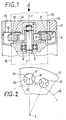
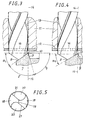
Nachstehend wird die Erfindung anhand eines in den Zeichnungen dargestellten Ausführungsbeispiels näher erläutert. Es zeigen Fig. 1 einen Längsschnitt durch das Ausführungsbeispiel, Fig. 2 eine Draufsicht auf zwei Führungskanäle, gesehen in der Richtung des Pfeiles A in Fig. 1, in größerem Maßstab, Fig. 3 einen Ausschnitt aus Fig. 1 mit einem in einen Führungskanal bis zur Schleiffläche eingeführten Bohrer, in größerem Maßstab, Fig. 4 wie Fig. 3, jedoch nach längerer Abnützung der Schleifscheibe, Fig. 5 eine Draufsicht auf eine Bohrerspitze.The invention is explained in more detail below on the basis of an exemplary embodiment shown in the drawings. 1 shows a longitudinal section through the exemplary embodiment, FIG. 2 shows a plan view of two guide channels, seen in the direction of arrow A in FIG. 1, on a larger scale, FIG. 3 shows a detail from FIG. 1 with one into a
Die verschiedenen Teile des Ausführungsbeispiels sind konzentrisch um die Mittelachse 1 angeordnet.The various parts of the exemplary embodiment are arranged concentrically around the
Eine Achse 2 ist die Spindel eines im Gehäuse 3 angeordneten, nicht dargestellten Motors. Die Achse 2 ist in Kugellagern 4 axial fixiert gelagert.An
Auf der Achse 2 ist ein Schleifscheibenträger 5 zwischen dem Lager 4 und der Mutter 6 befestigt.On the
Mit dem Schleifscheibenträger 5 ist eine ringförmige Schleifscheibe 7 verleimt. Die Schleifscheibe besitzt an ihrer vom Motor abgewandten Flanke eine außenkonische Schleiffläche 8, die zusammen mit einem Innenkonus 9 einen spitzwinkeligen Grat 10 bildet. Die Schleiffläche 8 bildet mit ihrer Rotationsebene den Winkel α₁ von 35°, der Innenkonus 9 den Winkel β von 75°. Dies ergibt den spitzen Winkel γ von 70° am Grat 10.An annular grinding wheel 7 is glued to the grinding
Gegenüber der Schleiffläche 8 ist ein Bohrerführungsstück 11, 12 angeordnet. Dieses ist mit dem Gehäuse 3 starr verbunden und setzt sich aus einem Führungskanalkörper 11 und einer mit diesem starr verbundenen Führungszapfenplatte 12 zusammen.A
Der Führungskanalkörper 11 weist zur Mittelachse 1 parallele Führungskanäle 13 verschiedener Durchmesser auf, welche einen mit der Mittelachse 1 gleichachsigen, gedachten Zylindermantel 14 außen tangieren. Der Durchmesser des Zylindermantels 14 ist gleich dem Durchmesser des Grates 10 der Schleifscheibe.The
Die Führungszapfenplatte 12 besitzt mit den Führungskanälen 13 fluchtende Öffnungen 15, in die je zwei zum Eingriff in die Spannuten 20 eines in den Führungskanal eingeführten Bohrers bestimmte, trapezförmige Führungszapfen 16 ragen. Diese besitzen je zwei Anschlagkanten 17 und sind so bemessen, daß sie eine etwa 30°- Drehung um seine Achse des in den Führungskanal eingeführten Bohrers gestatten.The
Der zu schleifende Bohrer wird mit der Hand in den kleinsten passenden Führungskanal 13 und zwischen den Führungszapfen 16 darin bis zum Anschlagen einer seiner Hinterschlifflächen 18 gegen die rotierende Schleiffläche 8 eingeführt. Dabei berührt die Peripherie des Bohrers annähernd den Grat 10. Der leicht gegen die Schleiffläche gedrückte Bohrer wird nun zwischen den Anschlagkanten 17 der Führungszapfen einige Male hin- und hergedreht. Er wird danach etwas zurückgezogen, um 180° gedreht, wieder bis zur Schleiffläche eingeführt und hin- und hergedreht. Beide Hinterschlifflächen sind nun geschliffen.The drill to be ground is inserted by hand into the smallest
Auf Grund der besonderen Geometrie von Siralbohrern(siehe Fig. 5) ist die Abnützung der Schleifscheibe unmittelbar am Grat 10 am größten und nimmt mit zunehmender Entfernung vom Grat kontinuierlich ab. Im Bereich der Querschneide 19 des Bohrers ist die Abnützung der Schleifscheibe geringfügig. Der Anstiegswinkel α der Schleiffläche 8 wird sich deshalb mit zunehmender Abnützung der Schleifscheibe verringern. Wenn sich der Anstiegswinkel α der Schleiffläche auf etwa 30° (α₂ in Fig. 4) verringert hat, wird die Schleifscheibe ausgewechselt. Eine Stufe in der Schleifscheibe am gratseitigen Ende der Schleiffläche kann jedoch nicht entstehen, da außerhalb dieses Endes der Schleiffläche, in radialer Richtung gesehen, kein Schleifscheibenmaterial vorhanden ist. Die Hauptschneiden 21 der Bohrer verbleiben immer gerade. Ein gewisser, von der verwendeten Korngröße im Schleifkörper abhängiger Überstand der Lage des Grates 10 in bezug auf die Bohrerperipherie - siehe Fig. 3 und Fig. 4 - ist jedoch nicht von Nachteil, da dieser abbröckelt. Der Anstiegswinkel β des innenkonischen Flächenabschnittes 9 der Schleifscheibe ist deshalb so zu wählen, daß einerseits ein Ausbrechen größerer Stücke der Schleifscheibe am Grat 10 verhindert wird, andererseits der erwähnte Überstand des Grates 10 mit zunehmender Abnützung der Schleifscheibe nicht zu groß wird. Loses Material wird bei rotierender Schleifscheibe durch die Wirkung der Zentrifugalkraft von der außenkonischen Schleiffläche 8 weggeschleudert.Due to the special geometry of siral drills (see FIG. 5), the wear of the grinding wheel is greatest directly on the
Claims (4)
Applications Claiming Priority (2)
| Application Number | Priority Date | Filing Date | Title |
|---|---|---|---|
| DE4038524A DE4038524A1 (en) | 1990-12-03 | 1990-12-03 | DRILL GRINDING DEVICE |
| DE4038524 | 1990-12-03 |
Publications (2)
| Publication Number | Publication Date |
|---|---|
| EP0489410A1 true EP0489410A1 (en) | 1992-06-10 |
| EP0489410B1 EP0489410B1 (en) | 1997-09-24 |
Family
ID=6419494
Family Applications (1)
| Application Number | Title | Priority Date | Filing Date |
|---|---|---|---|
| EP91120783A Expired - Lifetime EP0489410B1 (en) | 1990-12-03 | 1991-12-03 | Device for sharpening drill bits |
Country Status (6)
| Country | Link |
|---|---|
| US (1) | US5210977A (en) |
| EP (1) | EP0489410B1 (en) |
| JP (1) | JP2556790B2 (en) |
| AU (1) | AU646905B2 (en) |
| CA (1) | CA2056162A1 (en) |
| DE (2) | DE4038524A1 (en) |
Families Citing this family (10)
| Publication number | Priority date | Publication date | Assignee | Title |
|---|---|---|---|---|
| US5788559A (en) * | 1994-02-25 | 1998-08-04 | Jungnitsch; Paul Lewis | Web adjust drill bit sharpener and method of using |
| US5564871A (en) * | 1994-06-16 | 1996-10-15 | Lagsdin; Andry | Chamfer machine |
| US5676591A (en) * | 1996-08-13 | 1997-10-14 | Huang; Cheng-Hsien | Bit sharpener |
| US9199315B2 (en) | 2000-06-02 | 2015-12-01 | Kennametal Inc. | Twist drill and method for producing a twist drill which method includes forming a flute of a twist drill |
| US6676500B1 (en) * | 2002-11-12 | 2004-01-13 | Sophin Lin | Drill bit sharpener |
| JP2005262341A (en) * | 2004-03-16 | 2005-09-29 | Noritake Super Abrasive:Kk | Cmp pad conditioner |
| US7488239B2 (en) * | 2006-11-08 | 2009-02-10 | Rolf Tamm | Assembly for grinding electrodes |
| DE102009044855A1 (en) * | 2009-12-10 | 2011-06-16 | Rolf Tamm | Kit for retrofitting an electrode grinding device and electrode grinding device |
| US8690643B2 (en) * | 2010-07-06 | 2014-04-08 | Western New England University | Portable drill bit sharpener |
| CN102126952A (en) * | 2010-12-17 | 2011-07-20 | 张家港瀚康化工有限公司 | Preparation method of ethyl succinyl chloride |
Citations (5)
| Publication number | Priority date | Publication date | Assignee | Title |
|---|---|---|---|---|
| US2078306A (en) * | 1935-12-26 | 1937-04-27 | Roderick O Baalmann | Drill sharpener |
| FR2242853A5 (en) * | 1973-08-28 | 1975-03-28 | Bosch Gmbh Robert | Drill grinder with guide body - fixed guide pins engaging drill flutes screw adjusted towards grinding wheel |
| GB2132518A (en) * | 1982-12-17 | 1984-07-11 | Keith Harris | Stand for storing and sharpening chisels, plane irons and drill bits |
| EP0152400A2 (en) * | 1984-02-14 | 1985-08-21 | Raimund Wurscher | Device for sharpening twist drills |
| DE3720894A1 (en) * | 1986-07-07 | 1988-02-04 | Raimund Wurscher | DEVICE FOR GRINDING SPIRAL DRILLS |
Family Cites Families (6)
| Publication number | Priority date | Publication date | Assignee | Title |
|---|---|---|---|---|
| US3067548A (en) * | 1960-06-06 | 1962-12-11 | Winslow Product Engineering Co | Drill pointing method and machine |
| SE325210B (en) * | 1967-05-03 | 1970-06-22 | R Wurscher | |
| US3579924A (en) * | 1967-05-10 | 1971-05-25 | Mataichi Saito | Method for continuously grinding a drill tip end into a normal shape and into a split point |
| US3742652A (en) * | 1970-03-06 | 1973-07-03 | Black & Decker Mfg Co | Drill sharpener |
| AT380418B (en) * | 1984-02-14 | 1986-05-26 | Wurscher Raimund August | DEVICE FOR GRINDING SPIRAL DRILLS |
| GB8509028D0 (en) * | 1985-04-09 | 1985-05-15 | Bicc Plc | Honing tool |
-
1990
- 1990-12-03 DE DE4038524A patent/DE4038524A1/en active Granted
-
1991
- 1991-11-25 CA CA002056162A patent/CA2056162A1/en not_active Abandoned
- 1991-11-27 US US07/800,618 patent/US5210977A/en not_active Expired - Fee Related
- 1991-11-28 AU AU88273/91A patent/AU646905B2/en not_active Ceased
- 1991-12-02 JP JP3343900A patent/JP2556790B2/en not_active Expired - Lifetime
- 1991-12-03 DE DE59108860T patent/DE59108860D1/en not_active Expired - Fee Related
- 1991-12-03 EP EP91120783A patent/EP0489410B1/en not_active Expired - Lifetime
Patent Citations (5)
| Publication number | Priority date | Publication date | Assignee | Title |
|---|---|---|---|---|
| US2078306A (en) * | 1935-12-26 | 1937-04-27 | Roderick O Baalmann | Drill sharpener |
| FR2242853A5 (en) * | 1973-08-28 | 1975-03-28 | Bosch Gmbh Robert | Drill grinder with guide body - fixed guide pins engaging drill flutes screw adjusted towards grinding wheel |
| GB2132518A (en) * | 1982-12-17 | 1984-07-11 | Keith Harris | Stand for storing and sharpening chisels, plane irons and drill bits |
| EP0152400A2 (en) * | 1984-02-14 | 1985-08-21 | Raimund Wurscher | Device for sharpening twist drills |
| DE3720894A1 (en) * | 1986-07-07 | 1988-02-04 | Raimund Wurscher | DEVICE FOR GRINDING SPIRAL DRILLS |
Also Published As
| Publication number | Publication date |
|---|---|
| JP2556790B2 (en) | 1996-11-20 |
| CA2056162A1 (en) | 1992-06-04 |
| DE4038524C2 (en) | 1992-11-12 |
| US5210977A (en) | 1993-05-18 |
| DE59108860D1 (en) | 1997-10-30 |
| AU8827391A (en) | 1992-06-04 |
| EP0489410B1 (en) | 1997-09-24 |
| DE4038524A1 (en) | 1992-06-04 |
| AU646905B2 (en) | 1994-03-10 |
| JPH0523956A (en) | 1993-02-02 |
Similar Documents
| Publication | Publication Date | Title |
|---|---|---|
| DE102009025487B4 (en) | Self-tightening chuck with axial locking | |
| DE3317441C2 (en) | ||
| EP0785041A1 (en) | Drill chuck | |
| EP2509745B1 (en) | Kit for retrofitting an electrode grinding device and electrode grinding device | |
| EP0489410B1 (en) | Device for sharpening drill bits | |
| CH616355A5 (en) | ||
| DE3042939C2 (en) | Tool holder for a rotating tool | |
| EP0603121B1 (en) | Tubular drill | |
| EP0707129B1 (en) | Drilling tool with tool body and cutting inserts | |
| EP0195260A2 (en) | Drill chuck and tool for rotional and rotional-impact drilling | |
| EP0003816B1 (en) | Rock drilling tool | |
| DE102006052904B4 (en) | Arrangement for grinding electrodes | |
| DE3600994A1 (en) | CHUCK TO HOLD A ROTATING CUTTING TOOL | |
| DE1942955C3 (en) | Single-knife reamer with a knife body having several cutting edges | |
| DE102014207502A1 (en) | Rotary tool and tool head | |
| EP0468156B1 (en) | Drilling chuck | |
| DE3705717A1 (en) | Box countersink or hollow drill bit and production process for this | |
| DD149621A5 (en) | HOLDER AND CONTRACTOR FOR ROTATABLE CUTTING TOOLS | |
| DE69815128T2 (en) | WRITING INSTRUMENT | |
| EP0129116A2 (en) | Tool for forward and backward milling | |
| DE19545646A1 (en) | Rotary impact twist drill | |
| DE3110348A1 (en) | CHUCK FOR A TURNING TOOL | |
| DE4102529A1 (en) | Boring tool holder with adjustable eccentricity - has inner and outer eccentric bushes, with resultant eccentricity of tool variable by relative rotation | |
| DE2948665A1 (en) | Hammer-drill with central exhaust passage - has two diametrically-opposite suction passages in shank behind hardened insert | |
| DE4222704C2 (en) | Device for receiving a cutting tool for regrinding the same |
Legal Events
| Date | Code | Title | Description |
|---|---|---|---|
| PUAI | Public reference made under article 153(3) epc to a published international application that has entered the european phase |
Free format text: ORIGINAL CODE: 0009012 |
|
| AK | Designated contracting states |
Kind code of ref document: A1 Designated state(s): CH DE FR GB IT LI |
|
| 17P | Request for examination filed |
Effective date: 19921209 |
|
| 17Q | First examination report despatched |
Effective date: 19931008 |
|
| GRAG | Despatch of communication of intention to grant |
Free format text: ORIGINAL CODE: EPIDOS AGRA |
|
| GRAH | Despatch of communication of intention to grant a patent |
Free format text: ORIGINAL CODE: EPIDOS IGRA |
|
| GRAH | Despatch of communication of intention to grant a patent |
Free format text: ORIGINAL CODE: EPIDOS IGRA |
|
| GRAA | (expected) grant |
Free format text: ORIGINAL CODE: 0009210 |
|
| AK | Designated contracting states |
Kind code of ref document: B1 Designated state(s): CH DE FR GB IT LI |
|
| PG25 | Lapsed in a contracting state [announced via postgrant information from national office to epo] |
Ref country code: FR Free format text: LAPSE BECAUSE OF FAILURE TO SUBMIT A TRANSLATION OF THE DESCRIPTION OR TO PAY THE FEE WITHIN THE PRESCRIBED TIME-LIMIT Effective date: 19970924 Ref country code: GB Free format text: LAPSE BECAUSE OF FAILURE TO SUBMIT A TRANSLATION OF THE DESCRIPTION OR TO PAY THE FEE WITHIN THE PRESCRIBED TIME-LIMIT Effective date: 19970924 Ref country code: IT Free format text: LAPSE BECAUSE OF FAILURE TO SUBMIT A TRANSLATION OF THE DESCRIPTION OR TO PAY THE FEE WITHIN THE PRE;WARNING: LAPSES OF ITALIAN PATENTS WITH EFFECTIVE DATE BEFORE 2007 MAY HAVE OCCURRED AT ANY TIME BEFORE 2007. THE CORRECT EFFECTIVE DATE MAY BE DIFFERENT FROM THE ONE RECORDED.SCRIBED TIME-LIMIT Effective date: 19970924 |
|
| REG | Reference to a national code |
Ref country code: CH Ref legal event code: EP |
|
| REF | Corresponds to: |
Ref document number: 59108860 Country of ref document: DE Date of ref document: 19971030 |
|
| PG25 | Lapsed in a contracting state [announced via postgrant information from national office to epo] |
Ref country code: LI Free format text: LAPSE BECAUSE OF NON-PAYMENT OF DUE FEES Effective date: 19971231 Ref country code: CH Free format text: LAPSE BECAUSE OF NON-PAYMENT OF DUE FEES Effective date: 19971231 |
|
| EN | Fr: translation not filed | ||
| GBV | Gb: ep patent (uk) treated as always having been void in accordance with gb section 77(7)/1977 [no translation filed] |
Effective date: 19970924 |
|
| PLBE | No opposition filed within time limit |
Free format text: ORIGINAL CODE: 0009261 |
|
| STAA | Information on the status of an ep patent application or granted ep patent |
Free format text: STATUS: NO OPPOSITION FILED WITHIN TIME LIMIT |
|
| REG | Reference to a national code |
Ref country code: CH Ref legal event code: PL |
|
| 26N | No opposition filed | ||
| PGFP | Annual fee paid to national office [announced via postgrant information from national office to epo] |
Ref country code: DE Payment date: 20051221 Year of fee payment: 15 |
|
| PG25 | Lapsed in a contracting state [announced via postgrant information from national office to epo] |
Ref country code: DE Free format text: LAPSE BECAUSE OF NON-PAYMENT OF DUE FEES Effective date: 20070703 |