EP0489289B1 - Connection system - Google Patents
Connection system Download PDFInfo
- Publication number
- EP0489289B1 EP0489289B1 EP91119455A EP91119455A EP0489289B1 EP 0489289 B1 EP0489289 B1 EP 0489289B1 EP 91119455 A EP91119455 A EP 91119455A EP 91119455 A EP91119455 A EP 91119455A EP 0489289 B1 EP0489289 B1 EP 0489289B1
- Authority
- EP
- European Patent Office
- Prior art keywords
- ring
- accordance
- sealing element
- jointing system
- sealing
- Prior art date
- Legal status (The legal status is an assumption and is not a legal conclusion. Google has not performed a legal analysis and makes no representation as to the accuracy of the status listed.)
- Expired - Lifetime
Links
Images


Classifications
-
- F—MECHANICAL ENGINEERING; LIGHTING; HEATING; WEAPONS; BLASTING
- F16—ENGINEERING ELEMENTS AND UNITS; GENERAL MEASURES FOR PRODUCING AND MAINTAINING EFFECTIVE FUNCTIONING OF MACHINES OR INSTALLATIONS; THERMAL INSULATION IN GENERAL
- F16L—PIPES; JOINTS OR FITTINGS FOR PIPES; SUPPORTS FOR PIPES, CABLES OR PROTECTIVE TUBING; MEANS FOR THERMAL INSULATION IN GENERAL
- F16L19/00—Joints in which sealing surfaces are pressed together by means of a member, e.g. a swivel nut, screwed on or into one of the joint parts
- F16L19/08—Joints in which sealing surfaces are pressed together by means of a member, e.g. a swivel nut, screwed on or into one of the joint parts with metal rings which bite into the wall of the pipe
- F16L19/10—Joints in which sealing surfaces are pressed together by means of a member, e.g. a swivel nut, screwed on or into one of the joint parts with metal rings which bite into the wall of the pipe the profile of the ring being altered
- F16L19/12—Joints in which sealing surfaces are pressed together by means of a member, e.g. a swivel nut, screwed on or into one of the joint parts with metal rings which bite into the wall of the pipe the profile of the ring being altered with additional sealing means
Definitions
- the invention relates to a connection system for extremely pressure-resistant pipe fittings with a standardized, a 24 degree connection receiving body, a union nut for establishing a pressure-resistant connection, a pipe or a connecting pin for connecting other system components and a two-part ring, the one ring as a cutting or clamping ring and the other is designed as a sealing element.
- connection system for pressure-resistant pipe fittings
- two-part rings which act as cutting and / or clamping rings.
- a double wedge ring emerges, which consists of two separate wedge or clamping rings, which come into play in an overlapping manner during the assembly process.
- the fitter cannot clearly determine the end of the assembly, which means that incorrect assembly cannot be ruled out. It requires at least a great deal of experience on the part of the installer regarding the force behavior of the connection system during assembly in order to reduce or eliminate incorrect assembly.
- connection system for producing a pipe connection which is provided with a cutting ring and a metallic sealing element.
- the sealing element has a cone which is designed to guide the cutting head of the cutting ring. No further interaction of these two elements is provided, in particular no division between the holding and sealing functions is provided. The fitter is not given a steep increase in force as a sign of a finished assembly.
- the invention has set itself the task of avoiding these disadvantages and proposing a connection system using standardized connecting and screwing elements, in which the assembly forces are considerably reduced compared to the prior art with standardized cutting ring connections with a 24 degree cone, the pre- and final assembly of Cutting ring fittings and the fine and high pressure sealing behavior compared to conventional cutting ring connections is significantly improved.
- the sealing element is assigned to the receiving body and is arranged in front of the holding element, and in the assembled state it bears against the inner annular surface of the receiving body with a stop surface running radially to its ring axis and at least over extends a part of the inner conical surface [cone] of the receiving body and has a conical sliding surface for the holding element and a stop surface extending radially to the pipe or ring axis, the holding element having a stop surface interacting with the rear stop surface of the sealing element in the fully assembled state.
- the invention is based on the finding that the functional separation of a two-part ring into a holding element and into a sealing element solves a number of tasks, because by the functional separation gives the possibility to maximally design each element for its task, as will be shown in the following.
- the sealing element made of metal has a metallic sealing lip on the part which extends at least over a region of the inner conical surface of the receiving body.
- This embodiment is particularly suitable for the use of the connection system for higher temperatures and for aggressive media, where no elastomers can be used. If such an application is not intended, the sealing element is preceded by an elastomer sealing ring in the assembled state, as a result of which a high level of tightness is achieved.
- Such a connection between the elastomer sealing ring and the sealing element can be made by vulcanization or gluing.
- the holding element has a stop edge which interacts with the rear stop edge of the sealing element in the fully assembled state, as will be explained in more detail in connection with the drawing description and the assembly process.
- the holding element is designed as a cutting ring with two cutting edges (progressive ring), the advantages resulting from the progressive ring advantageously complementing those of the sealing element.
- the holding element is designed as a two-edge clamping ring.
- connection of the two elements is carried out by a press fit or by gluing, the glue containing a lubricant that can be released during assembly. With this measure, the right amount of lubricant is brought to the right place in the screw system at the right time.
- Another measure according to the invention for reducing the number of parts for assembly is that a continuous or interrupted bead made of a vulcanized elastomer is applied to the outer diameter of the sealing element. This makes it possible to accommodate the two-part ring with its sealing ring pre-assembled in the union nut. Such pre-assembly can be carried out in the factory, so that assembly errors due to mix-ups are excluded and the assembly time is considerably reduced.
- connection of the two-part ring to the union nut can also take place in that the retaining element is provided with an extension which extends through the bottom of the union nut and is clamped to the union nut at the outer end.
- connection options result from the fact that the holding element is glued to the nut, the adhesive containing a lubricant which can be released during assembly.
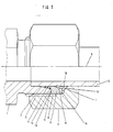
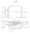
- Figure 1 shows the connection system in the screwed state in a partial side view and in partial longitudinal section.
- the receptacle body or screw connector 1 has a 24 degree cone 2 according to DIN 3861 or ISO 8434 and is provided with an external thread 3 onto which the internal thread 4 of the union nut 5 is screwed during assembly.
- the union nut 5 is also standardized according to DIN 3870 in the present case.
- the two-part ring lying in the assembled state between the union nut and the screw connection consists of the sealing element 6 and the holding element 7, whereby the sealing function is separated from the holding function.
- An elastomer seal 8 is vulcanized in front of the sealing element 6. Instead of the elastomer ring 8, it is also possible to loosely insert an O-ring which seals in the 24 degree cone 2.
- the sealing element 6 bears with its stop surface 10, which extends radially to its ring axis 9, against the ring surface 11 of the receiving body 1.
- a nose 12 extends over part of the inner conical surface (cone 2) of the receiving body 1.
- the sealing element 6 is provided with a conical sliding surface 14 which merges into a stop surface 15 extending radially to the tube axis 9 .
- the sliding surface 14 is optimized as a sliding surface for the holding element 7 which slides on this surface during the assembly process. This can be done by a special polishing or hardening process or by a special coating. This makes it possible to considerably reduce the friction and thus the torque of the union nut to be applied for the assembly process.
- the holding element 7 is designed as a cutting ring with a cutting edge and has a secondary sealing function.
- the holding element or the cutting ring 7 is designed as a spring-elastic element, so that it clamps the tube 13 in the rear part and in this way exerts damping properties.
- the arrangement of the holding element 7 in the rear area, which is assigned to the inner contact surface 16 of the union nut, results in an increased shearing volume in comparison to the known cutting ring screw connections before the incision into the tube jacket 13, which increases security against tearing out the tube.
- FIG. 1 shows the connection system in a state of complete final assembly. This can be recognized by the fact that the axial gap 20 between the stop surface 18 of the holding element 7 and the radial abutment surface 15 of the sealing element 6 is completely closed in the assembled state.
- the holding element 7 is designed as a cutting ring with a cutting edge.
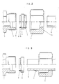
- Figure 2 shows the individual functional elements of the pipe connection before assembly in an exploded view.
- the holding element 7 is already pressed with the sealing element 6 before assembly and the elastomer ring is glued to the sealing element 6 or vulcanized onto the sealing element. This ensures that instead of the three separate elements, only a single functional element is to be handled.
- the tube 13 is guided through the union nut 5, holding element 7, sealing element 6 and elastomer ring 8 into the screw connection piece up to its stop 17.
- the inner contact surface 16 abuts the holding element 7, which abuts the sealing element 6 with its stop surface 10 against the inner ring surface 11.
- the further cutting process is described in more detail with reference to FIG. 10 and the graphic representations 11 and 12.
- connection system is released again after a fixed final assembly, a state results which is described by FIG. 3.
- the holding element 7 is permanently connected to the tube 13, while the sealing element 6 is fully movable and thus interchangeable.
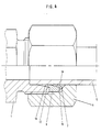
- FIG. 4 shows a further embodiment of the invention in a representation similar to that in FIG. 1.
- the sealing element 6 has on its nose 12 a sealing lip 19 which is pressed onto the cone 2.
- the nose 12 is slightly longer than in the embodiment according to FIG. 1. This results in a clamping effect between the tube 13 and the cone 2.
- the sealing element 6 therefore has no elastomer seal.
- a purely metallic seal is used for this, which is particularly suitable for higher temperatures and aggressive media in which no elastomers can be used.
- the holding element 7 ' is designed as a cutting ring with two cutting edges (progressive ring), which advantageously clamps the tube 13 along the entire length of the cone 14.
- the holding element 7 ′ is deformed in the radial direction by the sliding surface 14 designed as a cone on the sealing element 6 and cuts into the tube 13. Due to the well-known design of the cutting ring as a progressive ring, the holding force is increased considerably, which again gives the connection system a higher pressure capacity.
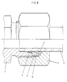
- FIG. 6 shows an exemplary embodiment in which a clamping ring 7 ′′ with two edges is used instead of a cutting ring 7 ′. Because there is no incision in the pipe jacket, the pipe 13 is also deformed in the radial direction. In the rear area, the holding element is clamped by the 45 degree bevel 21 in the standardized union nut 5. The great advantage of this geometric design of the holding element 7 ′′ is that the assembly forces are reduced compared to conventional cutting ring connections.
- FIG. 10 shows an enlarged illustration of the holding element 7 pressed with the sealing element 6.
- the elastomer ring 8 is vulcanized onto the sealing element.
- the cone or the thrust piece of the sliding surface 14 of the sealing element 6 has a cylindrical projection 22 which is smaller than the associated diameter of the holding element 7, so that an interference fit can take place.
- Another possibility is the gluing of the holding element 7 in the cone 14 of the sealing element 6.
- the adhesive is chosen so that it breaks open during assembly and releases a lubricant that wets the sliding surface.
- Another advantage of this preassembly of the individual elements is that the cutting edges of the holding element 7 are protected against external damage by the covering of the sealing element.
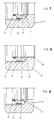
- Figures 7, 8 and 9 show so-called functional nuts 5 'with integrated sealing and holding elements 6 and 7 of the type described above.
- the sealing element 6 is pressed with the holding element 7 and fastened with it in a suitable manner with the union nut 5, so that only a single element in the form of the union nut is to be handled, whereby the assembly is simplified and error possibilities are reduced again.
- One possible connection is to attach a bead 23 made of vulcanized elastomer to the outer diameter of the sealing element 6.
- the bead 23 is jammed in the internal thread of the union nut 5, but this does not hinder the assembly.
- a further possibility of fastening the holding element 7 and thus also the sealing element 6 in the union nut 5 ' can be seen in FIG. 8 and consists in lengthening the holding element 7 in such a way that it is passed through the bottom of the nut and caulked on the outside (edge 24). can be so that it is rotatably held in the mother. When dismantling, the calked edge folds over so that the nut can be pushed back.
- FIG. 9 shows a further possibility of fastening the holding element 7 in the union nut 5. This consists in that the holding element 7 is glued to the nut 5. The adhesive is chosen so that it breaks open during assembly and releases a lubricant that reduces the friction between the nut 5 and the holding element 7.
- FIGS. 11 and 12 show representations of a direct assembly in the connecting piece (FIG. 11) and a final assembly of an already pre-assembled connection (FIG. 12).
- the diagrams show the assembly process for pipe connections, the torque being plotted against the turning path.
- Figure 11 the assembly process of two pipe connections is compared.
- Curve 1 shows the course of a commonly used cutting ring pipe connection. The torque rises continuously from the start of assembly and the installer cannot see a clear end.
- Curve 2 shows the course of the pipe connection system according to the invention.
- the torque rises more weakly at the start of assembly than in the prior art.
- the torque rises very steeply, since in this area the gap 20 between the axial stop surfaces 15 and 18 closes.
- This sharp increase in torque is unmistakable and it shows the installer that the assembly is complete, which prevents over-assembly. In both cases, assembly is complete at the intersection of the curves.
- the area under the curves is a measure of the assembly work performed. The diagram clearly shows that the work done on curve 2 is significantly less.
- the hatched area is the difference between the areas of curve 1 and 2. It represents the labor saving when assembling the pipe fitting according to the invention compared to the prior art.
- FIG. 12 shows the assembly process of a pipe connection which has already been pre-assembled according to the invention and is fully assembled. ⁇ (Curve 1) compared to a known cutting ring connection (curve 2) ⁇ . After a very short, flat rise, the torque rises sharply, since the gap 20 between the axial stop surfaces 15 and 18 is immediately closed when it is reassembled.
- connection system described according to the invention over the known cutting ring connection is u. a. in that, due to the split sealing and holding function, a pre-assembly can be carried out which corresponds to a finished assembly in the sense of the cutting ring screw connection. This ensures that the pipe connection proposed according to the invention, particularly with regard to series assembly, saves a considerable amount of work and time compared to the conventional cutting ring fitting.
Abstract
Description
Die Erfindung betrifft ein Verbindungssystem für höchstdruckfeste Rohrverschraubungen mit einem genormten, einen 24 Grad Anschluß aufweisenden Aufnahmekörper, einer überwurfmutter zur Herstellung einer druckfesten Verbindung, einem Rohr oder einem Anschlußzapfen zum Verbinden anderer Systemkomponenten und einem zweiteiligen Ring, wobei der eine Ring als Schneid- oder Klemmring und der andere als Dichtelement ausgebildet ist.The invention relates to a connection system for extremely pressure-resistant pipe fittings with a standardized, a 24 degree connection receiving body, a union nut for establishing a pressure-resistant connection, a pipe or a connecting pin for connecting other system components and a two-part ring, the one ring as a cutting or clamping ring and the other is designed as a sealing element.
Zur Herstellung eines Verbindungssystems für druckfeste Rohrverschraubungen ist es bekannt, zweiteilige Ringe zu verwenden, welche als Schneid- und/oder Klemmringe wirken. So geht beispielsweise aus der DIN 4000 Teil 36, Ziffer 13, ein Doppelkeilring hervor, welcher aus zwei getrennten Keil- oder Klemmringen besteht, die beim Montagevorgang in sich zeitlich überlappender Weise zur Einwirkung kommen. Hierdurch ist für den Monteur keine eindeutige Feststellung des Montageendes möglich, wodurch Fehlmontagen nicht auszuschließen sind. Es erfordert zumindest eine große Erfahrung des Monteurs über das Kräfteverhalten des Verbindungssystems bei der Montage, um Fehlmontagen zu vermindern oder auszuschließen.To produce a connection system for pressure-resistant pipe fittings, it is known to use two-part rings, which act as cutting and / or clamping rings. For example, from DIN 4000 Part 36,
Aus der DE-PS 12 53 531 ist eine Rohrmuffenverschraubung bekannt, welche zwei hintereinandergeschaltete Quetschringe aufweist, die mittels einer Überwurfmutter zum Eingraben in den Mantel des Rohres, den sie umgeben, gebracht werden. Auch hierbei ergeben sich die oben aufgeführten Probleme bei der Montage, da sich die Kräfte, welche auf die beiden Ringe einwirken, überlappen, wodurch der Montagezustand nicht eindeutig feststellbar ist und erhebliche Montagekräfte erforderlich sind, die bereits zur Überwindung von Reibungskräften aufgebracht werden müssen.From DE-PS 12 53 531 a pipe socket screw connection is known which has two crimp rings connected in series, which are brought into the jacket of the pipe which surrounds them by means of a union nut for digging into them. Here, too, the problems listed above arise during assembly, since the forces acting on the two rings overlap, as a result of which the state of the assembly cannot be clearly determined and considerable assembly forces are required which must already be applied to overcome frictional forces.
Aus der US-A-2687315 ist ein Verbindungssystem zur Herstellung einer Rohrverbindung bekannt, welches mit einem Schneidring und einem metallischen Dichtelement versehen ist. Das Dichtelement weist einen Konus auf, welcher zur Führung des Schneidkopfes des Schneidringes ausgebildet ist. Ein weiteres Zusammenwirken dieser beiden Elemente ist nicht vorgesehen, insbesondere ist keine Aufteilung zwischen der Halte- und Dichtfunktion vorgesehen. Dem Monteur wird kein steiler Kraftanstieg als Zeichen einer fertigen Montage vermittelt.From US-A-2687315 a connection system for producing a pipe connection is known, which is provided with a cutting ring and a metallic sealing element. The sealing element has a cone which is designed to guide the cutting head of the cutting ring. No further interaction of these two elements is provided, in particular no division between the holding and sealing functions is provided. The fitter is not given a steep increase in force as a sign of a finished assembly.
Die Erfindung hat sich die Aufgabe gestellt, diese Nachteile zu vermeiden und ein Verbindungssystem unter Verwendung genormter Verbindungs- und Schraubelemente vorzuschlagen, bei dem die Montagekräfte gegenüber dem Stand der Technik bei genormten Schneidringverbindungen mit 24 Grad Konus erheblich vermindert sind, die Vor- und Fertigmontage von Schneidringverschraubungen und das Fein- und Höchstdruckdichtverhalten im Vergleich zu herkömmlichen Schneidringverbindungen erheblich verbessert wird.The invention has set itself the task of avoiding these disadvantages and proposing a connection system using standardized connecting and screwing elements, in which the assembly forces are considerably reduced compared to the prior art with standardized cutting ring connections with a 24 degree cone, the pre- and final assembly of Cutting ring fittings and the fine and high pressure sealing behavior compared to conventional cutting ring connections is significantly improved.
Die Lösung dieser Aufgabe erfolgt gemäß der Erfindung dadurch, daß bei dem eingangs genannten Verbindungssystem das Dichtelement dem Aufnahmekörper zugeordnet und dem Halteelement vorgelagert ist, und im montierten Zustand mit einer radial zu seiner Ringachse verlaufenden Anschlagfläche an der inneren Ringfläche des Aufnahmekörpers anliegt und sich mindestens über einen Teil der inneren Kegelfläche [Konus] des Aufnahmekörpers erstreckt und für das Halteelement eine konisch verlaufende Gleitfläche und eine radial zur Rohr- oder Ringachse sich erstreckende Anschlagfläche aufweist, wobei das Halteelement eine mit der hinteren Anschlagfläche des Dichtelements im fertig montierten Zustand zusammenwirkende Anschlagfläche aufweist.This object is achieved according to the invention in that, in the connection system mentioned at the outset, the sealing element is assigned to the receiving body and is arranged in front of the holding element, and in the assembled state it bears against the inner annular surface of the receiving body with a stop surface running radially to its ring axis and at least over extends a part of the inner conical surface [cone] of the receiving body and has a conical sliding surface for the holding element and a stop surface extending radially to the pipe or ring axis, the holding element having a stop surface interacting with the rear stop surface of the sealing element in the fully assembled state.
Der Erfindung liegt die Erkenntnis zugrunde, daß die funktionelle Trennung eines zweiteiligen Ringes in ein Halteelement und in ein Dichtelement eine Reihe von Aufgaben löst, da sich durch die funktionelle Trennung die Möglichkeit ergibt, jedes Element für seine Aufgabe maximal auszugestalten, wie im folgenden noch gezeigt wird.The invention is based on the finding that the functional separation of a two-part ring into a holding element and into a sealing element solves a number of tasks, because by the functional separation gives the possibility to maximally design each element for its task, as will be shown in the following.
So ist es vorteilhaft und in einfacher Weise technisch möglich, die Gleitfläche des Dichtelements als Konus auszubilden und seine Oberfläche so zu behandeln, daß die bei der Montage entstehende Reibung zwischen Halte- und Dichtelement verringert wird.Thus, it is advantageous and technically possible in a simple manner to design the sliding surface of the sealing element as a cone and to treat its surface in such a way that the friction between the holding and sealing element that occurs during assembly is reduced.
Nach einer Ausführungsform der Erfindung weist das aus Metall bestehende Dichtelement an dem Teil, der sich mindestens über einen Bereich der inneren Kegelfläche des Aufnahmekörpers erstreckt, eine metallische Dichtlippe auf. Diese Ausführungsform eignet sich besonders für den Einsatz des Verbindungssystems für höhere Temperaturen und für aggressive Medien, wo keine Elastomere einsetzbar sind. Ist ein solcher Einsatz nicht beabsichtigt, so ist dem Dichtelement im montierten Zustand ein Elastomerdichtring vorgelagert, wodurch eine hohe Dichtigkeit erreicht wird.According to one embodiment of the invention, the sealing element made of metal has a metallic sealing lip on the part which extends at least over a region of the inner conical surface of the receiving body. This embodiment is particularly suitable for the use of the connection system for higher temperatures and for aggressive media, where no elastomers can be used. If such an application is not intended, the sealing element is preceded by an elastomer sealing ring in the assembled state, as a result of which a high level of tightness is achieved.
Besonders für Montagezwecke ist es vorteilhaft, den Elastomerdichtring mit dem Dichtelement zu verbinden. Eine solche Verbindung zwischen dem Elastomerdichtring und dem Dichtelement kann durch Anvulkanisierung oder Klebung erfolgen.It is particularly advantageous for assembly purposes to connect the elastomer sealing ring to the sealing element. Such a connection between the elastomer sealing ring and the sealing element can be made by vulcanization or gluing.
Besonders für die Kraftcharakteristik während des Montageverlaufs ist es nach der Erfindung vorteilhaft, daß das Halteelement eine mit der hinteren Anschlagkante des Dichtelements im fertig montierten Zustand zusammenwirkende Anschlagkante aufweist, wie im Zusammenhang mit der Zeichnungsbeschreibung und dem Montageablauf näher erläutert wird.Especially for the force characteristics during the assembly process, it is advantageous according to the invention that the holding element has a stop edge which interacts with the rear stop edge of the sealing element in the fully assembled state, as will be explained in more detail in connection with the drawing description and the assembly process.
In einer weiteren Ausführungsform der Erfindung ist das Halteelement als Schneidring mit zwei Schneiden (Progressivring) ausgebildet, wobei sich die durch den Progressivring ergebenden Vorteile mit denen des Dichtelements vorteilhaft ergänzen.In a further embodiment of the invention, the holding element is designed as a cutting ring with two cutting edges (progressive ring), the advantages resulting from the progressive ring advantageously complementing those of the sealing element.
In einer weiteren Ausführungform der Erfindung ist das Haltelement als Zwei-Kanten-Klemmring ausgebildet.In a further embodiment of the invention, the holding element is designed as a two-edge clamping ring.
Für die Vereinfachung der Handhabung der einzelnen Elemente bei der Montage ist es von Vorteil, das Dichtelement mit dem Halteelement im Anlieferungszustand zu verbinden.To simplify the handling of the individual elements during assembly, it is advantageous to connect the sealing element to the holding element in the delivery state.
Hierdurch wird die Zahl der zu verwendenden Teile gegenüber zweiteiligen Klemmverbindern verringert und eine Fehlmontage durch Vertauschen anders dimensionierter Elemente ausgeschlossen.As a result, the number of parts to be used is reduced compared to two-part clamp connectors and incorrect assembly due to interchanging differently dimensioned elements is excluded.
Die Verbindung der beiden Elemente erfolgt durch Preßpassung oder auch durch Klebung, wobei der Kleber ein bei der Montage freisetzbares Schmiermittel enthält. Durch diese Maßnahme wird ein Schmiermittel zur passenden Zeit in richtiger Menge an die richtige Stelle im Verschraubungssystem gebracht.The connection of the two elements is carried out by a press fit or by gluing, the glue containing a lubricant that can be released during assembly. With this measure, the right amount of lubricant is brought to the right place in the screw system at the right time.
Eine weitere Maßnahme nach der Erfindung zur Verringerung der Teilezahl für die Montage besteht darin, daß am Außendurchmesser des Dichtelements eine durchgehende oder unterbrochene Wulst aus einem vulkanisierten Elastomer aufgetragen ist. Hierdurch ist es möglich, den zweiteiligen Ring mit seinem Dichtungsring in der Überwurfmutter vormontiert unterzubringen. Eine solche Vormontage kann fabrikmäßig erfolgen, so daß Montagefehler durch Verwechselungen ausgeschlossen sind und die Montagezeit erheblich verkürzt wird.Another measure according to the invention for reducing the number of parts for assembly is that a continuous or interrupted bead made of a vulcanized elastomer is applied to the outer diameter of the sealing element. This makes it possible to accommodate the two-part ring with its sealing ring pre-assembled in the union nut. Such pre-assembly can be carried out in the factory, so that assembly errors due to mix-ups are excluded and the assembly time is considerably reduced.
Die Verbindung des zweiteiligen Ringes mit der Überwurfmutter kann nach einer weiteren Ausführungsform auch dadurch erfolgen, daß das Haltelement mit einer Verlängerung versehen ist, die sich durch den Boden der Überwurfmutter erstreckt und am äußeren Ende mit der Überwurfmutter verklemmt ist.According to a further embodiment, the connection of the two-part ring to the union nut can also take place in that the retaining element is provided with an extension which extends through the bottom of the union nut and is clamped to the union nut at the outer end.
Weitere Verbindungsmöglichkeiten ergeben sich dadurch, daß das Halteelement mit der Mutter verklebt ist, wobei der Kleber ein bei der Montage freisetzbares Schmiermittel enthält.Further connection options result from the fact that the holding element is glued to the nut, the adhesive containing a lubricant which can be released during assembly.
Die Erfindung wird anhand der Zeichnungen näher beschrieben. Hierbei zeigen:
FIGUR 1- einen Teillängsschnitt und eine Teilansicht eines Verbindungssystems im montierten Zustand mit einem elastomeren Dichtsegment;
FIGUR 2- eine Explosionsdarstellung der einzelnen Verbindungselemente vor der Montage;
FIGUR 3- eine Explosionsdarstellung nach der Montage und erfolgter Demontage;
- FIGUR 4
- einen Teillängsschnitt und eine Teilansicht eines Verbindungssystems im montierten Zustand nach
Figur 1, jedoch mit einer metallischen Ausführungsform eines Dichtelements; FIGUR 5- einen Teillängsschnitt und eine Teilansicht eines Verbindungssystems im montierten Zustand nach
Figur 1, mit einer Ausführungsform eines Halteelements als Progressivring; FIGUR 6- einen Teillängsschnitt und eine Teilansicht eines Verbindungssystems im montierten Zustand nach
Figur 1, mit einer Ausführungsform eines Halteelements als Zei-Kanten Klemmring; FIGUR 7- einen Teilschnitt einer Überwurfmutter mit integriertem zweiteiligen Ring und einer Wulst zur Zentrierung und Befestigung im Anlieferungszustand;
FIGUR 8- einen Teilschnitt einer Überwurfmutter mit integriertem zweiteiligem Ring und einem verlängerten Halteelement zur Zentrierung und Befestigung im Anlieferungszustand;
FIGUR 9- einen Teilschnitt einer Überwurfmutter mit integriertem zweiteiligem Ring und einem mit der Überwurfmutter verklebtem Halteelement zur Zentrierung und Befestigung im Anlieferungszustand;
FIGUR 10- einen Längsschnitt eines zweiteiligen Ringes im Preßsitz mit anvulkanisiertem Elastomerring;
FIGUR 11- eine graphische Darstellung einer Direktmontage und
FIGUR 12- eine graphische Darstellung einer Fertigmontage.
- FIGURE 1
- a partial longitudinal section and a partial view of a connection system in the assembled state with an elastomeric sealing segment;
- FIGURE 2
- an exploded view of the individual fasteners before assembly;
- FIGURE 3
- an exploded view after assembly and disassembly;
- FIGURE 4
- a partial longitudinal section and a partial view of a connection system in the assembled state according to Figure 1, but with a metallic embodiment of a sealing element;
- FIGURE 5
- a partial longitudinal section and a partial view of a connection system in the assembled state according to Figure 1, with an embodiment of a holding element as a progressive ring;
- FIGURE 6
- a partial longitudinal section and a partial view of a connection system in the assembled state according to Figure 1, with an embodiment of a holding element as a time-edge clamping ring;
- FIGURE 7
- a partial section of a union nut with an integrated two-part ring and a bead for centering and fastening in the delivery state;
- FIGURE 8
- a partial section of a union nut with an integrated two-part ring and an extended holding element for centering and fastening in the delivery state;
- FIGURE 9
- a partial section of a union nut with an integrated two-part ring and a holding element glued to the union nut for centering and fastening in the delivery state;
- FIGURE 10
- a longitudinal section of a two-part ring in a press fit with vulcanized elastomer ring;
- FIGURE 11
- a graphic representation of a direct assembly and
- FIGURE 12
- a graphic representation of a final assembly.
Die Figur 1 zeigt das Verbindungssystem im verschraubten Zustand in einer Teilseitenansicht und im Teillängsschnitt.Figure 1 shows the connection system in the screwed state in a partial side view and in partial longitudinal section.
Der Aufnahmekörper oder Verschraubungsstutzen 1 weist einen 24 Grad Konus 2 nach DIN 3861 bzw. ISO 8434 auf und ist mit einem Außengewinde 3 versehen, auf das das Innengewinde 4 der Überwurfmutter 5 bei der Montage geschraubt wird. Auch die Überwurfmutter 5 ist im vorliegenden Fall nach DIN 3870 genormt.The receptacle body or screw
Der im montierten Zustand zwischen der Überwurfmutter und dem Verschraubungsstutzen liegende zweiteilige Ring besteht aus dem Dichtelement 6 und dem Halteelement 7, wodurch die Dichtfunktion von der Haltefunktion getrennt wird. Vor dem Dichtelement 6 ist eine Elastomerdichtung 8 anvulkanisiert. Es ist auch möglich anstelle des Elastomerringes 8 einen O-Ring lose einzulegen, welcher im 24 Grad Konus 2 dichtet.The two-part ring lying in the assembled state between the union nut and the screw connection consists of the sealing
Das Dichtelement 6 liegt in dem dargestellten montierten Zustand mit seiner radial zu seiner Ringachse 9 verlaufenden Anschlagfläche 10 an der Ringfläche 11 des Aufnahmekörpers 1 an. Eine Nase 12 erstreckt sich über einen Teil der inneren Kegelfläche (Konus 2) des Aufnahmekörpers 1. Auf seiner der Rohrwandung 13 zugekehrten Seite ist das Dichtelement 6 mit einer konisch verlaufenden Gleitfläche 14 versehen, die in eine radial zur Rohrachse 9 sich erstreckende Anschlagfläche 15 übergeht.In the assembled state shown, the sealing
Die Gleitfläche 14 ist als Gleitfläche für das Halteelement 7, das während des Montagevorganges auf dieser Fläche gleitet, optimiert. Dies kann durch einen besonderen Polier- oder Härtevorgang oder durch eine spezielle Beschichtung erfolgen. Hierdurch ist es möglich die Reibung und damit das für den Montagevorgang aufzubringende Drehmoment der Überwurfmutter erheblich zu reduzieren.The sliding
Bei den bekannten Schneidringverschraubungen kann eine Optimierung der Konusfläche nur durch Behandlung des ganzen Verschraubungsstutzens oder durch eine kostenintensive partielle Behandlung der Konen erreicht werden.In the known cutting ring screw connections, an optimization of the cone surface can only be achieved by treating the entire screw connection piece or by costly partial treatment of the cones.
Das Halteelement 7 ist bei diesem Ausführungsbeispiel als Schneidring mit einer Schneide ausgebildet und übt eine sekundäre Dichtfunktion aus.In this exemplary embodiment, the holding
Das Halteelement bzw. der Schneidring 7 ist als federelastisches Element ausgelegt, so daß er im hinteren Teil das Rohr 13 beklemmt und auf diese Weise Dämpfungseigenschaften ausübt. Durch die Anordnung des Halteelementes 7 im hinteren, der inneren Kontaktfläche 16 der Überwurfmutter zugeordneten Bereich, ergibt sich im Vergleich zu den bekannten Schneidringverschraubungen ein vergrößertes Abschervolumen vor dem Einschnitt in den Rohrmantel 13, wodurch eine erhöhte Sicherheit gegen ein Herausreißen des Rohres erreicht wird.The holding element or the
Die Figur 1 zeigt das Verbindungssystem in einem Zustand der vollständigen Endmontage. Dies ist daran er-kennbar, daß der axiale Spalt 20 zwischen der Anschlagfläche 18 des Halteelements 7 und der radialen Stoßfläche 15 des Dicht- elements 6 im montierten Zustand ganz geschlossen ist.FIG. 1 shows the connection system in a state of complete final assembly. This can be recognized by the fact that the
Durch eine entsprechende Auslegung der axialen Anschlagflächen 18 und 15 steigt das Drehmoment am Ende der vorschriftsmäßigen Montage steil an, wodurch eine Übermontage wirksam verhindert wird (Blockmontage).By appropriate design of the axial stop surfaces 18 and 15, the torque rises steeply at the end of the correct assembly, thereby effectively preventing over-assembly (block assembly).
Damit ist eine optische Montagekontrolle ohne zusätzliche Werkzeuge möglich. Wenn der Spalt 20 zwischen Dicht- und Halteelement 6 und 7 geschlossen ist, ist die Montage funktionssicher abgeschlossen und für höchstdruckbeanspruchte Verbindungen brauchbar. Bei diesem Ausführungsbeispiel ist das Halteelement 7 als Schneidring mit einer Schneide ausgebildet.This enables an optical assembly inspection without additional tools. If the
Dem Monteur wird hierdurch eine klare optische Überprüfbarkeit seiner Montage ermöglicht.This enables the installer to clearly check his assembly visually.
Die Figur 2 zeigt die einzelen Funktionselemente der Rohrverbindung vor der Montage in einer Explosionsdarstellung.Figure 2 shows the individual functional elements of the pipe connection before assembly in an exploded view.
Hierbei ist das Halteelement 7 mit dem Dichtelement 6 bereits vor der Montage verpreßt und der Elastomerring ist mit dem Dichtelement 6 verklebt oder an das Dichtelement anvulkanisiert. Hierdurch wird erreicht, daß anstelle der drei getrennten Elemente nur ein einziges Funktionselement zu handhaben ist. Für die Montage wird das Rohr 13 durch die Überwurfmutter 5, Halteelement 7, Dichtelement 6 und Elastomerring 8 in den Verschraubungsstutzen bis zu seinem Anschlag 17 geführt. Wird die Überwurfmutter 5 angezogen, so stößt die innere Kontaktfläche 16 gegen das Halteelement 7, welches das Dichtelement 6 mit seiner Anschlagfläche 10 gegen die innere Ringfläche 11 stößt. Der weitere Einschneidvorgang wird anhand der Figur 10 und den graphischen Darstellungen 11 und 12 genauer beschrieben.Here, the holding
Wird das Verbindungssystem nach einer festen Endmontage wieder gelöst, so ergibt sich ein Zustand, welcher durch die Figur 3 beschrieben wird.If the connection system is released again after a fixed final assembly, a state results which is described by FIG. 3.
Nach dem Lösen der montierten Verschraubung ist das Halteelement 7 unlösbar mit dem Rohr 13 verbunden, während das Dichtelement 6 voll beweglich und somit austauschbar ist.After loosening the assembled screw connection, the holding
Die Figur 4 zeigt eine weitere Ausführungsform der Erfindung in einer ähnlichen Darstellung wie in Figur 1. Das Dichtelement 6 weist an seiner Nase 12 eine Dichtlippe 19 auf, die auf den Konus 2 gepreßt wird. Um dies zu erreichen, ist die Nase 12 geringfügig länger als bei der Ausführungsform nach Figur 1 ausgebildet. Dadurch erfolgt eine Klemmwirkung zwischen Rohr 13 und Konus 2. Das Dichtelement 6 weist daher keine Elastomerdichtung auf. Es erfolgt dafür eine rein metallische Dichtung, welche für höhere Temperaturen und aggressive Medien besonders geeignet ist, bei denen keine Elastomere einsetzbar sind.FIG. 4 shows a further embodiment of the invention in a representation similar to that in FIG. 1. The sealing
In dem weiteren Ausführungsbeispiel nach Figur 5 ist das Halteelement 7' als ein Schneidring mit zwei Schneiden (Progressivring) ausgebildet, der in vorteilhafter Weise das Rohr 13 auf der gesamten Länge des Konus 14 verklemmt. Das Halteelement 7' wird durch die als Konus am Dichtelement 6 ausgebildete Gleitfläche 14 bei der Montage in radialer Richtung verformt und schneidet in das Rohr 13 ein. Durch die an sich bekannte Ausbildungsform des Schneidringes als Progressivring wird die Haltekraft erheblich erhöht, wodurch nochmals eine höhere Druckbelastbarkeit des Verbindungssystems gegeben ist.In the further exemplary embodiment according to FIG. 5, the holding element 7 'is designed as a cutting ring with two cutting edges (progressive ring), which advantageously clamps the
Figur 6 zeigt ein Ausführungsbeispiel, bei dem anstelle eines Schneidringes 7'ein Klemmring 7'' mit zwei Kanten verwendet wird. Weil kein Einschnitt in den Rohrmantel erfolgt, wird das Rohr 13 ebenfalls in radialer Richtung verformt. Im hinteren Bereich erfolgt die Klemmung des Halteelementes durch die 45 Grad Schräge 21 in der genormten Überwurfmutter 5. Der große Vorteil dieser geometrischen Ausbildung des Halteelementes 7'' sind die 2gegenüber herkömmlichen Scheidringverbindungen reduzierten Montagekräfte.FIG. 6 shows an exemplary embodiment in which a
Die Figur 10 zeigt eine vergrößerte Darstellung des mit dem Dichtelement 6 verpreßten Halteelements 7. Der Elastomerring 8 ist auf das Dichtelement aufvulkanisiert.FIG. 10 shows an enlarged illustration of the holding
Der Konus bzw. das Anlaufstück der Gleitfläche 14 des Dichtelements 6 weist einen zylindrischen Ansatz 22 auf, der kleiner als der zugehörige Durchmesser des Halteelementes 7 ist, so daß eine Preßpassung erfolgen kann.The cone or the thrust piece of the sliding
Eine weitere Möglichkeit ist das Verkleben des Halteelementes 7 im Konus 14 des Dichtelements 6. Der Kleber ist so gewählt, daß er während der Montage aufbricht und ein Schmiermittel freigibt, daß die Gleitfläche benetzt.Another possibility is the gluing of the holding
Ein weiterer Vorteil dieser Vormontage der einzelnen Elemente besteht darin, daß die Schneidkanten des Halteelements 7 gegen äußere Beschädigungen durch die Überdeckung des Dichtelements geschützt werden.Another advantage of this preassembly of the individual elements is that the cutting edges of the holding
Die Figuren 7, 8 und 9 zeigen sogenannte Funktionsmuttern 5' mit integrierten Dicht- und Halteelementen 6 und 7 der zuvor beschriebenen Art.Figures 7, 8 and 9 show so-called functional nuts 5 'with integrated sealing and holding
In allen drei Fällen ist das Dichtelement 6 mit dem Halteelement 7 verpreßt und mit diesem in geeigneter Weise mit der Überwurfmutter 5 befestigt, so daß nur ein einziges Element in Form der Überwurfmutter zu handhaben ist, wodurch die Montage vereinfacht wird und Fehlermöglichkeiten nochmals verringert werden.In all three cases, the sealing
Eine Möglichkeit der Verbindung besteht darin, einen Wulst 23 aus vulkanisiertem Elastomer am Außendurchmesser des Dichtelementes 6 anzubringen. Der Wulst 23 verklemmt sich im Innengewinde der Überwurfmutter 5, wodurch die Montage jedoch nicht behindert wird.One possible connection is to attach a
Eine weitere Möglichkeit der Befestigung des Halteelements 7 und damit auch des Dichtelements 6 in der Überwurfmutter 5' geht aus Figur 8 hervor und besteht darin, das Halteelement 7 derart zu verlängern, daß es durch den Boden der Mutter durchgeführt und außen verstemmt (Kante 24) werden kann, so daß es in der Mutter drehbar festgehalten wird. Bei der Demontage legt sich die verstemmte Kante um, so daß ein zurückschieben der Mutter gewährleistet ist.A further possibility of fastening the holding
Die Figur 9 zeigt eine weitere Möglichkeit der Befestigung des Halteelements 7 in der Überwurfmutter 5. Diese besteht darin, daß das Halteelement 7 mit der Mutter 5 verklebt wird. Der Kleber wird dabei so gewählt, daß er während der Montage aufbricht und ein Schmiermittel freigibt, daß die Reibung zwischen Mutter 5 und Halteelement 7 verringert.FIG. 9 shows a further possibility of fastening the holding
In allen diesen Fällen ergibt sich der große Vorteil, daß bei der Montage nur noch eine Funktionsmutter gehandhabt werden muß.In all of these cases there is the great advantage that only one functional nut has to be handled during assembly.
Die Figuren 11 und 12 geben Darstellungen einer Direktmontage im Verbindungsstutzen (Figur 11) und einer Fertigmontage einer bereits vormontierten Verbindung (Figur 12) wieder.FIGS. 11 and 12 show representations of a direct assembly in the connecting piece (FIG. 11) and a final assembly of an already pre-assembled connection (FIG. 12).
Die Diagramme stellen den Montageverlauf von Rohrverbindungen dar, wobei das Drehmoment über dem Drehweg aufgetragen ist. In Figur 11 wird der Montageverlauf zweier Rohrverbindungen verglichen. Hierbei zeigt die Kurve 1 den Verlauf einer allgemein gebräuchlichen Schneidring-Rohrverbindung. Das Drehmoment steigt von Beginn der Montage kontinierlich an und ein deutliches Ende ist für den Monteur nicht erkennbar.The diagrams show the assembly process for pipe connections, the torque being plotted against the turning path. In Figure 11 the assembly process of two pipe connections is compared.
Die Kurve 2 gibt den Verlauf der Rohrverbindungssystems nach der Erfindung wieder. Hierbei steigt das Drehmoment zu Beginn der Montage schwächer als beim Stand der Technik an. Zum Ende der Montage steigt das Drehmoment sehr steil an, da in diesem Bereich der Spalt 20 zwischen den axialen Anschlagflächen 15 und 18 sich schließt. Dieser starke Anstieg des Drehmoments ist unverkennbar und er zeigt dem Monteur das vollständige Ende der Montage an, wodurch Übermontagen verhindert werden. Am Kreuzungspunkt der Kurven ist die Montage in beiden Fällen beendet. Die Fläche unter den Kurven ist jeweils ein Maß für die geleistete Montagearbeit. Das Diagramm zeigt deutlich, daß die geleistete Arbeit bei der Kurve 2 deutlich geringer ist. Die schraffierte Fläche ist die Differenz der Flächen der Kurve 1 und 2. Sie stellt die Arbeitsersparnis bei der Montage der Rohrverschraubung gemäß der Erfindung gegenüber dem Stand der Technik dar.
Die Figur 12 zeigt den Montageverlauf einer bereits gemäß der Erfindung vormontierten Rohrverbindung, die fertig montiert wird. {(Kurve 1) im Vergleich zu einer bekannten Schneidringverbindung (Kurve 2)}. Nach sehr kurzem, flachen Anstieg steigt das Drehmoment stark an, da der Spalt 20 zwischen den axialen Anschlagflächen 15 und 18 bei der erneuten Montage sofort geschlossen wird.FIG. 12 shows the assembly process of a pipe connection which has already been pre-assembled according to the invention and is fully assembled. {(Curve 1) compared to a known cutting ring connection (curve 2)}. After a very short, flat rise, the torque rises sharply, since the
Der große Vorteil des nach der Erfindung beschriebenen Verbindungssystems gegenüber der bekannten Schneidringverbindung besteht u. a. darin, daß aufgrund der aufgeteilten Dicht- und Haltefunktion eine Vormontage durchgeführt werden kann, die einer im Sinne der Schneidringverschraubung fertigen Montage entspricht. Hierdurch wird erreicht, daß durch die gemäß der Erfindung vorgeschlagene Rohrverbindung, besonders im Hinblick auf Serienmontagen, eine erhebliche Arbeits- und Zeitersparnis gegenüber der herkömmlichen Schneidringverschraubung erzielt wird.The great advantage of the connection system described according to the invention over the known cutting ring connection is u. a. in that, due to the split sealing and holding function, a pre-assembly can be carried out which corresponds to a finished assembly in the sense of the cutting ring screw connection. This ensures that the pipe connection proposed according to the invention, particularly with regard to series assembly, saves a considerable amount of work and time compared to the conventional cutting ring fitting.
Zur Verdeutlichung dieses Sachverhalts zeigt die Fläche
- A. die zu leistende Arbeit für die Fertigmontage der vorgeschlagenen Rohrverschraubung nach der Erfindung und
- B. die zu leistende Arbeit für die Fertigmontage einer herkömmlichen Schneidringverschraubung.
- A. the work to be done for the final assembly of the proposed pipe fitting according to the invention and
- B. the work to be done for the final assembly of a conventional cutting ring fitting.

Claims (16)
- A jointing system for high pressure pipe screw joints with a mating part having a standardised 24° connection, a slip-on nut for making a pressure-resistant connection, a pipe or connecting pin for joining other system components and a two-part ring, in which one ring is a cutting or clamp ring and the other ring is a sealing element, characterised in that the sealing element (6) is behind the mating part (1) and the retaining element (7) and in the assembled state lies with its abutment surface (10) running radially to its ring axis (9) against the inner ring surface (11) of the mating part (1) and extends over at least a part of the inner conical surface (2) of the mating part (1) and has a slide surface (14) running conically and a stop surface (15) extending radially to the pipe or ring axis (9), wherein the retaining element (7) has a stop surface (18) co-operating with the rear stop surface (15) of the sealing element (6) in the finished assembled state.
- A jointing system in accordance with claim 2, characterised in that the slide surface (14) of the sealing element (6) is a cone, its upper surface having been treated.
- A jointing system in accordance with claim 1 or 2, characterised in that the part of the metal sealing element (6) that extends along at least one section of the inner chamfered surface (2) of the mating part (1) has a metal sealing lip (19).
- A jointing system in accordance with claim 1 or 2, characterised in that in the assembled state, the sealing element (6) has in front of it an elastomer sealing ring (8).
- A jointing system in accordance with claim 4, characterised in that the elastomer sealing ring (8) is joined to the sealing element (6).
- A jointing system in accordance with claim 5, characterised in that the elastomer sealing ring (8) is jointed with the sealing element (6) by vulcanisation or bonding.
- A jointing system in accordance with one of the previous claims, characterised in that the retaining element (7) is a cutting ring with two cutters, i.e. a progressive ring.
- A jointing system in accordance with one of claims 1 to 6, characterised in that the retaining element (7) is a double-edged clamp ring.
- A jointing system in accordance with one of the previous claims, characterised in that the sealing element (6) is joined to the retaining element (7) when ready to be supplied onwards.
- A jointing system in accordance with claim 9, characterised in that the two elements (6, 7) are joined by press fitting.
- A jointing system in accordance with claim 9, characterised in that the two elements (6, 7) are joined by bonding, wherein the adhesive releases a lubricant during fitting.
- A jointing system in accordance with one of the previous claims, characterised in that a continuous or broken pad (23) made from a vulcanised elastomer is fitted onto the outer diameter of the sealing element (6).
- A jointing system in accordance with one of the previous claims, characterised in that the two-part ring (6, 7) or retaining element (7) is joined to the slip-on nut (5) when ready for onward supply.
- A jointing system in accordance with claim 13, characterised in that the retaining element (7) has an extension, which protrudes through the floor of the slip-on nut (5) and is clamped to the slip-on nut, e.g. by means of an edge (24) at the outer end.
- A jointing system in accordance with claim 13, characterised in that the retaining element (7) is bonded with the nut (5) with an adhesive that releases lubricant during fitting.
- A jointing system in accordance with the previous claims, characterised in that once they have been fitted, the sealing element (6) and the retaining element (7) may be separated from each other without the use of additional means.
Applications Claiming Priority (2)
| Application Number | Priority Date | Filing Date | Title |
|---|---|---|---|
| DE4038539 | 1990-12-03 | ||
| DE4038539A DE4038539C1 (en) | 1990-12-03 | 1990-12-03 |
Publications (2)
| Publication Number | Publication Date |
|---|---|
| EP0489289A1 EP0489289A1 (en) | 1992-06-10 |
| EP0489289B1 true EP0489289B1 (en) | 1994-05-04 |
Family
ID=6419503
Family Applications (1)
| Application Number | Title | Priority Date | Filing Date |
|---|---|---|---|
| EP91119455A Expired - Lifetime EP0489289B1 (en) | 1990-12-03 | 1991-11-14 | Connection system |
Country Status (7)
| Country | Link |
|---|---|
| US (1) | US5351998A (en) |
| EP (1) | EP0489289B1 (en) |
| JP (1) | JP2799797B2 (en) |
| AT (1) | ATE105387T1 (en) |
| DE (2) | DE4038539C1 (en) |
| DK (1) | DK0489289T3 (en) |
| ES (1) | ES2057718T3 (en) |
Families Citing this family (70)
| Publication number | Priority date | Publication date | Assignee | Title |
|---|---|---|---|---|
| DE4116610C2 (en) * | 1991-05-22 | 1996-08-01 | Parker Hannifin Gmbh Geschaeft | System and method for connecting pipelines |
| GB2258895B (en) * | 1991-08-17 | 1994-10-19 | Lucas Ind Plc | Pipe coupling |
| FR2685754A1 (en) * | 1991-12-26 | 1993-07-02 | Legris Sa | Connection device for components of a fluid-distribution network (main), network and components applying it |
| ATE141395T1 (en) * | 1991-12-26 | 1996-08-15 | Legris Sa | CONNECTING DEVICE FOR PARTS OF A FLUID DISTRIBUTION SYSTEM, SAID PARTS AND SYSTEM |
| DE69418701T2 (en) * | 1993-07-20 | 1999-09-30 | Philmac Pty Ltd | COUPLING ATTACKING THE EXTERNAL SURFACE OF A POLYMER TUBE |
| DE19530089C2 (en) * | 1995-08-16 | 2000-06-15 | Manfred Froehlich | High pressure connection system |
| CH691359A5 (en) * | 1995-10-12 | 2001-07-13 | Bucher Guyer Ag | Drainage for a press for separating liquids from solids. |
| DE19637129C2 (en) * | 1995-10-30 | 1999-01-28 | Walterscheid Gmbh Jean | Connection for connecting pipes to a connecting body |
| US5853203A (en) * | 1996-03-13 | 1998-12-29 | Epic Technical Group, Inc. | Barbed tubular connectors |
| DE69805276T2 (en) * | 1997-01-23 | 2002-08-29 | Swagelok Co | PHASE-CONTROLLED STEP-BY-STEP PIPE COUPLING |
| US5882050A (en) | 1997-04-15 | 1999-03-16 | Williams; Peter C. | Ferrule with relief to reduce galling |
| TW473600B (en) | 1997-04-15 | 2002-01-21 | Swagelok Co | Tube fitting, rear ferrule for a two ferrule tube fitting and ferrule for a tube fitting and a non-flared tube fitting |
| US7614668B1 (en) * | 1997-04-15 | 2009-11-10 | Swagelok Company | Ferrule with plural inner diameters |
| US6629708B2 (en) | 1997-04-15 | 2003-10-07 | Swagelok Company | Ferrule with relief to reduce galling |
| DE19742917C2 (en) * | 1997-09-29 | 2002-11-14 | Walterscheid Gmbh Jean | Screw connection with support ring |
| IL121997A (en) * | 1997-10-19 | 2000-06-01 | Plasson Ltd | Pipe coupling |
| JP3076981B2 (en) * | 1997-11-10 | 2000-08-14 | 株式会社ソーラー技研 | Pipe fittings |
| DE10011146A1 (en) * | 2000-03-07 | 2001-09-27 | Parker Hannifin Gmbh | Pipe connection system comprises connector, union nut and compression ring which is locked into a conical bore in the connector by union nut, face of ring which faces nut having reinforcement consisting of narrow sections of ring |
| DE10056236A1 (en) * | 2000-11-13 | 2002-06-06 | Parker Hannifin Gmbh | Cutting ring fittings |
| JP4567214B2 (en) * | 2001-02-02 | 2010-10-20 | 株式会社ベンカン・ジャパン | Pipe fitting |
| US7407196B2 (en) | 2003-08-06 | 2008-08-05 | Swagelok Company | Tube fitting with separable tube gripping device |
| BR0207035A (en) | 2001-02-06 | 2005-02-09 | Swagelok Co | Pipe fitting for stainless steel pipe |
| US7416225B2 (en) | 2001-02-06 | 2008-08-26 | Swagelok Company | Fitting for metal pipe and tubing |
| US7014222B1 (en) * | 2001-03-05 | 2006-03-21 | Rheodyne, Llc | Tube connection system |
| US6851729B2 (en) | 2001-12-07 | 2005-02-08 | Parker-Hannifin Corporation | Tube fitting for medium pressure applications |
| JP2004043845A (en) * | 2002-07-09 | 2004-02-12 | Nippon Steel Corp | Fluid part |
| JP4058733B2 (en) * | 2002-07-09 | 2008-03-12 | 新日鐵住金ステンレス株式会社 | Pipe fitting |
| JP2004043844A (en) * | 2002-07-09 | 2004-02-12 | Nippon Steel Corp | Fluid part |
| US20040061333A1 (en) * | 2002-09-30 | 2004-04-01 | Chu Henry C. | Conduit coupling |
| DE10251204A1 (en) * | 2002-10-31 | 2004-05-19 | Eifeler Maschinenbau Gmbh | Two-part cutting ring, cutting ring set and pipe connection |
| DE20300901U1 (en) * | 2003-01-20 | 2004-01-08 | Endress + Hauser Gmbh + Co. Kg | Fastening system for a measuring device for monitoring and / or determining a fill level |
| US20050194785A1 (en) * | 2003-10-03 | 2005-09-08 | Sami Shemtov | Rain tight compression fitting coupling device |
| US20080007050A1 (en) * | 2003-11-03 | 2008-01-10 | Williams Peter C | Fitting for metal pipe and tubing |
| EP1682805A1 (en) | 2003-11-03 | 2006-07-26 | Swagelok Company | Fitting for metal pipe and tubing |
| CN1902425A (en) * | 2003-11-03 | 2007-01-24 | 斯瓦戈洛克公司 | Fitting for metal pipe and tubing |
| FR2865789B1 (en) * | 2004-02-04 | 2006-03-10 | Legris Sa | INSTANT COUPLING COUPLING |
| CA2459637C (en) * | 2004-02-27 | 2010-04-27 | Masco Canada Limited | Pipe coupling |
| US7497483B2 (en) | 2004-04-22 | 2009-03-03 | Swagelok Company | Fitting for tube and pipe with cartridge |
| TW200602577A (en) * | 2004-04-22 | 2006-01-16 | Swagelok Co | Fitting for tube and pipe |
| US20050244216A1 (en) * | 2004-04-29 | 2005-11-03 | Michael Magraw | Coupler |
| MX2007002145A (en) * | 2004-07-21 | 2007-09-14 | Parker Hannifin Corp | Adaptor and method for converting standard tube fitting/port to push-to-connect tube fitting/port. |
| US8240719B2 (en) | 2004-07-21 | 2012-08-14 | Parker-Hannifin Corporation | Adaptor and method for converting standard tube fitting/port to push-to-connect tube fitting/port |
| DE102005006798A1 (en) * | 2005-02-14 | 2006-08-24 | Eaton Fluid Connectors Gmbh | joint assembly |
| GB2466098B (en) * | 2005-02-25 | 2010-12-15 | Parker Hannifin Plc | A coupling |
| DE102006012493B3 (en) * | 2006-03-16 | 2007-06-14 | Eaton Fluid Connectors Gmbh | Connecting assembly for connecting pipe, has connecting element, with conical bore, which tapers starting from face, and has a longitudinal axis, union nut, which can be screwed onto thread of connecting element |
| US20080001405A1 (en) * | 2006-06-30 | 2008-01-03 | Anna Kui Gey | Plastic-lined metallic pipe for conveying drinking-water and the connectors for the same |
| US20080143105A1 (en) * | 2006-09-22 | 2008-06-19 | Eaton Corporation | Fluid coupling |
| KR20090091735A (en) | 2006-11-02 | 2009-08-28 | 스와겔로크 컴패니 | Pull-up by torque fitting |
| CN1987187B (en) | 2006-12-11 | 2010-04-14 | 浙江华夏阀门有限公司 | Single and double hoop coenosarc extruded connecting pipe joint |
| US20080143107A1 (en) * | 2006-12-13 | 2008-06-19 | Bowling Bruce A | Fluid interconnect assembly |
| US7806443B1 (en) | 2007-03-16 | 2010-10-05 | Plattner Wesley M | Method and apparatus for connecting air conditioning coolant lines |
| US7900974B1 (en) | 2007-03-16 | 2011-03-08 | Plattner Wesley M | Method and apparatus for connecting air conditioning coolant lines |
| KR101377807B1 (en) * | 2007-06-18 | 2014-04-01 | 바이드만 리미티드 | Connecting arrangement for a pipe union |
| EP2162662B9 (en) * | 2007-06-18 | 2012-08-22 | Weidmann LTD. | Connecting arrangement for a pipe union |
| JP2010535989A (en) | 2007-08-03 | 2010-11-25 | スウエイジロク・カンパニー | Lifting ferrule fitting by torque |
| US10215315B2 (en) | 2008-09-05 | 2019-02-26 | Parker-Hannifin Corporation | Tube compression fitting and flared fitting used with connection body and method of making same |
| ITMI20081885A1 (en) * | 2008-10-24 | 2010-04-25 | Olab Srl | UNIVERSAL FITTING FOR HIGH PRESSURES FOR PNEUMATIC, HYDRAULIC AND HYDRAULIC USE. |
| KR102048647B1 (en) | 2008-12-10 | 2019-11-25 | 스와겔로크 컴패니 | Ferrule assembly for conduit fitting |
| US20110115220A1 (en) * | 2009-11-19 | 2011-05-19 | Kuang Ming Kuo | Tube coupling device |
| WO2011091008A1 (en) | 2010-01-21 | 2011-07-28 | Swagelok Company | Conduit gripping device having retaining structure for conduit fitting |
| CN102330723A (en) * | 2010-07-13 | 2012-01-25 | 新秩序投资119股份有限公司 | Pipe fitting |
| US8356843B2 (en) | 2010-09-27 | 2013-01-22 | Hamilton Sundstrand Corporation | Refrigeration system connection fitting |
| BR112013025155A2 (en) | 2011-04-01 | 2017-10-17 | Parker Hannifin Mfg Germany Gmbh & Co Kg | high pressure resistant threaded connection for pipe lines or hoses with a tapered thread |
| ITMI20110603A1 (en) * | 2011-04-11 | 2012-10-12 | Effebi Spa | PIPE FITTING AND RELATED CONNECTION METHOD |
| US20150069753A1 (en) * | 2013-09-10 | 2015-03-12 | Maroko Limited | Advancements in mechanical sealing apparatus |
| WO2015171998A2 (en) | 2014-05-09 | 2015-11-12 | Swagelok Company | Conduit fitting with components adapted for facilitating assembly |
| WO2015187958A1 (en) | 2014-06-04 | 2015-12-10 | Parker-Hannifin Corporation | Compression fitting with torque nut |
| US10584814B2 (en) | 2016-03-23 | 2020-03-10 | Swagelok Company | Conduit fitting with stroke resisting features |
| US11703165B2 (en) | 2018-04-27 | 2023-07-18 | Swagelok Company | Ferrule assembly for conduit fitting |
| US20220341520A1 (en) * | 2021-04-21 | 2022-10-27 | Mueller International, Llc | Wide range pipe fitting |
Family Cites Families (29)
| Publication number | Priority date | Publication date | Assignee | Title |
|---|---|---|---|---|
| US2484815A (en) * | 1947-08-15 | 1949-10-18 | Crawford Fitting Co | Tube coupling |
| US2687315A (en) * | 1949-11-23 | 1954-08-24 | Weatherhead Co | Short coupling converter |
| GB831127A (en) * | 1955-07-15 | 1960-03-23 | Chicago Forging & Mfg Co | Improvements in or relating to joints for tubes |
| US3075793A (en) * | 1959-06-03 | 1963-01-29 | Crawford Fitting Co | Packed wedge type coupling having positioning means |
| US3069188A (en) * | 1961-01-26 | 1962-12-18 | Cullen B Crawford | Tube coupling |
| DE1232415B (en) * | 1961-06-29 | 1967-01-12 | Crawford Fitting Co | Pipe connection |
| US3136897A (en) * | 1961-09-25 | 1964-06-09 | Westinghouse Electric Corp | Monolithic semiconductor structure comprising at least one junction transistor and associated diodes to form logic element |
| DE1253531B (en) * | 1962-04-17 | 1967-11-02 | Hoke Mfg Company Inc | Pipe socket screw connection |
| US3250550A (en) * | 1964-02-13 | 1966-05-10 | Gilbert T Lyon | Self-flaring tube coupling |
| US3321947A (en) * | 1965-09-13 | 1967-05-30 | Hoke Mfg Company Inc | Pipe coupling and method of making |
| DE1475752A1 (en) * | 1965-12-01 | 1969-04-24 | L & L Mfg Company | Pipe coupling |
| GB1233372A (en) * | 1967-08-26 | 1971-05-26 | ||
| US3441297A (en) * | 1967-11-06 | 1969-04-29 | Parker Hannifin Corp | Tube coupling |
| US3869393A (en) * | 1970-05-21 | 1975-03-04 | Everlube Corp Of America | Solid lubricant adhesive film |
| US3707302A (en) * | 1970-08-27 | 1972-12-26 | Ite Imperial Corp | High performance fitting |
| JPS5025649B1 (en) * | 1970-12-05 | 1975-08-26 | ||
| BE795528A (en) * | 1971-02-16 | 1973-06-18 | Crawford Cullen B | TUBE JUNCTION FITTING |
| CA961888A (en) * | 1971-04-15 | 1975-01-28 | Leonard P. Spontelli | Tube fitting |
| BE792460A (en) * | 1971-12-11 | 1973-03-30 | Armaturenfabrik Hermann Fa | THREADED FITTING FOR PIPE |
| US3879070A (en) * | 1974-04-22 | 1975-04-22 | Carrier Corp | Tube coupling mechanism |
| US4037864A (en) * | 1975-04-14 | 1977-07-26 | Emco Ltd. | Pipe coupling |
| IT1058929B (en) * | 1976-04-01 | 1982-05-10 | Cazzaniga Italo | SEALING FITTING PARTICULARLY FOR HIGH PRESSURE HYDRAULIC CIRCUITS |
| US4235461A (en) * | 1978-10-31 | 1980-11-25 | Normark Olov M | Coupling between mechanical elements |
| FR2461186A1 (en) * | 1979-07-06 | 1981-01-30 | Legris | IMPROVEMENTS IN PIPE FITTINGS, IN PARTICULAR FOR HIGH PRESSURE FLUID PIPES |
| GB2080900B (en) * | 1980-07-24 | 1983-11-02 | Waverley Components & Products | Tube compression coupling |
| JPS58148387U (en) * | 1982-03-30 | 1983-10-05 | 富士金属工作株式会社 | pipe fittings |
| JPS60138086U (en) * | 1984-02-27 | 1985-09-12 | 日電アネルバ株式会社 | pipe fittings |
| US4848802A (en) * | 1988-02-08 | 1989-07-18 | Fluoroware, Inc. | Tubing connector assembly |
| US5074599A (en) * | 1990-10-30 | 1991-12-24 | Crawford Fitting Co. | Tube fitting |
-
1990
- 1990-12-03 DE DE4038539A patent/DE4038539C1/de not_active Expired - Lifetime
-
1991
- 1991-02-09 DE DE9101480U patent/DE9101480U1/de not_active Expired - Lifetime
- 1991-11-14 EP EP91119455A patent/EP0489289B1/en not_active Expired - Lifetime
- 1991-11-14 DK DK91119455.3T patent/DK0489289T3/en active
- 1991-11-14 AT AT9191119455T patent/ATE105387T1/en not_active IP Right Cessation
- 1991-11-14 ES ES91119455T patent/ES2057718T3/en not_active Expired - Lifetime
- 1991-11-27 US US07/800,677 patent/US5351998A/en not_active Expired - Lifetime
- 1991-12-02 JP JP3341766A patent/JP2799797B2/en not_active Expired - Fee Related
Also Published As
| Publication number | Publication date |
|---|---|
| DK0489289T3 (en) | 1994-09-12 |
| ES2057718T3 (en) | 1994-10-16 |
| DE4038539C1 (en) | 1992-04-30 |
| US5351998A (en) | 1994-10-04 |
| ATE105387T1 (en) | 1994-05-15 |
| DE9101480U1 (en) | 1991-04-25 |
| EP0489289A1 (en) | 1992-06-10 |
| JP2799797B2 (en) | 1998-09-21 |
| JPH04266685A (en) | 1992-09-22 |
Similar Documents
| Publication | Publication Date | Title |
|---|---|---|
| EP0489289B1 (en) | Connection system | |
| EP0207339B1 (en) | Connecting arrangement with a screw socket | |
| EP1430245B1 (en) | Terminal connection comprising a threaded sleeve, a counter-sleeve and a terminal insert | |
| EP0483751B1 (en) | Connection system | |
| DE2638856C3 (en) | Fragile fluid coupling | |
| DE2521930C2 (en) | Pipe connector | |
| DE2021652B2 (en) | Pipe connection | |
| EP0063333A2 (en) | Connector for medical instruments or tubes | |
| DE10107246C5 (en) | Pipe arrangement and pipe element | |
| DE69831146T2 (en) | SLEEVE WITH REMOVAL TO MINIMIZE ABRASION WEAR | |
| DE2911919A1 (en) | SCREW CONNECTION DEVICE FOR IN PARTICULAR TUBES | |
| DE60205641T2 (en) | CLUTCH AND ASSEMBLY PROCESS USED TO CONNECT TWO TUBE ELEMENTS | |
| DE1525666B2 (en) | PIPE COUPLING | |
| DE3141032C2 (en) | ||
| DE4116610C2 (en) | System and method for connecting pipelines | |
| AT394259B (en) | PIPE CONNECTION | |
| DE2735477C2 (en) | ||
| DE10313678B3 (en) | Tube joint with deformed tube has inner cone of ringnut against conical clamping surface of support ring in joined state of joint | |
| DE2330552A1 (en) | PIPE OR HOSE COUPLING | |
| DE10227138A1 (en) | Cover for a ball joint | |
| DE60215486T2 (en) | Pipe connection with test arrangement | |
| DE10303350B3 (en) | Sealed plug-fit connector for cooling system fluid lines e.g. for automobile IC engine, has plug part and socket part each provided with forward sealing section and rear centring section | |
| EP1416211B1 (en) | Tube coupling | |
| DE19727149C2 (en) | Pipe fitting with cutting ring | |
| DE3002205A1 (en) | Smooth pipe union piece - has separate cone portion containing clamping ring and detachable from main part |
Legal Events
| Date | Code | Title | Description |
|---|---|---|---|
| PUAI | Public reference made under article 153(3) epc to a published international application that has entered the european phase |
Free format text: ORIGINAL CODE: 0009012 |
|
| AK | Designated contracting states |
Kind code of ref document: A1 Designated state(s): AT BE CH DK ES FR GB GR IT LI LU NL SE |
|
| 17P | Request for examination filed |
Effective date: 19920527 |
|
| 17Q | First examination report despatched |
Effective date: 19921001 |
|
| GRAA | (expected) grant |
Free format text: ORIGINAL CODE: 0009210 |
|
| AK | Designated contracting states |
Kind code of ref document: B1 Designated state(s): AT BE CH DK ES FR GB GR IT LI LU NL SE |
|
| REF | Corresponds to: |
Ref document number: 105387 Country of ref document: AT Date of ref document: 19940515 Kind code of ref document: T |
|
| GBT | Gb: translation of ep patent filed (gb section 77(6)(a)/1977) |
Effective date: 19940517 |
|
| ITF | It: translation for a ep patent filed |
Owner name: UFFICIO TECNICO ING. A. MANNUCCI |
|
| RAP2 | Party data changed (patent owner data changed or rights of a patent transferred) |
Owner name: PARKER HANNIFIN GMBH, GESCHAEFTSBEREICH ERMETO |
|
| ET | Fr: translation filed | ||
| REG | Reference to a national code |
Ref country code: GR Ref legal event code: FG4A Free format text: 3012283 |
|
| REG | Reference to a national code |
Ref country code: DK Ref legal event code: T3 |
|
| NLT2 | Nl: modifications (of names), taken from the european patent patent bulletin |
Owner name: PARKER HANNIFIN GMBH, GESCHAEFTSBEREICH ERMETO TE |
|
| REG | Reference to a national code |
Ref country code: ES Ref legal event code: FG2A Ref document number: 2057718 Country of ref document: ES Kind code of ref document: T3 |
|
| REG | Reference to a national code |
Ref country code: FR Ref legal event code: CD Ref country code: FR Ref legal event code: TP |
|
| EAL | Se: european patent in force in sweden |
Ref document number: 91119455.3 |
|
| NLS | Nl: assignments of ep-patents |
Owner name: PARKER HANNIFIN GMBH, GESCHAEFTSBEREICH ERMETO TE |
|
| PLBE | No opposition filed within time limit |
Free format text: ORIGINAL CODE: 0009261 |
|
| STAA | Information on the status of an ep patent application or granted ep patent |
Free format text: STATUS: NO OPPOSITION FILED WITHIN TIME LIMIT |
|
| 26N | No opposition filed | ||
| REG | Reference to a national code |
Ref country code: GB Ref legal event code: IF02 |
|
| PGFP | Annual fee paid to national office [announced via postgrant information from national office to epo] |
Ref country code: NL Payment date: 20101111 Year of fee payment: 20 Ref country code: FR Payment date: 20101130 Year of fee payment: 20 Ref country code: DK Payment date: 20101110 Year of fee payment: 20 Ref country code: AT Payment date: 20101112 Year of fee payment: 20 |
|
| PGFP | Annual fee paid to national office [announced via postgrant information from national office to epo] |
Ref country code: LU Payment date: 20101123 Year of fee payment: 20 Ref country code: CH Payment date: 20101123 Year of fee payment: 20 |
|
| PGFP | Annual fee paid to national office [announced via postgrant information from national office to epo] |
Ref country code: GB Payment date: 20101118 Year of fee payment: 20 Ref country code: GR Payment date: 20101119 Year of fee payment: 20 Ref country code: IT Payment date: 20101126 Year of fee payment: 20 Ref country code: SE Payment date: 20101112 Year of fee payment: 20 Ref country code: BE Payment date: 20101117 Year of fee payment: 20 |
|
| PGFP | Annual fee paid to national office [announced via postgrant information from national office to epo] |
Ref country code: ES Payment date: 20101126 Year of fee payment: 20 |
|
| REG | Reference to a national code |
Ref country code: NL Ref legal event code: V4 Effective date: 20111114 |
|
| BE20 | Be: patent expired |
Owner name: *PARKER-ERMETO G.M.B.H. Effective date: 20111114 |
|
| REG | Reference to a national code |
Ref country code: CH Ref legal event code: PL |
|
| REG | Reference to a national code |
Ref country code: DK Ref legal event code: EUP |
|
| REG | Reference to a national code |
Ref country code: GB Ref legal event code: PE20 Expiry date: 20111113 |
|
| REG | Reference to a national code |
Ref country code: SE Ref legal event code: EUG |
|
| PG25 | Lapsed in a contracting state [announced via postgrant information from national office to epo] |
Ref country code: NL Free format text: LAPSE BECAUSE OF EXPIRATION OF PROTECTION Effective date: 20111114 |
|
| REG | Reference to a national code |
Ref country code: GR Ref legal event code: MA Ref document number: 940401648 Country of ref document: GR Effective date: 20111115 |
|
| REG | Reference to a national code |
Ref country code: AT Ref legal event code: MK07 Ref document number: 105387 Country of ref document: AT Kind code of ref document: T Effective date: 20111114 |
|
| PG25 | Lapsed in a contracting state [announced via postgrant information from national office to epo] |
Ref country code: GB Free format text: LAPSE BECAUSE OF EXPIRATION OF PROTECTION Effective date: 20111113 |
|
| REG | Reference to a national code |
Ref country code: ES Ref legal event code: FD2A Effective date: 20140827 |
|
| PG25 | Lapsed in a contracting state [announced via postgrant information from national office to epo] |
Ref country code: ES Free format text: LAPSE BECAUSE OF EXPIRATION OF PROTECTION Effective date: 20111115 |