EP0488692A2 - System zur Steuerung der Fortbewegung eines Schreitroboters mit Beinen - Google Patents
System zur Steuerung der Fortbewegung eines Schreitroboters mit Beinen Download PDFInfo
- Publication number
- EP0488692A2 EP0488692A2 EP91310963A EP91310963A EP0488692A2 EP 0488692 A2 EP0488692 A2 EP 0488692A2 EP 91310963 A EP91310963 A EP 91310963A EP 91310963 A EP91310963 A EP 91310963A EP 0488692 A2 EP0488692 A2 EP 0488692A2
- Authority
- EP
- European Patent Office
- Prior art keywords
- control
- deviation
- robot
- joint
- joints
- Prior art date
- Legal status (The legal status is an assumption and is not a legal conclusion. Google has not performed a legal analysis and makes no representation as to the accuracy of the status listed.)
- Granted
Links
Images
Classifications
-
- B—PERFORMING OPERATIONS; TRANSPORTING
- B62—LAND VEHICLES FOR TRAVELLING OTHERWISE THAN ON RAILS
- B62D—MOTOR VEHICLES; TRAILERS
- B62D57/00—Vehicles characterised by having other propulsion or other ground- engaging means than wheels or endless track, alone or in addition to wheels or endless track
- B62D57/02—Vehicles characterised by having other propulsion or other ground- engaging means than wheels or endless track, alone or in addition to wheels or endless track with ground-engaging propulsion means, e.g. walking members
- B62D57/032—Vehicles characterised by having other propulsion or other ground- engaging means than wheels or endless track, alone or in addition to wheels or endless track with ground-engaging propulsion means, e.g. walking members with alternately or sequentially lifted supporting base and legs; with alternately or sequentially lifted feet or skid
Definitions
- This invention relates to a system for controlling the locomotion of a legged walking robot and, more particularly, to a system for controlling the locomotion of a biped walking robot or the like which prevents lag from arising in joint drive control.
- a legged walking robot more specifically a biped walking robot, is disclosed in Japanese Laid-open Patent Publication No. 62-97006.
- the forces acting on the center of gravity G of the robot during walking are a vertical force owing to the robot's weight and an inertial force resulting from acceleration associated with walking, and the resultant of these two forces has to be balanced by an equal an opposite force from the ground.
- this balance cannot be ensured and the robot's locomotion is apt to become unstable.
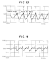
- Fig. 12 is a block diagram showing the general principle of feedback control. Assuming that the angular velocity command value applied to the motor is constant, the deviation between the encoder detection value ⁇ R and the command value ⁇ COMM is multiplied by an appropriate gain kp and the product is input to the motor as a velocity command value omega COMM, causing the motor to rotate by an amount omega R equal to omega COMM.
- Figs. 13 and 14 show data measured during actual use of this conventional control, Fig. 13 showing the relationship between the command values and the actual joint angles and Fig. 14 showing the corresponding lag. As can be seen from these figures, lag arises when the conventional control is employed.
- the earlier mentioned Japanese Laid-open Patent Publication No. 62-97006 discloses a control method with excellent possibility of enabling realization of a practicable robot.
- the joint angles are calculated offline as a time series in advance and the calculated data is output by an on-board computer during locomotion. Since according to this method data calculated by a computer independent of the robot is stored in the memory of the robot's on-board computer and used during locomotion to control the walking, the on-board computer can be a relatively low-performance machine.
- a system for controlling locomotion or a legged walking robot having a body link and a plurality of linkages each connected to the body link by a first drive joint and each including at least one second drive joint connecting an upper link and a lower link thereof, comprising: a servo motor for driving the joint; first means for outputting a command value of speed to drive the servo motor in response to a change rate of a target angle; and second means for calculating a deviation between the target angle and a real angle for carrying out feedback compensation of the command value in response to the deviation and a gain to be multiplied thereto.
- a system for controlling the locomot-on of a legged walking robot which is of simple configuration but is nevertheless able to prevent control deviation and ensure stable walking, and in which, in a control method using time series locomotion data calculated offline, is able to prevent control deviation and ensure stable walking in a simpler manner than has been possible heretofore.
- a biped walking robot as a specific embodiment of a legged walking robot.
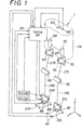
- An overall skeleton view of the biped walking robot is shown in Fig. 1.
- the robot designated by reference numeral 1
- the robot is provided with six joints (axes) on each of its right (R) and left (L) legs. From the top down, these joints (axes) are hip turning joints (axes) 10R, 10L, hip pitch direction joints (axes) 12R, 12L; hip roll direction joints (axes) 14R, 14L, knee pitch direction joints (axes) 16R, 16L, ankle pitch direction joints (axes) 18R, 18L, and ankle roll direction joints (axes) 20R, 20L.
- the pitch direction is the direction indicated by “x” and the roll direction is the direction indicated by “y” as shown in the right bottom of the figure.
- Feet 22R, 22L are attached below and a body (main unit) 24 is disposed at the uppermost position.
- the body 24 houses a control unit 26.
- joints (axes) 10R (L), 12R (L) and 14R (L) together constitute a right (left) hip joint.
- the three axes meet at a single point.
- the joints (axes) 18R (L) and 20R (L) together form a right (left) ankle, wherein these two axes also intersect perpendicularly.
- the three pitch direction joints (axes) 12R (L), 16R (L) and 18R (L) are mutually parallel and the positional relationship thereamong remains unchanged irrespective of the behavior of the other joints (axes).
- each leg has six degrees of freedom and each foot 22R (L) can be placed at the desired position in the desired direction irrespective of the fact that it is attached to the body 24.
- the legs as a whole can be moved as desired by appropriately driving the 12 (6 x 2) joints (axes) for varying their individual angles, thus enabling desired walking in three-dimensional space.
- the hip joints and the knee joints are connected by thigh linkages 27R, 27L and the knee joints and ankle joints are connected by crus linkages 28R, 28L.
- the joints are constituted mainly of motors and reduction gear mechanisms.
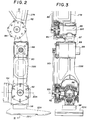
- the arrangement of the knee will now be explained in detail with reference to Figs. 2 and 3. Although a detailed description of the hip joints will not be given, it should be understood that they are of a similar structure to the knees. As the left and right legs are laterally symmetrical, only the right leg will be explained in the following.
- the output of a motor (not shown) mounted at an intermediate portion of the thigh linkage 27R is transmitted via a belt 82 to the input shaft of a harmonic reduction gear 84 installed at the knee joint (axis) 16R.
- the upper end of the crus linkage 28R is formed with a recess 87 which accommodates a motor 88, the output of which is input through a belt 90 to a harmonic reduction gear 92 provided at the ankle, whereby the right foot member 22R is driven in the pitch direction about the axis 18R.
- the foot 22R is further arranged to swing freely in the roll direction about the axis 20R perpendicularly intersecting the axis 18R.
- a harmonic reduction gear 94 for supplying power directly thereto.
- a motor 96 for supplying power directly thereto.
- Each of the motors is provided with a rotary encoder. (Only the rotary encoder 89 for the motor 88 is-shown in the drawings.)
- the ankle is further provided with a six-dimensional force and torque sensor 98 for measuring the x , y and z components transmitted to the robot through the foot and also separately measuring the three directional components of the moment, so as to detect whether or not the foot has landed and the force acting on the supporting leg.
- the bottom of the foot is approximately flat and is provided with elastic members 220 made of rubber or the like for absorbing the impact received at time the foot touches down.
- the four corners of the foot bottom are further provided with ground contact switches 99 (not shown in Figs. 2 and 3) of conventional design for detecting contact between the foot and ground. Further, as shown in Fig.
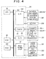
- a pair of inclination angle sensors 100, 102 are provided at an appropriate location on the body 24 for detecting (a) the amount of angle and angular velocity of the inclination relative to the z-axis in the x-z plane and (b) the amount of angle and angular velocity of the inclination relative to the z-axis in the y-z plane.
- the outputs of the inclination angle sensors 100, 102 are sent to the control unit 26 housed in the body 24.
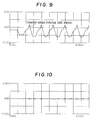
- the control unit 26 is constituted as a microcomputer.
- the outputs of the inclination angle sensors 100, 102 etc. are converted to digital values in an A/D converter 104, the output of which is forwarded to a RAM (random access memory) 108 via a bus 106.
- the outputs of the encoder 89 etc. are sent to the RAM 108 through a counter 110 and the outputs of the ground contact switches 99 etc. are passed through a wave forming circuit 112 and stored in the RAM 108.
- the control unit has a CPU (central processing unit) 114 which, in the manner to be explained later, reads in the stored locomotion data, calculates speed control commands on the basis of the deviation between the stored locomotion data and measured values received from the counter 110, and forwards the calculated speed control commands through a D/A converter 118 to a servo amplifier 120 for respective motor.
- the encoder output is further sent through an F/V converter 122 to,the servo amplifier 120, whereby a minor loop for speed feedback control is established in each motor.
- Reference numeral 128 designates a joy stick, 130 a zero reference switch for determining the origin (upright) posture, and 132 a limit switch for preventing overrun.
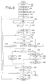
- step S10 the various sections of the system are initialized and then moves to step S12 where a locomotion pattern i ⁇ t is retrieved.
- This pattern indicates the joint angle target values for walking of the robot over an ideal flat surface of uniform hardness.
- the prefix "i” indicates the joint number and the suffix "t” indicates the joint angle at time "t”.
- step S14 the parameters kp, kv ... are read in. These are feedback gains which will be explained in detail later.
- step S16 the timer value t , the counter value COUNT and the joint number (counter) value i are reset to zero, whereafter walking is started in step S18 and the value of the counter for counting the joint numbers is set to 1 at step S20.
- the notation i ⁇ t+1 appearing in the flowchart indicates the target joint angle for the time t+1 following the current time t , namely for time at which the next program cycle begins.
- a value omega Dt indicates the target angular velocity (to be explained later).
- Ft(omega w) is a flag which indicates the two-leg support period
- Ft(omega s) a flag indicating the one-leg support period
- Ft(C) a flag indicating the impact absorption control period.
- the microcomputer determines when the procedure is in this period on the basis of the outputs from the respective six-dimensional force and torque sensor 98 and the like and sets the flag bit to 1 at this time.
- step S24 the outputs of the inclination sensors etc. are read in.
- a value i ⁇ R indicates the actual angle of the i-th joint
- omega R the actual inclination angular velocity
- M the actual moment acting on the foot.
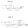
- a speed control value equal to the sum of a feedback value obtained by multiplying the deviation delta ⁇ between the joint angle command value i ⁇ t and the actual joint angle i ⁇ R by a proportional gain kp and a feedback value obtained by multiplying the deviation between the joint angle command value i ⁇ t at time t and the joint angle command value i ⁇ t+1 at time t+1 by a gain kv.
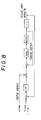
- the block diagram of Fig. 6 relates to the joints other than the ankle joints and that, as shown in the block diagram of Fig. 7, in the case of the ankle joints there are also fed back control values based on compliance control and the like. This will be explained in more detail later.
- step S30 discrimination is made as to whether or not the joint number has become 5 or greater, namely as to whether or not the control value of other than the ankle joints is in the process of being calculated, and since the result is of course negative, the procedure moves onto step S32 and the ensuing steps in which, first, inclination angular velocity feedback and the like are carried out.
- steps S32 to S34 it is discriminated whether the flag Ft(omega w) or flag Ft(omega s) is on (whether the robot is in a two-leg support state or a one-leg support state) and, based on the result of this discrimination, the procedure advances to step S36 or S38 in which a third speed feedback control value iV3 is calculated, as shown in Fig.7, by multiplying the deviation delta omega between the target inclination angular velocity omega Dt and the actual inclination angular velocity omega R by gain k omega.
- the control system implements stability control with respect to the ankle joints of the supporting leg for preventing the robot from toppling when it has been judged that the inclination angular velocity deviates from the target value or that an external moment is acting on the ankle joints.
- the control system drives the ankle joints of the supporting leg in accordance with the degree of deviation in order to produce a reactive force with respect to the ground and thus correct the robot's attitude as required to prevent the robot from falling over.
- the k omega is defined differently during the two-leg support period and during the one-leg support period.
- the control value in step S40 is zero.
- step S42 the virtual compliance control value is determined.
- a prescribed period TCOMP between footlift (the event of lifting a foot) and footfall of the robot's free leg is defined as the impact absorption control period Ft(C)
- step S42 the procedure goes to step S52 in which the control value iV4 is set to zero and then to step S54 in which the counter value is reset to zero.
- step S56 all of the calculated control values are added together to obtain a sum iVCOMM which is output to the servo amplifiers 120 for the motor concerned, whereafter the joint number counter is incremented in step S58, discrimination is conducted in step S60 as to whether this is the last joint and, if it is, the timer value t is incremented for retrieval of the next target joint angle in step S62 and, so long as it is not found,in step 64 that walking is to be discontinued, control values are continuously determined for the respective joints.
- the control is stabilized by reducing the load on the on-board computer through the provision of an analog circuit for velocity control, which has to be carried out in short control cycles, and a digital circuit for positional control, which can be carried out in relatively long control cycles.
- an analog circuit for velocity control which has to be carried out in short control cycles
- a digital circuit for positional control which can be carried out in relatively long control cycles.
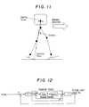
- open-loop control is adopted for the motor angular velocity so as to prevent delay from arising in the joint angle control and position feedback control is conducted only in cases where a deviation arises between the target joint angle and the actual joint angle owing to external disturbance or the like.
- Fig. 9 shows the relationship between the command values and the actual joint angles when the control system of the invention was used and Fig. 10 shows the corresponding lag.
- Figs. 13 and 14 shows that the control system of the invention substantially eliminates control deviation.
- the system according to the invention uses target joint angles calculated offline in advance, it greatly reduces the load on the on-board computer, while the fact that the difference between the current command value and the command value for the next cycle is used as the velocity command value, makes an even further simplification of the control system possible.
Landscapes
- Engineering & Computer Science (AREA)
- Chemical & Material Sciences (AREA)
- Combustion & Propulsion (AREA)
- Transportation (AREA)
- Mechanical Engineering (AREA)
- Manipulator (AREA)
- Control Of Position Or Direction (AREA)
Applications Claiming Priority (2)
| Application Number | Priority Date | Filing Date | Title |
|---|---|---|---|
| JP02336421A JP3078009B2 (ja) | 1990-11-30 | 1990-11-30 | 脚式移動ロボットの歩行制御装置 |
| JP336421/90 | 1990-11-30 |
Publications (3)
| Publication Number | Publication Date |
|---|---|
| EP0488692A2 true EP0488692A2 (de) | 1992-06-03 |
| EP0488692A3 EP0488692A3 (en) | 1993-02-24 |
| EP0488692B1 EP0488692B1 (de) | 1997-03-05 |
Family
ID=18298956
Family Applications (1)
| Application Number | Title | Priority Date | Filing Date |
|---|---|---|---|
| EP91310963A Expired - Lifetime EP0488692B1 (de) | 1990-11-30 | 1991-11-27 | System zur Steuerung der Fortbewegung eines Schreitroboters mit Beinen |
Country Status (4)
| Country | Link |
|---|---|
| US (1) | US5252901A (de) |
| EP (1) | EP0488692B1 (de) |
| JP (1) | JP3078009B2 (de) |
| DE (1) | DE69124942T2 (de) |
Cited By (3)
| Publication number | Priority date | Publication date | Assignee | Title |
|---|---|---|---|---|
| EP1110853A3 (de) * | 1999-12-24 | 2001-10-24 | Sony Corporation | Beweglicher Roboter mit Beinen und externes Modul für den Roboter |
| EP1844908A4 (de) * | 2004-12-14 | 2010-02-03 | Honda Motor Co Ltd | Mit beinen ausgestatteter mobiler roboter und steuerprogramm für den roboter |
| CN115157256A (zh) * | 2022-07-20 | 2022-10-11 | 燕山大学 | 可自动切换工作模式的遥操纵机器人系统控制方法 |
Families Citing this family (49)
| Publication number | Priority date | Publication date | Assignee | Title |
|---|---|---|---|---|
| JP3035051B2 (ja) * | 1991-12-20 | 2000-04-17 | 本田技研工業株式会社 | 脚式移動ロボットの歩行制御装置 |
| JP3167404B2 (ja) * | 1992-02-26 | 2001-05-21 | 本田技研工業株式会社 | ロボットの関節駆動制御装置 |
| US5337235A (en) * | 1992-03-12 | 1994-08-09 | Honda Giken Kogyo Kabushiki Kaisha | Locomotion control system for legged mobiled robot |
| US5455497A (en) * | 1992-04-20 | 1995-10-03 | Honda Giken Kogyo Kabushiki Kaisha | Legged mobile robot and a system for controlling the same |
| US5432417A (en) * | 1992-04-30 | 1995-07-11 | Honda Giken Kogyo Kabushiki Kaisha | Locomotion control system for legged mobile robot |
| US5416393A (en) * | 1992-05-20 | 1995-05-16 | Honda Giken Kogyo Kabushiki Kaisha | Legged mobile robot foot structure |
| JP3132156B2 (ja) * | 1992-05-22 | 2001-02-05 | 本田技研工業株式会社 | 脚式移動ロボットの歩容生成装置 |
| JP3269852B2 (ja) * | 1992-05-29 | 2002-04-02 | 本田技研工業株式会社 | 脚式移動ロボットの姿勢安定化制御装置 |
| US5404086A (en) * | 1992-07-20 | 1995-04-04 | Honda Giken Kogyo Kabushiki Kaisha | System for controlling locomotion of legged mobile robot and correcting inclinometer's output thereof |
| JP3278467B2 (ja) * | 1992-08-18 | 2002-04-30 | 本田技研工業株式会社 | 移動ロボットの制御装置 |
| US5459381A (en) * | 1992-10-28 | 1995-10-17 | Canon Kabushiki Kaisha | Composite system course control method and apparatus |
| US5631824A (en) * | 1994-05-26 | 1997-05-20 | Polytechnic University | Feedback control apparatus and method thereof for compensating for changes in structural frequencies |
| EP1118436B1 (de) * | 1999-04-05 | 2012-08-15 | Sony Corporation | Roboter, servoschaltkreis, aktuator, steuerungsverfahren für einen roboter und steuerungsverfahren für einen aktuator |
| US20010033145A1 (en) | 2000-02-14 | 2001-10-25 | Filo Andrew S. | Walking platforms with automatic self-stabilization |
| AU2001259610A1 (en) * | 2000-05-09 | 2001-11-20 | Hasbro, Inc. | Self-stabilizing walking apparatus that is capable of being reprogrammed or puppeteered |
| US6705917B2 (en) | 2000-12-15 | 2004-03-16 | Andrew S. Filo | Self-phase synchronized walking and turning quadruped apparatus |
| WO2003057423A1 (en) * | 2001-12-28 | 2003-07-17 | Honda Giken Kogyo Kabushiki Kaisha | Gait producing device for leg type movable robot |
| JP4808026B2 (ja) * | 2002-08-22 | 2011-11-02 | ヴィクソム ヒューマン バイオニクス インコーポレーテッド | 膝上部肢切断患者用の駆動源付き義足 |
| US7736394B2 (en) | 2002-08-22 | 2010-06-15 | Victhom Human Bionics Inc. | Actuated prosthesis for amputees |
| US7698020B2 (en) * | 2003-07-11 | 2010-04-13 | Honda Motor Co., Ltd. | Method of estimating joint moment of two-legged walking mobile body |
| CN1313251C (zh) * | 2003-08-21 | 2007-05-02 | 中国科学院合肥智能机械研究所 | 一种人形机器人脚及脚力信息检测方法 |
| US7815689B2 (en) * | 2003-11-18 | 2010-10-19 | Victhom Human Bionics Inc. | Instrumented prosthetic foot |
| US20050107889A1 (en) | 2003-11-18 | 2005-05-19 | Stephane Bedard | Instrumented prosthetic foot |
| US7637959B2 (en) | 2004-02-12 | 2009-12-29 | össur hf | Systems and methods for adjusting the angle of a prosthetic ankle based on a measured surface angle |
| CA2863933C (en) | 2004-12-22 | 2018-08-07 | Ossur Hf | Systems and methods for processing limb motion |
| US8801802B2 (en) | 2005-02-16 | 2014-08-12 | össur hf | System and method for data communication with a mechatronic device |
| US7339340B2 (en) * | 2005-03-23 | 2008-03-04 | Harris Corporation | Control system and related method for multi-limbed, multi-legged robot |
| SE528516C2 (sv) | 2005-04-19 | 2006-12-05 | Lisa Gramnaes | Kombinerat aktivt och passivt benprotessystem samt en metod för att utföra en rörelsecykel med ett sådant system |
| EP1942843B1 (de) | 2005-09-01 | 2017-03-01 | Össur hf | Vorrichtung und verfahren zur bestimmung der änderung des terrains |
| US7689320B2 (en) * | 2005-12-20 | 2010-03-30 | Intuitive Surgical Operations, Inc. | Robotic surgical system with joint motion controller adapted to reduce instrument tip vibrations |
| CA2673399C (en) | 2007-01-05 | 2017-08-29 | Victhom Human Bionics, Inc. | Joint actuation mechanism for a prosthetic and/or orthotic device having a compliant transmission |
| EP2120801B1 (de) | 2007-01-19 | 2018-04-11 | Victhom Laboratory Inc. | Reaktionsschicht-kontrollsystem für prothetische und orthotische vorrichtungen |
| EP2014425B1 (de) * | 2007-07-13 | 2013-02-20 | Honda Research Institute Europe GmbH | Verfahren und Vorrichtung zur Steuerung eines Roboters |
| CN102036626B (zh) | 2008-03-24 | 2014-07-02 | 奥瑟Hf公司 | 经股的假肢系统和用于操作该系统的方法 |
| US9060884B2 (en) | 2011-05-03 | 2015-06-23 | Victhom Human Bionics Inc. | Impedance simulating motion controller for orthotic and prosthetic applications |
| US9532877B2 (en) | 2011-11-11 | 2017-01-03 | Springactive, Inc. | Robotic device and method of using a parallel mechanism |
| US10543109B2 (en) | 2011-11-11 | 2020-01-28 | Össur Iceland Ehf | Prosthetic device and method with compliant linking member and actuating linking member |
| US9044346B2 (en) | 2012-03-29 | 2015-06-02 | össur hf | Powered prosthetic hip joint |
| EP3427702B1 (de) | 2013-02-26 | 2024-12-18 | Össur HF | Fussprothese mit verbesserter stabilität und elastischer energierückspeisung |
| WO2014159114A1 (en) | 2013-03-14 | 2014-10-02 | össur hf | Prosthetic ankle: a method of controlling based on adaptation to speed |
| WO2015157723A1 (en) | 2014-04-11 | 2015-10-15 | össur hf | Prosthetic foot with removable flexible members |
| CN105137972B (zh) * | 2015-08-14 | 2017-10-20 | 浙江大学 | 一种单关节助力外骨骼自适应鲁棒级联力控制的方法 |
| CN105965506A (zh) * | 2016-05-16 | 2016-09-28 | 北京格分维科技有限公司 | 一种基于遗传算法的人形双足机器人步行姿态控制方法 |
| CN106826759B (zh) * | 2016-12-29 | 2024-02-09 | 深圳市优必选科技有限公司 | 脚部结构及人形机器人 |
| CN109969284A (zh) * | 2017-12-28 | 2019-07-05 | 沈阳新松机器人自动化股份有限公司 | 混合式机械腿机构和双足机器人 |
| CN109774811A (zh) * | 2018-12-31 | 2019-05-21 | 南京工程学院 | 一种无刷直流电机驱动的小型双足机器人及其控制方法 |
| CN111113377B (zh) * | 2019-12-11 | 2023-03-14 | 桂林凯歌信息科技有限公司 | 具有姿态校准系统的人形机器人及其控制方法 |
| CN111232084B (zh) * | 2020-03-02 | 2021-08-31 | 广东博智林机器人有限公司 | 多足行走机器人 |
| CN111558941B (zh) * | 2020-07-14 | 2020-09-29 | 深圳市优必选科技股份有限公司 | 浮动基动力学前馈控制方法、装置和多足机器人 |
Family Cites Families (19)
| Publication number | Priority date | Publication date | Assignee | Title |
|---|---|---|---|---|
| US4202423A (en) * | 1978-04-20 | 1980-05-13 | Soto Jose M | Land vehicle with articulated legs |
| JPS5685106A (en) * | 1979-12-14 | 1981-07-11 | Hitachi Ltd | Robot teaching method |
| US4641251A (en) * | 1982-02-16 | 1987-02-03 | Inoue-Japax Research Incorporated | Robot |
| JPS59231607A (ja) * | 1983-06-14 | 1984-12-26 | Mitsubishi Electric Corp | ロボツトの制御装置 |
| US4621332A (en) * | 1983-06-20 | 1986-11-04 | Hitachi, Ltd. | Method and apparatus for controlling a robot utilizing force, position, velocity, spring constant, mass coefficient, and viscosity coefficient |
| JPH063994B2 (ja) * | 1984-10-05 | 1994-01-12 | 株式会社日立製作所 | 複数台デイジタルサーボの制御方法 |
| JPS61146482A (ja) * | 1984-12-20 | 1986-07-04 | 工業技術院長 | 異構造異自由度バイラテラル・マスタスレイブ・マニピユレ−タの制御装置 |
| JPS6297006A (ja) * | 1985-10-23 | 1987-05-06 | Hitachi Ltd | 多関節歩行ロボツト制御装置 |
| US5040626A (en) * | 1986-02-12 | 1991-08-20 | Nathaniel A. Hardin | Walking robots having double acting fluid driven twistor pairs as combined joints and motors and method of locomotion |
| US4826392A (en) * | 1986-03-31 | 1989-05-02 | California Institute Of Technology | Method and apparatus for hybrid position/force control of multi-arm cooperating robots |
| JPS63150176A (ja) * | 1986-12-15 | 1988-06-22 | 工業技術院長 | 動的歩行ロボツトの歩行制御方法 |
| JP2645004B2 (ja) * | 1987-02-27 | 1997-08-25 | 株式会社東芝 | 多自由度マニピユレータの制御装置 |
| JP2713899B2 (ja) * | 1987-03-30 | 1998-02-16 | 株式会社日立製作所 | ロボツト装置 |
| JPH01304511A (ja) * | 1988-06-02 | 1989-12-08 | Seiko Instr Inc | サーボ制御装置 |
| JPH0688218B2 (ja) * | 1988-06-13 | 1994-11-09 | 工業技術院長 | 歩行脚制御装置 |
| JPH0822514B2 (ja) * | 1988-08-09 | 1996-03-06 | 工業技術院長 | 歩行制御装置 |
| US5005658A (en) * | 1988-12-22 | 1991-04-09 | Carnegie-Mellon University | Orthogonal legged walking robot |
| JP2520019B2 (ja) * | 1989-06-29 | 1996-07-31 | 本田技研工業株式会社 | 脚式移動ロボットの駆動制御装置 |
| US5021878A (en) * | 1989-09-20 | 1991-06-04 | Semborg-Recrob, Corp. | Animated character system with real-time control |
-
1990
- 1990-11-30 JP JP02336421A patent/JP3078009B2/ja not_active Expired - Lifetime
-
1991
- 1991-11-27 US US07/800,646 patent/US5252901A/en not_active Expired - Lifetime
- 1991-11-27 EP EP91310963A patent/EP0488692B1/de not_active Expired - Lifetime
- 1991-11-27 DE DE69124942T patent/DE69124942T2/de not_active Expired - Lifetime
Cited By (5)
| Publication number | Priority date | Publication date | Assignee | Title |
|---|---|---|---|---|
| EP1110853A3 (de) * | 1999-12-24 | 2001-10-24 | Sony Corporation | Beweglicher Roboter mit Beinen und externes Modul für den Roboter |
| US6538410B2 (en) | 1999-12-24 | 2003-03-25 | Sony Corporation | Legged mobile robot and external module for the robot |
| EP1844908A4 (de) * | 2004-12-14 | 2010-02-03 | Honda Motor Co Ltd | Mit beinen ausgestatteter mobiler roboter und steuerprogramm für den roboter |
| US7860613B2 (en) | 2004-12-14 | 2010-12-28 | Honda Motor Co., Ltd. | Legged mobile robot and control program for the robot |
| CN115157256A (zh) * | 2022-07-20 | 2022-10-11 | 燕山大学 | 可自动切换工作模式的遥操纵机器人系统控制方法 |
Also Published As
| Publication number | Publication date |
|---|---|
| DE69124942D1 (de) | 1997-04-10 |
| EP0488692A3 (en) | 1993-02-24 |
| EP0488692B1 (de) | 1997-03-05 |
| JPH04201190A (ja) | 1992-07-22 |
| JP3078009B2 (ja) | 2000-08-21 |
| DE69124942T2 (de) | 1997-06-19 |
| US5252901A (en) | 1993-10-12 |
Similar Documents
| Publication | Publication Date | Title |
|---|---|---|
| EP0488692B1 (de) | System zur Steuerung der Fortbewegung eines Schreitroboters mit Beinen | |
| EP0488691B1 (de) | System zur Steuerung der Fortbewegung eines Schreitroboters mit Beinen | |
| US5355064A (en) | Control system for legged mobile robot | |
| EP0488693B1 (de) | System zur Steuerung der Fortbewegung eines Schreitroboters mit Beinen | |
| US5426586A (en) | Robot drive joint control system | |
| US5311109A (en) | Locomotion control system for legged mobile robot | |
| EP0587327B1 (de) | Steuerungssystem für die Fortbewegung eines mobilen Roboters | |
| US5838130A (en) | Locomotion control system of legged mobile robot | |
| EP0478393B1 (de) | Steuerungssystem für die Fortbewegung eines Schreit-Roboters | |
| US5349277A (en) | Control system for legged mobile robot | |
| US5513106A (en) | System for controlling locomotion of a walking robot having a sensor for detecting externally exerted forces | |
| US5594644A (en) | Method and system for generating trajectory of robot and the like | |
| JP2004223712A (ja) | 歩行式ロボット及びその位置移動方法 | |
| JP3167420B2 (ja) | 脚式移動ロボットの歩行制御装置 | |
| JP3270766B2 (ja) | 脚式移動ロボットの制御装置 | |
| CN100588509C (zh) | 步行式机器人及步行式双腿机器人 | |
| JP3167406B2 (ja) | 脚式移動ロボットの歩行制御装置 | |
| JP3024023B2 (ja) | 脚式移動ロボットの歩行制御装置 | |
| JP2911984B2 (ja) | 脚式移動ロボットの歩行制御装置 | |
| JP3071028B2 (ja) | 脚式移動ロボットの歩行制御装置 | |
| JP3167407B2 (ja) | 脚式移動ロボットの歩行制御装置 | |
| JP2997038B2 (ja) | 脚式移動ロボットの歩行御制装置 | |
| JP2997037B2 (ja) | 脚式移動ロボットの歩行制御装置 | |
| JPH06182679A (ja) | リンク式ロボットの制御装置 | |
| JP3073306B2 (ja) | 脚式移動ロボットの歩行制御装置 |
Legal Events
| Date | Code | Title | Description |
|---|---|---|---|
| PUAI | Public reference made under article 153(3) epc to a published international application that has entered the european phase |
Free format text: ORIGINAL CODE: 0009012 |
|
| AK | Designated contracting states |
Kind code of ref document: A2 Designated state(s): DE FR GB |
|
| PUAL | Search report despatched |
Free format text: ORIGINAL CODE: 0009013 |
|
| AK | Designated contracting states |
Kind code of ref document: A3 Designated state(s): DE FR GB |
|
| 17P | Request for examination filed |
Effective date: 19930406 |
|
| 17Q | First examination report despatched |
Effective date: 19940811 |
|
| GRAG | Despatch of communication of intention to grant |
Free format text: ORIGINAL CODE: EPIDOS AGRA |
|
| GRAH | Despatch of communication of intention to grant a patent |
Free format text: ORIGINAL CODE: EPIDOS IGRA |
|
| GRAH | Despatch of communication of intention to grant a patent |
Free format text: ORIGINAL CODE: EPIDOS IGRA |
|
| GRAA | (expected) grant |
Free format text: ORIGINAL CODE: 0009210 |
|
| AK | Designated contracting states |
Kind code of ref document: B1 Designated state(s): DE FR GB |
|
| REF | Corresponds to: |
Ref document number: 69124942 Country of ref document: DE Date of ref document: 19970410 |
|
| ET | Fr: translation filed | ||
| PLBE | No opposition filed within time limit |
Free format text: ORIGINAL CODE: 0009261 |
|
| STAA | Information on the status of an ep patent application or granted ep patent |
Free format text: STATUS: NO OPPOSITION FILED WITHIN TIME LIMIT |
|
| 26N | No opposition filed | ||
| REG | Reference to a national code |
Ref country code: GB Ref legal event code: IF02 |
|
| PGFP | Annual fee paid to national office [announced via postgrant information from national office to epo] |
Ref country code: FR Payment date: 20101123 Year of fee payment: 20 |
|
| PGFP | Annual fee paid to national office [announced via postgrant information from national office to epo] |
Ref country code: DE Payment date: 20101124 Year of fee payment: 20 |
|
| PGFP | Annual fee paid to national office [announced via postgrant information from national office to epo] |
Ref country code: GB Payment date: 20101124 Year of fee payment: 20 |
|
| REG | Reference to a national code |
Ref country code: DE Ref legal event code: R071 Ref document number: 69124942 Country of ref document: DE |
|
| REG | Reference to a national code |
Ref country code: DE Ref legal event code: R071 Ref document number: 69124942 Country of ref document: DE |
|
| REG | Reference to a national code |
Ref country code: GB Ref legal event code: PE20 Expiry date: 20111126 |
|
| PG25 | Lapsed in a contracting state [announced via postgrant information from national office to epo] |
Ref country code: GB Free format text: LAPSE BECAUSE OF EXPIRATION OF PROTECTION Effective date: 20111126 |
|
| PG25 | Lapsed in a contracting state [announced via postgrant information from national office to epo] |
Ref country code: DE Free format text: LAPSE BECAUSE OF EXPIRATION OF PROTECTION Effective date: 20111128 |