EP0488312B1 - Verfahren zum Herstellen eines Systemfussbodens und Bodenstützfläche für Systemfussboden - Google Patents
Verfahren zum Herstellen eines Systemfussbodens und Bodenstützfläche für Systemfussboden Download PDFInfo
- Publication number
- EP0488312B1 EP0488312B1 EP91120431A EP91120431A EP0488312B1 EP 0488312 B1 EP0488312 B1 EP 0488312B1 EP 91120431 A EP91120431 A EP 91120431A EP 91120431 A EP91120431 A EP 91120431A EP 0488312 B1 EP0488312 B1 EP 0488312B1
- Authority
- EP
- European Patent Office
- Prior art keywords
- floor
- props
- prop
- base
- floor base
- Prior art date
- Legal status (The legal status is an assumption and is not a legal conclusion. Google has not performed a legal analysis and makes no representation as to the accuracy of the status listed.)
- Expired - Lifetime
Links
Images


Classifications
-
- H—ELECTRICITY
- H02—GENERATION; CONVERSION OR DISTRIBUTION OF ELECTRIC POWER
- H02G—INSTALLATION OF ELECTRIC CABLES OR LINES, OR OF COMBINED OPTICAL AND ELECTRIC CABLES OR LINES
- H02G3/00—Installations of electric cables or lines or protective tubing therefor in or on buildings, equivalent structures or vehicles
- H02G3/28—Installations of cables, lines, or separate protective tubing therefor in conduits or ducts pre-established in walls, ceilings or floors
- H02G3/283—Installations of cables, lines, or separate protective tubing therefor in conduits or ducts pre-established in walls, ceilings or floors in floors
- H02G3/285—Installations of cables, lines, or separate protective tubing therefor in conduits or ducts pre-established in walls, ceilings or floors in floors in modular floors, e.g. access floors
-
- E—FIXED CONSTRUCTIONS
- E04—BUILDING
- E04F—FINISHING WORK ON BUILDINGS, e.g. STAIRS, FLOORS
- E04F15/00—Flooring
- E04F15/02—Flooring or floor layers composed of a number of similar elements
- E04F15/024—Sectional false floors, e.g. computer floors
- E04F15/02405—Floor panels
- E04F15/02411—Floor panels with integrated feet
-
- E—FIXED CONSTRUCTIONS
- E04—BUILDING
- E04F—FINISHING WORK ON BUILDINGS, e.g. STAIRS, FLOORS
- E04F15/00—Flooring
- E04F15/02—Flooring or floor layers composed of a number of similar elements
- E04F15/024—Sectional false floors, e.g. computer floors
- E04F15/02447—Supporting structures
-
- E—FIXED CONSTRUCTIONS
- E04—BUILDING
- E04F—FINISHING WORK ON BUILDINGS, e.g. STAIRS, FLOORS
- E04F15/00—Flooring
- E04F15/02—Flooring or floor layers composed of a number of similar elements
- E04F15/024—Sectional false floors, e.g. computer floors
- E04F15/02447—Supporting structures
- E04F15/02464—Height adjustable elements for supporting the panels or a panel-supporting framework
- E04F15/0247—Screw jacks
- E04F15/02476—Screw jacks height-adjustable from the upper side of the floor
-
- E—FIXED CONSTRUCTIONS
- E04—BUILDING
- E04F—FINISHING WORK ON BUILDINGS, e.g. STAIRS, FLOORS
- E04F15/00—Flooring
- E04F15/02—Flooring or floor layers composed of a number of similar elements
- E04F15/024—Sectional false floors, e.g. computer floors
- E04F15/02447—Supporting structures
- E04F15/02494—Supporting structures with a plurality of base plates or like, each base plate having a plurality of pedestals upstanding therefrom to receive the floor panels
Definitions
- the present invention relates to a system floor comprising a rectangular floor base member with protruding props and a floor panel supported by said props, and to a method for manufacturing a floor base for the system floor which are used to provide an underfloor shielding wire such as a power cable and a signal cable for various types of equipments realizing an office automation.
- Insertion blocks having specific forms to be engaged with each are integrally formed on a peripheral portion of a rectangular floor base to be formed on a base floor. Then, the rectangular floor base is formed on the surface of the base floor as the insertion blocks are coupled to each other.
- Japanese Patent Application No. 60-40472 discloses the following structure: A plurality of props is formed on a lower unit, and an upper unit is mounted to be fixed to the lower unit by these props, thereby the upper unit is formed on the surface of the basic floor.
- a bottom plate or a bottom portion of a base member which is called a base plate
- a base plate are shaped flat. Due to this, a rickety state is generated if the base member is not formed to be flush with the surface of the base floor, so that conformability to the surface of the base floor is lost.
- a high flat accuracy is required in finishing the surface of the base floor. Therefore, there are problems in the various points such as a construction cost, a construction period of time, and workability.
- the upper unit is mounted to be fixed to the lower unit by the plurality of props
- the lower units are arranged on the surface of the base floor and the upper units are mounted to be fixed thereto, the construction work is relatively easily carried out.
- the lower units are integrally coupled to each other, the stability of the upper floor surface and flatness are lost.
- Japanese Patent Application No. 1-242835 discloses a floor base having the structure in which the props having the same height are formed on each latticed frame cross section, and support a floor panel at many points, and conformability to the surface of the base floor is good and construction work can be easily carried out.
- Another floor system described in EP-A-0 385 876 A1 essentially is only formed by floor panels having their support members formed on the lower side thereof. Height adjusting means are arranged in a space in the corner of four adjacing floor panels and supported directly on the floor. With this prior art floor system only the four adjacing floor panels can be adjusted altogether with respect to their height positions and a comparatively large opening is required in the corner portions of the floor members. Further, with this known height adjusting structure either a range of height adjustment is small or an adjustment screw member is likely to project beyond the top surface of the floor panels.
- An object of the invention is to provide a floor system in which the number of parts is reduced and a flat adjustment is simply and quickly carried out while durability and conformability are improved.
- Another object of the present invention is to provide a method for manufacturing a floor base in which the number of structural parts can be minimized and the floor base can be easily manufactured with reasonable cost.
- the system floor of the present invention comprises the features recited in claim 1 and the method for manufacturing a floor base according to the invention comprises the steps defined in claim 7.
- a floor structure in which the number of the parts can be reduced, the structure is simplified, the construction work can be easily and quickly carried out, the manufacturing cost can be reduced, and durability and conformability are improved.
- the number of the structural parts is minimized, the floor can be easily manufactured with the simple structure and reasonable cost.
- Figs. 1 through 6 show one embodiment of the present invention.
- Fig. 1 is an exploded perspective view showing the entire structure of a floor panel.
- Fig. 2 is a plane view showing the floor base.
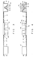
- Fig. 3 is a cross sectional view taken along the line A - A of Fig. 2.
- Fig. 4 is a cross sectional view showing the enlarged structure of a prop portion of the corner shown in Figs. 1 and 2.
- Fig. 5 is a cross sectional view showing a state that an electrical part is attached to a central prop (auxiliary prop) shown in Figs. 1 to 2.
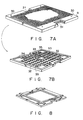
- Fig. 6 is a perspective view showing the structure of the floor panel shown in Fig. 1.
- reference numeral 1 is a floor base formed on a surface B of a base floor.
- Reference numeral 11 is a skin, which is a structural element of the floor base 1 and formed of rectangular synthetic resin to which a press molding process is added.
- the skin 11 there are formed convex portions 11a, 11a, ... integrally projecting to the upper surface side in the four corners and the central portion and concave portions 11b, 11b, ... on the lower surface side by the press molding process.
- an adjusting screw 2 with a plate for adjusting the height is embedded in the upper surface of each of props 13, 13, ... of the four corners. More specifically, on the upper surface portion of the convex portion of 11a, 11a, ..., constituting the props 13, 13, ... there is formed a storing space 11c comprising a storing hole 131 for a base seat portion 21 of the adjusting screw 2 with plate, a storing and holding hole 132 for a nut 23 screwed to a bolt 22 (see Fig.
- the adjusting screw 2 with plate which comprises the base seat portion 21, the bolt 22, and the nut screwed to the bolt 22, is stored in the concave space portion 11c having these holes 131, 132, and 133.
- An angular hole 21a engaging with a hexagonal wrench is formed in the central portion of the upper portion of the base seat portion 21 of the adjusting screw 2 with plate. The hexagonal wrench is inserted into the angular hole 21a through a wrench through hole 30 formed on the four corners of the floor panel 3, thereby making it possible to easily adjust the height of each of the props 13, 13, ...
- a storing space 11d is formed on an upper side and a U-shape groove 14a (see Fig. 6) is formed in each side of the auxiliary prop 14. Then, as shown in Fig. 6, if an electrical part 51 such as a power plug socket, a distributor, a connector, a receiver, a transmitter, and the like is embedded in the storing space 11d in the auxiliary prop 14, the groove 14a is used as an outlet for a cable 52 or an inlet.
- a floor panel 3, is supported at a constant position on the floor base 1 through props 13, 13, ....
- rectangular opening portions 31, 31 are respectively formed in the opposing two sides.
- a main rib 32 having a constant width is formed in the peripheral portion of the lower surface, and an auxiliary rib 33 is formed in a face portion other than the main rib 32.
- the prop connecting portions 34 and 35 or the thickness of the shock absorbing member are adjusted such that in case a large load is applied to the base panel 3 the auxiliary prop 14 of the central portion receives a part of the load.
- the electrical part 51 such as the power plug socket, the distributor, the connector, the receiver, the transmitter, and the like is embedded in the auxiliary prop 14, there is used a floor panel 3s in which a hole is formed, in advance, in the prop connecting portion 35 formed to correspond to the auxiliary prop 14 of the back surface of the panel shown in Fig. 7B.
- connection piece 4 has insertion holes into which the props 13 of the corner portions are inserted.
- the connection piece is placed over the props 13, 13, ... of the corners when the adjacent floor bases 1, 1, ... are mutually connected.
- a horizontal separator 5 forms a wiring layer.
- the separator 5 is hooked on two hook projection portions 15 and 15 formed on each side to be spaced from the outer wall surface of the auxiliary prop 14 on the floor base 1 and which is guided to an arbitrary space on the floor base 1 to be divided in the upper and lower directions.
- a hinge portion is formed on the upper side of the hook portion to be opened upward.
- the horizontal separator 5 is secured to a fixed position where the space between the floor base 1 and the floor panel 3 is divided into two by a leg portion formed on both sides of the hook portions.
- the floor base 1 integrally having strong props 13, 13, ..., 14.
- the skin 11 formed of the rectangular synthetic resin sheet constitutes the main body (base) and strong props 13, 13, ..., 14 can be integrally formed, the floor base can be manufactured with low cost by the simple manufacturing method and the structure comprises only a small number of parts.
- the construction work of the above-structured system floor will be carried out as follows: First, the floor bases 1, 1, ... are sequentially juxtaposed on a basic floor surface B such that their ends are arranged in order. Then, the connection pieces 4 are inserted onto the props 13, 13, ... of the corners, thereby the juxtaposed floor bases 1, 1, ... are coupled to each other.
- the floor bases 1, 1, ... can be formed on the base floor surfaces B by this simple manner.
- the horizontal separator 5 is fixed to be hooked to the arbitrary hook projection portions 15, 15 on the floor base 1, and a predetermined wiring passage, a duct and the like are formed, and a predetermined wiring process is carried out. Thereafter, the floor panels 3, 3, ... are mounted on the floor bases 1, 1, ....
- the floor panels 3 are supported on the props 13 of four corners, which are formed on the floor bases 1, and the central auxiliary prop 14 through the shock absorbing material. Moreover, the props 13 of four corners are engaged with the main rib 32 of the floor panel 3 and the central auxiliary prop 14 is engaged with the auxiliary rib 33, thereby the floor panel 3 is secured to the fixed position on the floor base 1. In this case, a load to be applied to the floor panel 3 is dispersed and the dispersed load is applied to the props 13 serving as a main prop, and the prop 14 serves as an auxiliary prop.
- a load which is applied to the shock absorbing member between the auxiliary prop 14 formed in the central portion on the floor base 1 and the prop connecting portion 35 formed in the central portion of the lower surface of the floor base 3, is considerably small.
- the auxiliary prop 14 of the central portion functions upon receipt of a part of the load.
- the hexagonal wrench is inserted into one of wrench-through holes 30 formed in the four corners of the floor panel 3.
- the top end of the wrench is engaged with the angular hole 21a, which is formed in the central portion of the upper portion of the base seat portion 21 of the adjusting screw 2 with plate. Then, the adjusting screw is rotated, thereby the adjustment of height can be performed in a state the floor panel 3 is constructed.
- system floor multifunctional system floor
- the skin 11 formed of the rectangular synthetic resin sheet is formed in the main body (base) and strong props 13, 13, ..., 14 can be integrally formed.
- the floor base 1 can be manufactured by the simple manufacturing processes and the floor base 1 can be easily manufactured by the small number of parts. Thereby, the system floor having high reliability can be provided with low cost.
- the main rib 32 and the auxiliary rib 33 which are formed in the lower portion of the floor panel 3, are respectively engaged with the props 13 and 14 of the corner portions and the central portion, which are formed on the floor base 1. Then, the floor panel 3 is supported at the constant position on the floor base 1.
- the floor panel 3 can be secured to the fixed position on the floor base and supported. Also, the weight of the floor panel can be lightened and the cost thereof can be reduced. Moreover, the floor structure can be simplified and easily and quickly constructed. Furthermore, the floor structure has high durability to fully withstand the large load.
- the floor panel 3 is supported at the fixed position on the floor base 1 by the props 13 of the corners and the auxiliary prop 14 of the central portion, which are formed on the floor base 1. Moreover, the auxiliary prop 14 of the central portion functions when the large load is applied to the floor panel 3. Due to this, by use of the structure having the minimum number of props, there can be realized the system floor having high durability to fully withstand the large load, and excellent conformability.
- Fig. 8 shows the rib structure of the floor panel according to the other embodiment.
- This embodiment shows the floor panel structure having a rib, which are shaped in parallel crosses, and which is parallel with each side. The props 13 of the corners are engaged with two sides of the rib, and the floor panel is supported at the fixed position on the floor base 1.
- the floor panel 3 is supported by five props 13 and 14 formed on the floor base 1.
- the respective convex portions 11a and 11c which are integrally project to the upper surface side, are formed in the four corners of the skin 11 and the central portion.
- the concave portions 11b are formed in the lower surface side, and ultra-high-strength special light-weight concrete 12 is packed therein, thereby there is formed the central auxiliary prop 14, which is slightly lower than the props 13 of the four corners, integrated in the skin 11.
- the structure of the floor base and that of the floor panel are not limited to the above-mentioned structure, and the other sheet-like material may be used.
Claims (8)
- Systemfußboden, umfassend ein rechteckiges Fußbodenbasiselement (1) mit hochragenden Stützen (13, 14) und einem von den Stützen (13, 14) getragenen oder abgestützten Fußbodenpaneel (3), wobei an der Oberseite einer jeden Stütze (13) ein erster Aufnahmeraum (11c) geformt ist,
dadurch gekennzeichnet, daß
das Fußbodenbasiselement (1) die hochragenden Stützen (13) zumindest an jeder Ecke desselben materialeinheitlich angeformt aufweist,
in den ersten Aufnahmeraum (11c) jeder Stütze (13) Höheneinstellelemente (2) eingelassen sind, die mit Mitteln zum variablen Einstellen der Höhe einer Stützposition in einem vorbestimmten Bereich zwischen einer im wesentlichen einer Oberseite der Stütze (13) entsprechenden unteren Position und einer höheren, über der Oberseite der Stütze (13) gelegenen Position versehen sind, und
das Fußbodenpaneel (3) Durchgangs-Öffnungen oder -Bohrungen (30) aufweist, die entsprechend den Positionen der Höheneinstellelemente angeordnet sind und das Einführen eines Werkzeugs zum Einstellen der Stützposition des betreffenden Höheneinstellelements (2) erlauben. - System(fußboden) nach Anspruch 1, dadurch gekennzeichnet, daß eine weitere hochragende Stütze (14) in einem Mittelbereich des Fußbodenbasiselements (1) vorgesehen ist und ein zweiter Aufnahmeraum (11d) an einer Oberseite der Stütze (14) im Mittelbereich geformt ist,
der zweite Aufnahmeraum (11d) so geformt ist, daß er ein in ihn eingelassenes elektrisches Bauelement (51) aufnimmt, und
im Mittelbereich des Fußbodenpaneels (3) ein Öffnungsabschnitt (35) geformt ist, durch den hindurch eine Oberseite des elektrischen Bauelements (51) nach außen hin freiliegt. - Systemfußboden nach Anspruch 1 oder 2, dadurch gekennzeichnet, daß das Höheneinstellelement (2) eine in den ersten Aufnahmeraum (11c) eingelassene (Schrauben-)Mutter (23) und einen in die Mutter (23) eingeschraubten Schraubbolzen (22) mit einem Sitz (21) aufweist.
- Systemfußboden nach Anspruch 1, 2 oder 3, dadurch gekennzeichnet, daß das Fußbodenbasiselement (1) mit einer als eine (Außen-)Haut dienenden rechteckigen Kunstharzlage versehen ist,
die materialeinheitlich angeformten, hochragenden Stützen (13) durch Konvexabschnitte (11a) gebildet sind, die mit der Lage materialeinheitlich ausgebildet sind und an mindestens vier Ecken der Lage zur Oberflächenseite hochstehen,
in einer Innenfläche jedes Konvexabschnitts (11a) Konkavabschnitte (11b) geformt sind und
in die Konkavabschnitte (11b) Beton eingefüllt ist. - Systemfußboden nach Anspruch 4, dadurch gekennzeichnet, daß im Konvexabschnitt (11a) ein in den ersten Aufnahmeraum (11c) hineinreichender Mutterfassungsabschnitt (132) geformt ist und die Mutter (23) in den Mutterfassungsabschnitt (132) eingelassen ist.
- Systemfußboden nach einem der Ansprüche 1 bis 5, dadurch gekennzeichnet, daß in einem Randabschnitt oder einem Teil des Randabschnitts des Fußbodenbasiselements (1) ein Anstoßvorsprung (16) zur Verhinderung der Überlappung benachbarter Fußbodenbasiselemente (1) geformt ist.
- Verfahren zur Herstellung einer Fußbodenbasis (1), umfassend die folgenden Schritte:
Formen von materialeinheitlich zur Oberflächenseite hochstehenden Konvexabschnitten (11a) an mindestens vier Ecken einer aus einer rechteckigen Kunstharzlage geformten (Außen-) Haut (11),
Formen von Konkavabschnitten (11b) in der Innenfläche der Konvexabschnitte (11a),
Einfüllen von Beton (12) in die Konkavabschnitte (11b) und
Aushärten- oder Abbindenlassen des Betons (12) zwecks Ausbildung von mit der Fußbodenbasis materialeinheitlichen hochragenden Stützen (13). - Verfahren nach Anspruch 7, dadurch gekennzeichnet, daß in die Konkavabschnitte (11b) ein Spezial-Leichtbeton (12) ultrahoher Festigkeit aus einem hochfesten, anorganischen Material eingefüllt und der Beton in den Konkavabschnitten (11b) durch Schwingungseinwirkung auf die Haut (11) ausgehärtet bzw. abbinden gelassen wird.
Applications Claiming Priority (4)
| Application Number | Priority Date | Filing Date | Title |
|---|---|---|---|
| JP333076/90 | 1990-11-29 | ||
| JP333075/90 | 1990-11-29 | ||
| JP02333075A JP3095409B2 (ja) | 1990-11-29 | 1990-11-29 | システムフロア |
| JP02333076A JP3095410B2 (ja) | 1990-11-29 | 1990-11-29 | フロアベースの製造方法 |
Publications (2)
| Publication Number | Publication Date |
|---|---|
| EP0488312A1 EP0488312A1 (de) | 1992-06-03 |
| EP0488312B1 true EP0488312B1 (de) | 1995-01-18 |
Family
ID=26574386
Family Applications (1)
| Application Number | Title | Priority Date | Filing Date |
|---|---|---|---|
| EP91120431A Expired - Lifetime EP0488312B1 (de) | 1990-11-29 | 1991-11-28 | Verfahren zum Herstellen eines Systemfussbodens und Bodenstützfläche für Systemfussboden |
Country Status (3)
| Country | Link |
|---|---|
| US (1) | US5386670A (de) |
| EP (1) | EP0488312B1 (de) |
| DE (1) | DE69106852T2 (de) |
Families Citing this family (57)
| Publication number | Priority date | Publication date | Assignee | Title |
|---|---|---|---|---|
| JP3638679B2 (ja) * | 1995-03-06 | 2005-04-13 | オーエム機器株式会社 | フリーアクセスフロア |
| US6101768A (en) * | 1995-09-11 | 2000-08-15 | Springstead; Gary | Center supported ventilated raised floor with grated core |
| US6460303B1 (en) | 1996-07-19 | 2002-10-08 | Tac-Fast Georgia L.L.C. | Hook and loop anchor sheet module with overlapped edges and sufficient mass to resist buckling |
| US6395362B1 (en) | 1996-07-19 | 2002-05-28 | Tac-Fast Georgia, L.L.C. | Anchor sheet framework and subflooring |
| US6306477B1 (en) | 1996-07-19 | 2001-10-23 | Tac-Fast Georgia, L.L.C. | Covering module and anchor sheet |
| US7185473B2 (en) | 1996-07-19 | 2007-03-06 | Tac-Fast Georgia, L.L.C. | Anchor sheet and anchor sheet module |
| US6298624B1 (en) * | 1996-07-19 | 2001-10-09 | Tac-Fast Georgia, L.L.C. | Anchor sheet and anchor sheet module |
| US20070204556A1 (en) * | 1996-07-19 | 2007-09-06 | Tac-Fast Georgia L.L.C. | Covering module and anchor sheet |
| GB2330595B (en) * | 1996-07-31 | 2001-03-14 | Kyodo Ky Tec Corp | Floor panel including support portions and method of laying the same |
| ITMI962315A1 (it) * | 1996-11-07 | 1998-05-07 | Pmf Lavorazioni Metalliche S R | Pavimento a piastrelle |
| BR9714373A (pt) * | 1996-12-04 | 2000-07-11 | Miller Herman Inc | Ladrilho para soalhos modulares e sistema de soalhos |
| DE19861051C2 (de) * | 1998-03-10 | 2002-05-02 | Deutsche Telekom Ag | Deckensystem |
| AUPP392898A0 (en) * | 1998-06-05 | 1998-07-02 | Ribaric, Anthony | Multi-web construction |
| WO2000074544A1 (en) * | 1999-06-07 | 2000-12-14 | Tac-Fast Systems S.A. | Anchor sheet attachment devices |
| US6637161B1 (en) | 2000-11-28 | 2003-10-28 | Steelcase Development Corporation | Floor system |
| FR2821916B1 (fr) | 2001-03-09 | 2003-05-16 | Vallourec Mannesmann Oil & Gas | Element filete pour joint filete tubulaire resistant a la fatigue |
| US6748707B1 (en) | 2001-07-24 | 2004-06-15 | Steelcase Development Corporation | Utility interface system |
| US7412806B2 (en) * | 2001-12-13 | 2008-08-19 | Tac-Fast Georgia Llc | Structures for creating spaces while installing anchor sheet and attachment piece subfloors |
| US7024261B1 (en) | 2001-12-17 | 2006-04-04 | Tanton Chris D | Modular automation apparatus |
| ATE394050T1 (de) * | 2003-01-30 | 2008-05-15 | Joseph Rocco Pacione | Positionier- und verbindungssystem für haftunterlage |
| US20060162269A1 (en) * | 2003-01-30 | 2006-07-27 | Pacione Joseph R | Anchor sheet |
| ATE339138T1 (de) * | 2003-01-30 | 2006-10-15 | Joseph Rocco Pacione | Fussbodenbelag mit einer entfernbaren ziereinlage |
| CA2514015A1 (en) * | 2003-01-30 | 2004-08-12 | Joseph Rocco Pacione | Carpet tile, installation, and methods of manufacture and installation thereof |
| US20060003141A1 (en) * | 2004-06-30 | 2006-01-05 | Pacione Joseph R | Floor covering having a removable decorative inlay |
| US7610731B1 (en) * | 2005-01-10 | 2009-11-03 | Comc, Llc | Snap together floor structure |
| TWM281040U (en) * | 2005-07-07 | 2005-11-21 | Shao-Jay Din | The structure of the internet floor |
| US7543417B2 (en) * | 2005-10-04 | 2009-06-09 | Comc, Llc | Modular flooring assemblies |
| CN101028164B (zh) * | 2006-02-28 | 2013-02-13 | 3M创新有限公司 | 地垫装配件 |
| JP2007241887A (ja) * | 2006-03-10 | 2007-09-20 | Fujitsu Component Ltd | キーボード |
| ES1062734Y (es) * | 2006-04-17 | 2006-10-16 | Golden Decking S L | Placa perfeccionada para la configuracion de suelos |
| JP2007303132A (ja) * | 2006-05-10 | 2007-11-22 | Free Axez Kk | 化粧板付き二重床 |
| US20080078135A1 (en) * | 2006-10-03 | 2008-04-03 | Mcintosh Jonathan | Grout member for modular flooring assemblies |
| US7419412B2 (en) * | 2006-10-18 | 2008-09-02 | Chih-Jung Chen | Solid floor board assembly with duct raceway cavity |
| US7779591B2 (en) * | 2007-03-29 | 2010-08-24 | Stronggo Llc | Tiles with bottom-side extensions and method for installation |
| US7823340B2 (en) * | 2007-05-04 | 2010-11-02 | Opstock, Inc. | Air grate for raised floors |
| US8230654B2 (en) | 2009-06-10 | 2012-07-31 | Comc, Llc | Medallion insert for modular flooring assemblies |
| US8782989B2 (en) | 2009-06-11 | 2014-07-22 | Comc, Llc | Narrow lined modular flooring assemblies |
| US20110047898A1 (en) * | 2009-08-25 | 2011-03-03 | Hudgins David K | Building components and the buildings constructed therewith |
| USD813421S1 (en) | 2009-08-28 | 2018-03-20 | Progress Profiles Spa | Floor underlayment |
| US9188348B2 (en) | 2009-08-28 | 2015-11-17 | Progress Profiles Spa | Method and apparatus for positioning heating elements |
| PT2602096E (pt) * | 2010-08-05 | 2014-03-05 | Butech Building Technology S A | Processo de produção de peças de revestimento de piso removível e revestimento de piso removível |
| WO2012044271A1 (en) * | 2010-09-27 | 2012-04-05 | Gary Meyer | Articulating corner raised access floor panel |
| CA2774386A1 (en) | 2011-04-15 | 2012-10-15 | Tac-Fast Systems Canada Limited | Methods and systems for engagement of decorative covering |
| US8776452B1 (en) | 2012-04-05 | 2014-07-15 | Opstock, Inc. | Universal quick corner for raised floor system |
| ITBO20120373A1 (it) * | 2012-07-11 | 2014-01-12 | Quattro S R L Con Unico Socio I | Piastrella per pedane per ambienti esterni e pedana per ambienti esterni |
| US8950141B2 (en) * | 2012-09-12 | 2015-02-10 | Schluter Systems L.P. | Veneer underlayment |
| US8782976B2 (en) * | 2012-11-05 | 2014-07-22 | Gary Meyer | Bi-surfaced raised access floor panel and cold isle forming system in a data center |
| ES1083105Y (es) * | 2013-06-05 | 2013-09-17 | Mompo Oscar Enrique | Sistema de suelo tecnico |
| CA3131088C (en) | 2014-08-18 | 2023-03-28 | Progress Profiles Spa | Method and apparatus for positioning heating elements |
| US10215423B2 (en) | 2014-08-18 | 2019-02-26 | Progress Profiles S.P.A. | Method and apparatus for positioning heating elements |
| USD806911S1 (en) | 2015-03-17 | 2018-01-02 | Silcart S.P.A. | Floor underlayment |
| US9726383B1 (en) | 2016-06-17 | 2017-08-08 | Progress Profiles S.P.A. | Support for radiant covering and floor heating elements |
| US10859274B2 (en) * | 2016-04-01 | 2020-12-08 | Progress Profiles S.P.A. | Support for radiant covering and floor heating elements |
| USD971449S1 (en) | 2016-04-13 | 2022-11-29 | Progress Profiles S.P.A. | Floor underlayment |
| US20190194950A1 (en) * | 2016-08-31 | 2019-06-27 | Tarkett Gdl | Surface Covering Element for Integrating an Electrically Powered Electronic Device into a Surface Covering |
| IT201700001518A1 (it) * | 2017-01-09 | 2018-07-09 | Schneider Electric It Corp | Pavimento sopraelevato anti-sismico |
| KR102438734B1 (ko) * | 2020-06-30 | 2022-09-01 | 권기병 | 높낮이 조절 주춧돌 |
Family Cites Families (12)
| Publication number | Priority date | Publication date | Assignee | Title |
|---|---|---|---|---|
| US3696578A (en) * | 1970-03-06 | 1972-10-10 | Liskey Aluminum | Floor panel for an elevated floor assembly |
| US4074488A (en) * | 1974-06-05 | 1978-02-21 | Liskey Archectural Mfg. Inc. | Elevated floor assembly |
| EP0440267B1 (de) * | 1983-05-13 | 1993-12-15 | Kabushiki Kaisha Toshiba | Paneel für freien Zugang zu Kabeln |
| JPS60112954A (ja) * | 1983-11-24 | 1985-06-19 | 株式会社東芝 | パネル |
| DE3535632A1 (de) * | 1985-10-05 | 1987-04-23 | Huchzermeyer Herforder Teppich | Fussbodenbelag |
| JPS62284854A (ja) * | 1986-05-30 | 1987-12-10 | 共同カイテック株式会社 | フロアパネル装置 |
| DE3720238A1 (de) * | 1987-06-19 | 1989-01-05 | Mero Werke Kg | Verbundbauplatte, insbesondere fuer doppelboeden |
| US5184438A (en) * | 1988-10-31 | 1993-02-09 | Kabushiki Kaisha Toshiba | Interior panel unit for permitting arrangement of cables and devices on room floor |
| DE68908998T2 (de) * | 1988-10-31 | 1994-03-03 | Toshiba Kawasaki Kk | Platteneinheit für innen, um Kabel und technische Einrichtungen auf dem Boden zu verlegen. |
| FR2643932B1 (fr) * | 1989-03-02 | 1991-07-12 | Dev Proc Bat Franc | Plancher sureleve pour la desserte d'un local en cables divers par le sol et dalle d'un plancher sureleve |
| JPH0329641U (de) * | 1989-08-02 | 1991-03-25 | ||
| JP2528502Y2 (ja) * | 1990-03-20 | 1997-03-12 | フクビ化学工業株式会社 | 二重床用パネル |
-
1991
- 1991-11-28 DE DE69106852T patent/DE69106852T2/de not_active Expired - Fee Related
- 1991-11-28 EP EP91120431A patent/EP0488312B1/de not_active Expired - Lifetime
- 1991-11-29 US US07/799,935 patent/US5386670A/en not_active Expired - Fee Related
Also Published As
| Publication number | Publication date |
|---|---|
| DE69106852T2 (de) | 1995-07-20 |
| US5386670A (en) | 1995-02-07 |
| EP0488312A1 (de) | 1992-06-03 |
| DE69106852D1 (de) | 1995-03-02 |
Similar Documents
| Publication | Publication Date | Title |
|---|---|---|
| EP0488312B1 (de) | Verfahren zum Herstellen eines Systemfussbodens und Bodenstützfläche für Systemfussboden | |
| CA2113870A1 (en) | System for Interlocking Perpendicular Members | |
| US4982539A (en) | Grid girder for raised floors | |
| JPH0749675B2 (ja) | 水栓の取付方法 | |
| JPH0243142Y2 (de) | ||
| JP3095409B2 (ja) | システムフロア | |
| JPH0581700B2 (de) | ||
| KR101925446B1 (ko) | 단열패널 | |
| KR200291278Y1 (ko) | 시스템박스의 상판지지부재 | |
| JPH0133701Y2 (de) | ||
| JP2612658B2 (ja) | パネル構造体の連結構造 | |
| RU22168U1 (ru) | Конструкция доски приподнятого настила с металлической сеткой | |
| JPH084508Y2 (ja) | フリーアクセスフロアー材 | |
| JPH0754446Y2 (ja) | 二重床用パネル | |
| JPH04128455A (ja) | 床装置 | |
| JPH0693667A (ja) | パネル結合構造 | |
| KR960003004Y1 (ko) | 협지용 탄성편을 형성한 도선결속용 단자대 | |
| JP2606810B2 (ja) | 床支持構造 | |
| JP2516870Y2 (ja) | フロアの端仕舞構造 | |
| JPS6172150A (ja) | 胴差部の取付構造 | |
| JPH082259Y2 (ja) | 間仕切等における水平接地体の固定装置 | |
| GB2339581A (en) | Raised floor panel support system | |
| JP2531665Y2 (ja) | 二重床用パネル | |
| JPH0536029Y2 (de) | ||
| JPH0139291Y2 (de) |
Legal Events
| Date | Code | Title | Description |
|---|---|---|---|
| PUAI | Public reference made under article 153(3) epc to a published international application that has entered the european phase |
Free format text: ORIGINAL CODE: 0009012 |
|
| 17P | Request for examination filed |
Effective date: 19911223 |
|
| AK | Designated contracting states |
Kind code of ref document: A1 Designated state(s): DE FR GB |
|
| RIN1 | Information on inventor provided before grant (corrected) |
Inventor name: SUMIYOSHI, FUMIO Inventor name: TAKAHASHI, HIDETOSHI Inventor name: TANAKA, HIDEO Inventor name: SUGIMOTO, KENJI Inventor name: TSUSHIMA, ISAKO, C/O INTELLECTUAL PROPERTY DIV. Inventor name: ISHIBASHI, YUTAKA, C/O INTELLECTUAL PROPERTY DIV. Inventor name: KOJIMA, YOSHIO, C/O INTELLECTUAL PROPERTY DIVISIO Inventor name: TAKEDA, FUMIO, C/O INTELLECTUAL PROPERTY DIVISION |
|
| 17Q | First examination report despatched |
Effective date: 19930702 |
|
| GRAA | (expected) grant |
Free format text: ORIGINAL CODE: 0009210 |
|
| AK | Designated contracting states |
Kind code of ref document: B1 Designated state(s): DE FR GB |
|
| REF | Corresponds to: |
Ref document number: 69106852 Country of ref document: DE Date of ref document: 19950302 |
|
| ET | Fr: translation filed | ||
| PLBE | No opposition filed within time limit |
Free format text: ORIGINAL CODE: 0009261 |
|
| STAA | Information on the status of an ep patent application or granted ep patent |
Free format text: STATUS: NO OPPOSITION FILED WITHIN TIME LIMIT |
|
| 26N | No opposition filed | ||
| REG | Reference to a national code |
Ref country code: GB Ref legal event code: IF02 |
|
| PGFP | Annual fee paid to national office [announced via postgrant information from national office to epo] |
Ref country code: FR Payment date: 20021108 Year of fee payment: 12 |
|
| PGFP | Annual fee paid to national office [announced via postgrant information from national office to epo] |
Ref country code: GB Payment date: 20021127 Year of fee payment: 12 |
|
| PGFP | Annual fee paid to national office [announced via postgrant information from national office to epo] |
Ref country code: DE Payment date: 20021128 Year of fee payment: 12 |
|
| PG25 | Lapsed in a contracting state [announced via postgrant information from national office to epo] |
Ref country code: GB Free format text: LAPSE BECAUSE OF NON-PAYMENT OF DUE FEES Effective date: 20031128 |
|
| PG25 | Lapsed in a contracting state [announced via postgrant information from national office to epo] |
Ref country code: DE Free format text: LAPSE BECAUSE OF NON-PAYMENT OF DUE FEES Effective date: 20040602 |
|
| GBPC | Gb: european patent ceased through non-payment of renewal fee |
Effective date: 20031128 |
|
| PG25 | Lapsed in a contracting state [announced via postgrant information from national office to epo] |
Ref country code: FR Free format text: LAPSE BECAUSE OF NON-PAYMENT OF DUE FEES Effective date: 20040730 |
|
| REG | Reference to a national code |
Ref country code: FR Ref legal event code: ST |