EP0488162A2 - Anhänger für Containertransport - Google Patents
Anhänger für Containertransport Download PDFInfo
- Publication number
- EP0488162A2 EP0488162A2 EP91120177A EP91120177A EP0488162A2 EP 0488162 A2 EP0488162 A2 EP 0488162A2 EP 91120177 A EP91120177 A EP 91120177A EP 91120177 A EP91120177 A EP 91120177A EP 0488162 A2 EP0488162 A2 EP 0488162A2
- Authority
- EP
- European Patent Office
- Prior art keywords
- container
- lading
- trailer
- hopper
- support frame
- Prior art date
- Legal status (The legal status is an assumption and is not a legal conclusion. Google has not performed a legal analysis and makes no representation as to the accuracy of the status listed.)
- Granted
Links
Images


Classifications
-
- B—PERFORMING OPERATIONS; TRANSPORTING
- B60—VEHICLES IN GENERAL
- B60P—VEHICLES ADAPTED FOR LOAD TRANSPORTATION OR TO TRANSPORT, TO CARRY, OR TO COMPRISE SPECIAL LOADS OR OBJECTS
- B60P1/00—Vehicles predominantly for transporting loads and modified to facilitate loading, consolidating the load, or unloading
- B60P1/64—Vehicles predominantly for transporting loads and modified to facilitate loading, consolidating the load, or unloading the load supporting or containing element being readily removable
- B60P1/6418—Vehicles predominantly for transporting loads and modified to facilitate loading, consolidating the load, or unloading the load supporting or containing element being readily removable the load-transporting element being a container or similar
-
- B—PERFORMING OPERATIONS; TRANSPORTING
- B60—VEHICLES IN GENERAL
- B60P—VEHICLES ADAPTED FOR LOAD TRANSPORTATION OR TO TRANSPORT, TO CARRY, OR TO COMPRISE SPECIAL LOADS OR OBJECTS
- B60P1/00—Vehicles predominantly for transporting loads and modified to facilitate loading, consolidating the load, or unloading
- B60P1/04—Vehicles predominantly for transporting loads and modified to facilitate loading, consolidating the load, or unloading with a tipping movement of load-transporting element
- B60P1/16—Vehicles predominantly for transporting loads and modified to facilitate loading, consolidating the load, or unloading with a tipping movement of load-transporting element actuated by fluid-operated mechanisms
-
- B—PERFORMING OPERATIONS; TRANSPORTING
- B60—VEHICLES IN GENERAL
- B60P—VEHICLES ADAPTED FOR LOAD TRANSPORTATION OR TO TRANSPORT, TO CARRY, OR TO COMPRISE SPECIAL LOADS OR OBJECTS
- B60P1/00—Vehicles predominantly for transporting loads and modified to facilitate loading, consolidating the load, or unloading
- B60P1/60—Vehicles predominantly for transporting loads and modified to facilitate loading, consolidating the load, or unloading using fluids, e.g. having direct contact between fluid and load
Definitions
- This invention relates to a trailer for transporting containers containing particulate lading, and more particularly to such a trailer having a tiltable support frame thereon for gravity unloading of particulate lading from a container supported on the frame.
- Particulate ladings such as polycarbonate or thermoplastic materials, synthetic resins, and the like, are normally loaded within boxes, bags, containers or the like at a site where the plastic material is manufactured, and then transported by wheeled vehicle to a site where the plastic material is unloaded from the container into a storage facility for subsequent use in the manufacture of various plastic end products.
- plastic materials or ladings such as polyethylene pellets
- plastic liners or bags such as vinyl or polyethylene liners have been used within containers to protect the lading from contamination.
- the plastic liners are normally sealed at the initial loading site and the lading is maintained in sealed relation within the plastic liner until unloaded at the unloading site, thereby insuring that the plastic lading will not be contaminated.
- the plastic lading is unloaded at the unloading site from the container by a suction or vacuum line extending within the container and then is conveyed pneumatically to a storage facility, such as bins, silos, or the like, until needed for the production of plastic end products. Pressurized air is sometimes used to push or aid in pushing the particulate plastic material from a container into a pneumatic discharge line for pneumatically conveying the plastic material into the storage facility.
- Containers of twenty (20) feet in length and having a lading weight of between around forty-two thousand (42,000) pounds and forty-five thousand (45,000) pounds are normally utilized for the transport of particulate lading, such as plastic pellets or the like, which are unloaded pneumatically at an unloading site.
- U.S. regulations control the length of a trailer with rear tandem axles and a maximum length of forty-two (42) feet is permitted.
- the pneumatic conveying apparatus for unloading the lading was carefully positioned between the rear end of the container and the rear tandem wheels in order to permit an effective and satisfactory gravity unloading of particulate lading from the rear end of the tilted container to a rotary valve which feeds the particulate lading into an air stream in a lower hopper for pneumatic conveyance to a storage site such as a silo, for example.
- the trailer comprising the present invention is particularly adapted for use in Europe and is in conformity with regulations existing in practically all of the European countries. Such regulations permit the utilization of three rear axles and a total weight of 83,900 pounds for the tractor, trailer, and loaded container. A container of twenty (20) feet in length is utilized for a lading weight of between around forty-two thousand (42,000) pounds and forty-five thousand (45,000) pounds. Thus, a particulate lading, such as plastic pellets or the like, may be transported having a weight of around forty-five thousand (45,000) pounds. The length of the trailer is limited by such European regulations to thirty-nine (39) feet.
- the unloading and conveying apparatus carried by the trailer for unloading the container is positioned at the rear end of the container for receiving the lading upon tilting of the container support frame and it is necessary to position such unloading and conveying apparatus rearwardly of the three rear axles.
- a rear overhanging trailer portion is provided rearwardly of the rearmost axle and associated wheels, and a pair of hydraulically activated stabilizers are mounted on the rear corners of the trailer for support of the trailer during unloading of the lading from the tilted container.
- the rear trailer portion provides a platform rearwardly of the trailer of around eight (8) feet in length and around six (6) feet in length rearwardly of the rearmost axle.
- the unloading and conveying apparatus on the trailer includes a hopper mounted on the rear overhanging trailer portion for limited pivotal movement and having a rotary valve to receive the lading from the container by gravity and to feed such lading into a high velocity air stream below the rotary valve for transport to a suitable storage facility such as bins, silos, or the like.
- the rotary valve is positioned rearwardly of the rearmost axle on the trailer to receive lading by gravity from the rear end of the container which is located forwardly of the rearmost axle.
- the outlet for the high velocity air stream is at the rear of the trailer and an unloading hose at the unloading site may be easily connected at the rear end of the trailer to the discharge outlet for pneumatic conveyance of the lading to a storage facility.
- Another object of this invention is to provide such a trailer having an overhanging rear body portion rearwardly of the rearmost axle for supporting the discharge and conveying apparatus on the trailer while the container support frame is mounted for pivotal movement at a location between the rearmost and intermediate axles for providing improved load distribution.
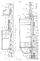
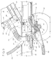
- trailer 10 comprising the invention is shown generally at 10 and has a kingpin 12 connected to the fifth wheel 14 of a tractor 16 for transport along a roadway as illustrated in Figure 1.
- Trailer 10 has a container generally indicated at 18 removably supported on a tiltable support frame generally indicated at 20 and mounted on trailer 10 for relative pivotal movement.
- Container 18 is preferably a standard container such as twenty (20) feet in length used in intermodal transportation such as in so-called COFC (container on flat car) service, container ships, or highway trailers.
- Container 18 has a bottom with corner fittings 22 which have suitable openings therein adapted to receive locking pins for releasably mounting container 18 onto support frame 20.
- a pair of rear end doors 24 on container 18 are mounted for movement between open and closed positions, and may be latched in a closed position.
- Container 18 is normally utilized for the transport of particulate lading, such as plastic pellets or the like, used in the manufacture of various plastic end products.
- the plastic particulate materials are normally transported from a plant where the plastic pellets or the like are manufactured, to a plant at another site where the plastic end products are manufactured from the plastic particulate materials. It is highly desirable that such plastic materials not be contaminated with foreign matter as the quality of the final manufactured product may be affected. Thus, it is desirable that the plastic lading be sealed from the environment after being loaded into container 18 until unloaded at an unloading site for conveyance to a storage facility where the plastic particulate material enters a manufacturing process for manufacture of a plastic end product.
- a plastic bag is normally placed within container 18 to receive the lading therein at the loading site, and the lading is unloaded by gravity from the plastic bag 19 as shown in Figures 8 and 9 at the unloading site as will be explained further.
- suitable transfer apparatus such as a crane or lift truck, for example, onto trailer 10 for transport to the unloading site.
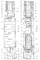
- Trailer 10 as shown particularly in Figures 5-7, has a so-called dropped deck to provide a relatively low center of gravity for the loaded container.
- the dropped or lower rear deck section is shown generally at 26 and the forward or upper deck section is shown generally at 28.
- Deck or trailer sections 26 and 28 form a vertical abutment 30 at their juncture for contacting the front end of container 18.
- Upper deck or trailer section 28 includes a pair of spaced longitudinally extending I-beams 32 connected by cross members 34.
- Rack members 36 extending outwardly from I-beams 32 provide supports for unloading equipment, such as connecting hoses 38 and the like.
- An air conduit shown at 40 has a removable end cap 42 and may be connected to a suitable alternate source of compressed air, such as an air compressor on tractor 16, at the unloading site for the pneumatic conveyance of the particulate lading from container 18 as will be explained further.
- a suitable alternate source of compressed air such as an air compressor on tractor 16
- Manually adjustable telescoping support legs generally indicated at 44 are secured to I-beams 32 for supporting the front end of trailer 10 when disconnected from tractor 16.
- Rear deck or trailer section 26 includes a pair of spaced longitudinally extending I-beams 46 connected by intermediate cross members 48 and a rear end cross member 50.
- a rear chassis supports the rear portion of trailer 10 and includes four pairs of spring brackets 52 secured to and extending downwardly from I-beams 46.
- Suitable leaf springs 54 are connected between spring brackets 52 for the resilient support of front axle 56, intermediate axle 58, and rear axle 60 equally spaced from each other a distance of around four and one-half (4-1/2) feet.
- Pneumatic tires 62 are mounted on the ends of axles 56, 58, and 60.
- Mounted adjacent opposite ends of rear end cross member 50 are a pair of hydraulically operated stanchions or vertical supports generally indicated at 64.
- Each stanchion 64 includes a hydraulic cylinder 66 an extensible piston rod 68 having a pivoted support plate 70 on its lower end for engaging a supporting surface to stabilize trailer 10 when unloading lading from container 18 at an unloading site.
- Rear trailer section 26 has a rearmost overhanging portion generally indicated at 72 which extends rearwardly from rearmost axle 60. Overhanging portion 72 extends a distance from rear axle 60 indicated at L in Figures 1 and 5 of around 5-1/2 feet. It is noted that the rear end of container 18 is positioned between intermediate axle 58 and rear axle 60.
- overhanging portion 72 of a substantial length be provided in order to provide adequate space for the unloading apparatus and workmen adjacent the rear end of container 18 during the unloading operation at the unloading site.
- Suitable cover plates 74 are provided over I-beams 46 of overhanging portion 72.
- overhanging portion 72 should be of a length of at least around 4 feet.
- Tilting container support frame generally indicated at 20 comprises a pair of spaced longitudinally extending channel-shaped members 78 connected at their ends by end frame members 80 and 82. End frame members 80 and 82 have corner supports 83 for securement of container 12 as shown in Figure 6.
- Cross members 84 are secured between side members 78 for reinforcement.
- an axle or shaft 86 extends between side members 78 adjacent end cross member 82 and is received within fixed tubular sleeve 76 for relative rotation. Suitable removable hubs 88 on the ends of shaft 86 secure shaft 86 within tubular sleeve 76 for pivotal movement.
- the other end of container support frame 20 has a pair of opposed brackets 90 secured to and extending forwardly of end frame member 80 as shown particularly in Figure 6.
- a hydraulic cylinder 92 has opposed stub shafts 93 at its lower end mounted for pivotal movement on brackets 90 thereby to permit pivoting of cylinder 92 relative to container 18 and support frame 20.
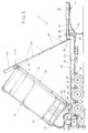
- Hydraulic cylinder 92 has a plurality of extensible telescoping sections 94 and the innermost section is pivotably mounted to a shaft 96 secured between I-beams 32. Upon supply of hydraulic fluid to cylinder 92 container support frame 20 is tilted to the position shown in Figures 5 and 9 for the gravity unloading of particulate lading from container 18.
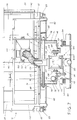
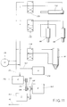
- a hopper is generally indicated at 100 into which lading flows by gravity from container 18 and is then conveyed pneumatically to a storage facility adjacent the unloading site, such as bins or silos, until needed in the production of end products, such as plastic end products.
- Hopper 100 has opposed bearing sleeves 102 mounting hopper 100 for limited pivotal movement in a vertical plane longitudinally of trailer 10 on opposed brackets 104 and 106 secured to I-beams 46 as shown particularly in Figure 7.
- Hopper 100 has an upper receiver 108 extending through an opening 109 in adjacent support plate 74 and pivoting with hopper 100 relative to container 18 to provide the desired angular relationship between container 18 and hopper 100 for adequate gravity flow of lading from container 18 to hopper 100 during the unloading operation.
- a hydraulic cylinder 110 pivotally supported to I-beams 46 has a piston rod 112 pivotally connected to bracket 114 on hopper 100 for pivotal movement of hopper 100 and receiver 108.
- a rotary valve generally indicated at 116 separates hopper 100 into an upper gravity feed portion 118 which includes receiver 108 and a lower pneumatic discharge portion 120 for pneumatic transport of the particulate lading.
- Rotary valve 116 provides a so-called "air-lock" between upper and lower hopper portions 118, 120 to maintain differential pressure between hopper portions 118 and 120.
- Rotary valve 116 has a body 122 with upper and lower flanges 124 and a rotor including vanes 126 secured to a shaft 128 for forming lading pockets 129 between vanes 126.
- a resilient wiper 130 is provided adjacent the top of rotary valve 116 to wipe any excess lading from the top of pockets 129.
- Shaft 128 fits within bearing sleeves 102 supported on brackets 106 on I-beams 46 as shown in Figure 7.
- a sprocket 132 is secured to an end of shaft and a sprocket chain 134 connects sprocket 132 with a suitable hydraulic motor 136 for rotation of rotary valve 116.
- a removable vertically extending support frame 140 having legs 142 is mounted within suitable openings in container support frame 20 for positioning at the rear end of container 18 after opening of one of the rear doors 24 on container 18.
- a suitable throttle valve assembly shown generally at 144 is mounted on vertical support frame 142 and has an inner end positioned within an opening 146 in a vertical backing member 148 at the rear of container 18.
- Throttle valve assembly 144 includes a manually operated butterfly valve shown at 150 which controls the gravity flow of lading from container 18.
- a flexible sleeve 152 is connected at the unloading site between receiver 108 and throttle valve assembly 144.
- Receiver 108 includes a branch line 154 and a flexible hose 156 is connected between branch line 154 and the upper end of container 18 to provide a source of atmospheric air to the interior of container 18 to aid in collapsing of the plastic liner for the particulate lading within container 18 as the lading is unloaded.
- a detachable flexible hose 158 is connected at the unloading site between one end of lower pneumatic hopper portion 120 and line 40. Air is supplied to line 40 from a suitable source of compressed gas such as an air compressor and blower shown generally at 160 on tractor 16. It may be desirable under some conditions to mount the compressor and blower on trailer 10 for operation independently of tractor 16.
- a flexible unloading hose 162 is connected to the other side of pneumatic hopper portion 120 for conveying the lading to the storage facility.
- Hopper 100 which includes receiver 108, rotary valve 116, and lower pneumatic hopper portion 120 is supported for pivotal movement on bearing sleeves 102 along the axis of shaft 128 of rotary valve 116.
- detachable lading conduit or hose 152 between receiver 108 and container 18 at the unloading site so that an adequate height above receiver 108 is obtained for gravity unloading when container 18 is tilted, it is desirable to be able to move the upper end of receiver 108 toward and away from container 18 in a direction longitudinally of trailer 10.
- hopper 100 is mounted for pivotal movement about shaft 128 relative to trailer 10.
- hopper 100 For initially connecting flexible lading hose 152 at the unloading site prior to tilting of support frame 20, hopper 100 is pivoted to move receiver 118 toward container 18 such as five degrees (5°) from a vertical position. Then, after connection of lading hose 118 and during tilting of container 18 and support frame 20 an amount such as shown at angle A in Figure 9 of around thirty-five degrees (35°) which is greater than the angle of repose of the lading, hopper 100 and receiver 108 are pivoted in a direction away from container 18 to maintain a desired angular relation between container 18 and receiver 108 for the gravity flow of lading from container 18 into hopper 100.
- Pivot 86 is positioned between axles 58 and 60 at a horizontal distance D closer to axle 60 than axle 58 in order to provide the proper load distribution for a maximum lading weight of around 43,000 to 45,000 pounds in container 18 and to provide adequate support for loaded container 18 when tilted to a maximum angle A of around fifty (50) degrees such as shown in Figure 5.
- Distance D is preferably around five (5) inches, but may vary between around two (2) inches and twenty-four (24) inches with satisfactory results in the design of trailer 10 according to European specifications while utilizing three rear axles as shown at 56, 58, and 60.
- hopper 100 is mounted rearwardly of rearmost axle 60 between I-beams 46 on overhanging trailer portion 72 a horizontal distance D1 of around fifteen (15) inches from rearmost axle 60.
- Distance D1 may vary between around six (6) inches and thirty (30) inches with satisfactory results.
- the pivot axis 128 of hopper 100 is at a height H below pivot 86 of container support frame 20 and at a height H1 above axle 60.
- Height H is preferably around twelve (12) inches but may be of a range between around six (6) inches and twenty (20) inches.
- Height H1 is preferably around twelve (12) inches but may be of a range between around six (6) inches and twenty (20) inches to provide a satisfactory design for trailer 10.
- a fast gravity flow of lading is maintained between container 18 and receiver 108 for feeding the particulate lading to rotary valve 116 and to lower pneumatic hopper portion 120 for pneumatic conveyance to a suitable storage site or the like.
- a power drive means is illustrated at 164 comprising a gasoline engine mounted on trailer 10 between I-beams 46 forwardly of axle 56 and having a drive shaft 166 extending therefrom.
- a pulley 168 is connected by a drive belt 170 to a hydraulic pump 172 to supply hydraulic fluid from a reservoir 174 through supply line 176 to (1) hydraulic motor 136 for rotating shaft 128 and rotary valve 116, (2) hydraulic cylinder 110 for pivoting hopper 100 and receiver 118 about shaft 128, (3) hydraulic cylinder 66 for raising and lowering stanchions 64, and (4) cylinder 92 for raising and lowering container support frame 20 and container 18.
- Suitable three way valves 178 are provided to control the flow of hydraulic fluid to cylinders 66, 92, and 110.
- a return line 180 returns hydraulic fluid to reservoir 174.
- a drive sprocket 182 on shaft 166 is connected to air compressor 160 and a suitable blower for air compressor 160 supplies compressed air through line 42 and hose 158 to lower pneumatic hopper portion 120 for entraining particulate lading therein for delivery through discharge hose 162 to the storage facility.
- a suitable control box is provided at 186 on overhanging trailer portion 72 for operation of the power equipment and controls from a manual control panel shown at 188 in Figure 3.
- a trailer 10 having a length of around thirty-nine (39) feet was provided with axles 56, 58, and 60 spaced from each other a distance of four and one-half (4-1/2) feet.
- the overhanging portion 72 had a length L of around six (6) feet from the centerline of the rearmost axle 60.
- Height H was twelve (12) inches and height H1 was twelve (12) inches.
- Distance D was five (5) inches and distance D1 was fifteen (15) inches.
- the total gross weight permitted under European specifications is 83,900 provides for the tractor and trailer transporting a loaded container.
- the tractor has a weight of around 17,000 pounds, the trailer a weight of around 15,000 pounds, and the container of around twenty (20) feet in length has an unloaded weight of 5,000 pounds.
- the container was loaded with polyethylene plastic pellets having a weight of around 45,000 pounds.
- Such a design for a trailer in accordance with European specifications for the transport of particulate lading in a container for gravity unloading of the particulate material, such as plastic pellets, into a high velocity air stream at an unloading site has been found to be highly economical for the transport of a maximum lading weight between 43,000 to 46,000 pounds.
- a workman In operation at an unloading site, a workman unlatches one rear door 24 to expose discharge opening 146 in backing member 148. Then, support frame 140 is mounted within openings in support frame 20 adjacent the open door 24 and throttle valve assembly 144 is mounted on frame 140. In this position, hopper 100 is pivoted to move receiver 108 toward container 18. Then, hose 152 is connected along with hoses 156 and 158 and hose 162 from lower pneumatic hopper portion 120. To commence the flow of lading from container 18, the plastic bag or liner in container 18 is slit by a workman and lading then enters the valve body with butterfly valve 150 being closed. Next engine 164 is started to drive compressor 160 when mounted on trailer 10 and hydraulic pump 172.
- Stanchions 64 are lowered by actuation of cylinders 66 to stabilize trailer 10 during the unloading operation. Fluid is supplied to cylinder 92 for raising container support frame 20 and loaded container 18 thereon to an angle two (2) or three (3) degrees above the angle of repose of the lading. Hopper 100 and receiver 108 are tilted rearwardly by actuation of cylinder 110 upon tilting of support frame 18 in order to maintain the desired angular relationship between container 18 and receiver 108.
- Butterfly valve 150 is manually opened a desired amount to supply a maximum amount of lading to rotary valve 116 for feeding into the high velocity air stream for discharge. Thus, container 18 is unloaded in a minimum of time.
- Compressed air is delivered at a pressure of around four (4) psi at seven hundred cubic feet per minute (CFM) to provide an air velocity of sixty five hundred (6,500) feet per minute through conduit 40, hose 158, lower hopper portion 120 and discharge conduit 162.
- CFM cubic feet per minute
- a neglible amount of lading, less than ten (10) pounds remain in container 18 after unloading.
- minimal unloading time is required and minimal loss of lading is provided by the transportation system utilizing the trailer comprising the present invention and the unloading method described.
Landscapes
- Engineering & Computer Science (AREA)
- Transportation (AREA)
- Mechanical Engineering (AREA)
- Filling Or Emptying Of Bunkers, Hoppers, And Tanks (AREA)
- Transition And Organic Metals Composition Catalysts For Addition Polymerization (AREA)
- Vehicle Cleaning, Maintenance, Repair, Refitting, And Outriggers (AREA)
- Furnace Charging Or Discharging (AREA)
- Control And Other Processes For Unpacking Of Materials (AREA)
- Crystals, And After-Treatments Of Crystals (AREA)
Applications Claiming Priority (2)
| Application Number | Priority Date | Filing Date | Title |
|---|---|---|---|
| US619920 | 1990-11-30 | ||
| US07/619,920 US5096336A (en) | 1990-11-30 | 1990-11-30 | Trailer for transporting containers |
Publications (3)
| Publication Number | Publication Date |
|---|---|
| EP0488162A2 true EP0488162A2 (de) | 1992-06-03 |
| EP0488162A3 EP0488162A3 (en) | 1992-10-28 |
| EP0488162B1 EP0488162B1 (de) | 1996-08-21 |
Family
ID=24483862
Family Applications (1)
| Application Number | Title | Priority Date | Filing Date |
|---|---|---|---|
| EP91120177A Expired - Lifetime EP0488162B1 (de) | 1990-11-30 | 1991-11-26 | Anhänger für Containertransport |
Country Status (6)
| Country | Link |
|---|---|
| US (1) | US5096336A (de) |
| EP (1) | EP0488162B1 (de) |
| AT (1) | ATE141557T1 (de) |
| CA (1) | CA2055406C (de) |
| DE (1) | DE69121529T2 (de) |
| MX (1) | MX9101990A (de) |
Cited By (2)
| Publication number | Priority date | Publication date | Assignee | Title |
|---|---|---|---|---|
| EP0873953A1 (de) * | 1997-04-26 | 1998-10-28 | Degussa Aktiengesellschaft | Entleervorrichtung für Bulk-Container für teilchenförmige Schüttgüter und seine Verwendung |
| CN102923036A (zh) * | 2012-10-26 | 2013-02-13 | 青特集团有限公司 | 双集装箱半挂后卸车 |
Families Citing this family (19)
| Publication number | Priority date | Publication date | Assignee | Title |
|---|---|---|---|---|
| US5378047A (en) * | 1992-06-15 | 1995-01-03 | Intermodal Container Systems | Container unloading assembly for gravity unloading of particulate material |
| US5482356A (en) * | 1994-03-31 | 1996-01-09 | Goodson Building Systems, Inc. | Rear dump trailer |
| US5653469A (en) | 1995-05-25 | 1997-08-05 | Wade; Sidney Allen | Mobile storage tank |
| US5975642A (en) * | 1997-11-12 | 1999-11-02 | Eastman Chemical Company | System for transporting and unloading dry chemicals |
| US6409274B1 (en) | 2000-07-31 | 2002-06-25 | Intermodal Container Systems | Apparatus and method for unloading particulate material from containers |
| CA2423321C (en) * | 2000-10-24 | 2010-06-08 | E.I. Du Pont De Nemours And Company | A system and method for unloading bulk powder from large bulk containers |
| WO2003077635A2 (en) | 2002-03-15 | 2003-09-25 | Finn Corporation | Bulk material discharge assembly with feeding apparatus |
| US7275893B2 (en) * | 2003-03-19 | 2007-10-02 | Finn Corporation | Apparatuses and methods for dispensing materials |
| US20080025138A1 (en) * | 2006-07-28 | 2008-01-31 | Cherry Jason E | Mortor mixing stand |
| DE102007032017B4 (de) * | 2007-05-16 | 2011-01-27 | Bayer Materialscience Ag | Verfahren zum Befüllen und Entleeren von Transport-Containern mit Kunststoffgranulaten |
| US8100220B2 (en) * | 2008-03-28 | 2012-01-24 | Rexius Forest By-Products, Inc. | Vehicle having auxiliary steering system |
| US9051137B2 (en) | 2010-12-03 | 2015-06-09 | Vincent R. Meier | Cement silo loading system |
| EP2548766A1 (de) | 2011-07-22 | 2013-01-23 | Solvay Sa | Entladevorrichtung, Verfahren und entladenes Pulver |
| EP2607275B1 (de) * | 2011-12-20 | 2018-01-31 | Rainer Dirnhofer | System zum gravitativen Entleeren eines Schüttgutbehälters |
| US9743579B2 (en) | 2013-12-09 | 2017-08-29 | Cnh Industrial America Llc | Weight distribution controlled by sectioned product container of agricultural application implements |
| US9725025B2 (en) | 2014-02-27 | 2017-08-08 | Vincent R. Meier | Unloading apparatus for dry bulk material |
| US10815081B2 (en) * | 2018-04-03 | 2020-10-27 | Mac Trailer Manufacturing, Inc. | Trailer having increased ground clearance |
| US11267663B2 (en) | 2019-01-15 | 2022-03-08 | Quickthree Technology, Llc | Bottom dump pneumatic material handling system |
| DE102019115196A1 (de) * | 2019-06-05 | 2020-12-10 | Wirtgen Gmbh | Silofahrzeug, Fördersystem für ein Silofahrzeug, Arbeitszug sowie Verfahren zum Fördern von Bindemittel für einen Arbeitszug |
Family Cites Families (10)
| Publication number | Priority date | Publication date | Assignee | Title |
|---|---|---|---|---|
| US2513757A (en) * | 1947-10-11 | 1950-07-04 | Speaker John Walter | Patch unit for vulcanizers |
| US2487503A (en) * | 1948-02-10 | 1949-11-08 | Lloyd E Witter | Road-sanding machine |
| GB1029909A (en) * | 1964-07-23 | 1966-05-18 | Ass Portland Cement | Pressure discharge container for powder in bulk |
| NL7812680A (nl) * | 1978-12-30 | 1980-07-02 | Stamicarbon | Werkwijze voor het lossen van poedervormige melamine uit een container, container geschikt voor het transport van melamine en hopper geschikt voor deze werkwijze. |
| SE7901709L (sv) * | 1979-02-26 | 1980-08-27 | Boliden Ab | Forfarande for att ur transportkerl, foretredesvis av containerstorlek, tomma och uppsamla enhetliga satser av en korn- eller stoftformig produkt utan nedstoftning av omgivningen samt anordning for genomforande av forfa |
| GB2046957A (en) * | 1979-03-21 | 1980-11-19 | Edbro Holdings | Vehicle stability control system |
| US4247228A (en) * | 1979-04-02 | 1981-01-27 | Morton E. Gray | Dump truck or trailer with pneumatic conveyor |
| US4474526A (en) * | 1981-10-27 | 1984-10-02 | Eugene A. Le Boeuf | Lift bed dumper trailer |
| JPS6112446A (ja) * | 1984-06-27 | 1986-01-20 | Kongo Seisakusho:Kk | 粉粒体運搬ダンプ車の空気圧送装置 |
| US4875811A (en) * | 1987-02-02 | 1989-10-24 | Intermodal Container Systems | Apparatus and method for transporting and unloading containers |
-
1990
- 1990-11-30 US US07/619,920 patent/US5096336A/en not_active Expired - Fee Related
-
1991
- 1991-11-08 MX MX9101990A patent/MX9101990A/es unknown
- 1991-11-13 CA CA002055406A patent/CA2055406C/en not_active Expired - Fee Related
- 1991-11-26 DE DE69121529T patent/DE69121529T2/de not_active Expired - Fee Related
- 1991-11-26 AT AT91120177T patent/ATE141557T1/de not_active IP Right Cessation
- 1991-11-26 EP EP91120177A patent/EP0488162B1/de not_active Expired - Lifetime
Cited By (3)
| Publication number | Priority date | Publication date | Assignee | Title |
|---|---|---|---|---|
| EP0873953A1 (de) * | 1997-04-26 | 1998-10-28 | Degussa Aktiengesellschaft | Entleervorrichtung für Bulk-Container für teilchenförmige Schüttgüter und seine Verwendung |
| US5988436A (en) * | 1997-04-26 | 1999-11-23 | Degussa Aktiengesellschaft | Discharge device for bulk containers for particulate bulk materials and its use |
| CN102923036A (zh) * | 2012-10-26 | 2013-02-13 | 青特集团有限公司 | 双集装箱半挂后卸车 |
Also Published As
| Publication number | Publication date |
|---|---|
| CA2055406C (en) | 1995-02-14 |
| US5096336A (en) | 1992-03-17 |
| DE69121529T2 (de) | 1997-03-27 |
| DE69121529D1 (de) | 1996-09-26 |
| MX9101990A (es) | 1993-01-01 |
| ATE141557T1 (de) | 1996-09-15 |
| EP0488162B1 (de) | 1996-08-21 |
| CA2055406A1 (en) | 1992-05-31 |
| EP0488162A3 (en) | 1992-10-28 |
Similar Documents
| Publication | Publication Date | Title |
|---|---|---|
| EP0488162B1 (de) | Anhänger für Containertransport | |
| US4875811A (en) | Apparatus and method for transporting and unloading containers | |
| US6503042B2 (en) | Bulk material handling system | |
| US4567820A (en) | Silo bag packing machine | |
| US3792790A (en) | Transportable bulk-material handling apparatus | |
| US4722655A (en) | Bulk storage bin for freight vehicle or other storage facility | |
| US7090066B2 (en) | Unloading system for particulate material | |
| US8931995B2 (en) | Seed cart | |
| US20160244268A1 (en) | Mobile material elevating system | |
| US6623234B1 (en) | Non-linear sided trailer with continuous conveyor bed | |
| CA1216470A (en) | Flexible bulk container | |
| US20060239806A1 (en) | Mobile material placer and conveying system and method of placing and conveying material utilizing the same | |
| US5378047A (en) | Container unloading assembly for gravity unloading of particulate material | |
| US9975712B2 (en) | Portable drive-over conveyor system usable for unloading belly dump trucks with multiple discharges and for simultaneously unloading more than one truck | |
| CA2419893A1 (en) | Method and apparatus for supplying bulk product to an end user | |
| US20050123385A1 (en) | Unloading system for particulate material | |
| US4861215A (en) | Bulk storage bin with pneumatically assisted discharge | |
| EP1434475B1 (de) | Verfahren zum transport und füllen von frachtcontainern | |
| US5520495A (en) | Method and means for filling field planters from bulk seed containers | |
| US4854801A (en) | Bulk storage bin with pneumatically assisted discharge | |
| US20120321421A1 (en) | Apparatus and method for conveying bulk materials | |
| US6409274B1 (en) | Apparatus and method for unloading particulate material from containers | |
| US6238162B1 (en) | Transportable apparatus for unloading material from a dump truck | |
| US4019284A (en) | Self-contained sandblasting apparatus | |
| US3819070A (en) | Bulk material handling system |
Legal Events
| Date | Code | Title | Description |
|---|---|---|---|
| PUAI | Public reference made under article 153(3) epc to a published international application that has entered the european phase |
Free format text: ORIGINAL CODE: 0009012 |
|
| AK | Designated contracting states |
Kind code of ref document: A2 Designated state(s): AT BE CH DE DK ES FR GB GR IT LI LU NL SE |
|
| PUAL | Search report despatched |
Free format text: ORIGINAL CODE: 0009013 |
|
| AK | Designated contracting states |
Kind code of ref document: A3 Designated state(s): AT BE CH DE DK ES FR GB GR IT LI LU NL SE |
|
| 17P | Request for examination filed |
Effective date: 19930406 |
|
| 17Q | First examination report despatched |
Effective date: 19940803 |
|
| GRAH | Despatch of communication of intention to grant a patent |
Free format text: ORIGINAL CODE: EPIDOS IGRA |
|
| GRAH | Despatch of communication of intention to grant a patent |
Free format text: ORIGINAL CODE: EPIDOS IGRA |
|
| GRAA | (expected) grant |
Free format text: ORIGINAL CODE: 0009210 |
|
| AK | Designated contracting states |
Kind code of ref document: B1 Designated state(s): AT BE CH DE DK ES FR GB GR IT LI LU NL SE |
|
| PG25 | Lapsed in a contracting state [announced via postgrant information from national office to epo] |
Ref country code: IT Free format text: LAPSE BECAUSE OF FAILURE TO SUBMIT A TRANSLATION OF THE DESCRIPTION OR TO PAY THE FEE WITHIN THE PRE;WARNING: LAPSES OF ITALIAN PATENTS WITH EFFECTIVE DATE BEFORE 2007 MAY HAVE OCCURRED AT ANY TIME BEFORE 2007. THE CORRECT EFFECTIVE DATE MAY BE DIFFERENT FROM THE ONE RECORDED.SCRIBED TIME-LIMIT Effective date: 19960821 Ref country code: NL Free format text: LAPSE BECAUSE OF FAILURE TO SUBMIT A TRANSLATION OF THE DESCRIPTION OR TO PAY THE FEE WITHIN THE PRESCRIBED TIME-LIMIT Effective date: 19960821 Ref country code: CH Effective date: 19960821 Ref country code: LI Effective date: 19960821 Ref country code: FR Effective date: 19960821 Ref country code: AT Effective date: 19960821 Ref country code: GR Free format text: LAPSE BECAUSE OF FAILURE TO SUBMIT A TRANSLATION OF THE DESCRIPTION OR TO PAY THE FEE WITHIN THE PRESCRIBED TIME-LIMIT Effective date: 19960821 Ref country code: ES Free format text: THE PATENT HAS BEEN ANNULLED BY A DECISION OF A NATIONAL AUTHORITY Effective date: 19960821 Ref country code: DK Effective date: 19960821 |
|
| REF | Corresponds to: |
Ref document number: 141557 Country of ref document: AT Date of ref document: 19960915 Kind code of ref document: T |
|
| REF | Corresponds to: |
Ref document number: 69121529 Country of ref document: DE Date of ref document: 19960926 |
|
| PG25 | Lapsed in a contracting state [announced via postgrant information from national office to epo] |
Ref country code: SE Effective date: 19961121 |
|
| PG25 | Lapsed in a contracting state [announced via postgrant information from national office to epo] |
Ref country code: LU Free format text: LAPSE BECAUSE OF NON-PAYMENT OF DUE FEES Effective date: 19961130 |
|
| EN | Fr: translation not filed | ||
| NLV1 | Nl: lapsed or annulled due to failure to fulfill the requirements of art. 29p and 29m of the patents act | ||
| REG | Reference to a national code |
Ref country code: CH Ref legal event code: PL |
|
| PLBE | No opposition filed within time limit |
Free format text: ORIGINAL CODE: 0009261 |
|
| STAA | Information on the status of an ep patent application or granted ep patent |
Free format text: STATUS: NO OPPOSITION FILED WITHIN TIME LIMIT |
|
| 26N | No opposition filed | ||
| PGFP | Annual fee paid to national office [announced via postgrant information from national office to epo] |
Ref country code: GB Payment date: 19991124 Year of fee payment: 9 |
|
| PGFP | Annual fee paid to national office [announced via postgrant information from national office to epo] |
Ref country code: BE Payment date: 20000121 Year of fee payment: 9 |
|
| PGFP | Annual fee paid to national office [announced via postgrant information from national office to epo] |
Ref country code: DE Payment date: 20001102 Year of fee payment: 10 |
|
| PG25 | Lapsed in a contracting state [announced via postgrant information from national office to epo] |
Ref country code: GB Free format text: LAPSE BECAUSE OF NON-PAYMENT OF DUE FEES Effective date: 20001126 |
|
| PG25 | Lapsed in a contracting state [announced via postgrant information from national office to epo] |
Ref country code: BE Free format text: LAPSE BECAUSE OF NON-PAYMENT OF DUE FEES Effective date: 20001130 |
|
| BERE | Be: lapsed |
Owner name: INTERMODAL CONTAINER SYSTEMS Effective date: 20001130 |
|
| GBPC | Gb: european patent ceased through non-payment of renewal fee |
Effective date: 20001126 |
|
| PG25 | Lapsed in a contracting state [announced via postgrant information from national office to epo] |
Ref country code: DE Free format text: LAPSE BECAUSE OF NON-PAYMENT OF DUE FEES Effective date: 20020702 |