EP0488085B1 - Greifereinrichtung von einer Übertragungseinheit - Google Patents
Greifereinrichtung von einer Übertragungseinheit Download PDFInfo
- Publication number
- EP0488085B1 EP0488085B1 EP91119979A EP91119979A EP0488085B1 EP 0488085 B1 EP0488085 B1 EP 0488085B1 EP 91119979 A EP91119979 A EP 91119979A EP 91119979 A EP91119979 A EP 91119979A EP 0488085 B1 EP0488085 B1 EP 0488085B1
- Authority
- EP
- European Patent Office
- Prior art keywords
- nipping
- drive
- rotating element
- pivoting levers
- pivoting
- Prior art date
- Legal status (The legal status is an assumption and is not a legal conclusion. Google has not performed a legal analysis and makes no representation as to the accuracy of the status listed.)
- Expired - Lifetime
Links
- 238000012546 transfer Methods 0.000 title claims description 109
- 239000000463 material Substances 0.000 claims description 16
- 230000001105 regulatory effect Effects 0.000 claims description 3
- 230000000670 limiting effect Effects 0.000 claims description 2
- 238000000926 separation method Methods 0.000 description 11
- 210000000078 claw Anatomy 0.000 description 9
- 230000007246 mechanism Effects 0.000 description 9
- 238000000034 method Methods 0.000 description 5
- 230000008569 process Effects 0.000 description 5
- 230000009471 action Effects 0.000 description 3
- 230000008859 change Effects 0.000 description 3
- 238000012986 modification Methods 0.000 description 3
- 230000004048 modification Effects 0.000 description 3
- 239000000853 adhesive Substances 0.000 description 2
- 230000001070 adhesive effect Effects 0.000 description 2
- 238000013459 approach Methods 0.000 description 2
- 230000015572 biosynthetic process Effects 0.000 description 2
- 230000000694 effects Effects 0.000 description 2
- 238000007373 indentation Methods 0.000 description 2
- 230000000717 retained effect Effects 0.000 description 2
- 238000007796 conventional method Methods 0.000 description 1
- 238000010168 coupling process Methods 0.000 description 1
- 238000005859 coupling reaction Methods 0.000 description 1
- 230000007423 decrease Effects 0.000 description 1
- 230000014759 maintenance of location Effects 0.000 description 1
- 238000004519 manufacturing process Methods 0.000 description 1
- 230000036961 partial effect Effects 0.000 description 1
- 238000003825 pressing Methods 0.000 description 1
- 230000002265 prevention Effects 0.000 description 1
- 230000009467 reduction Effects 0.000 description 1
- 230000002829 reductive effect Effects 0.000 description 1
- 230000000284 resting effect Effects 0.000 description 1
- 238000004804 winding Methods 0.000 description 1
Images


Classifications
-
- B—PERFORMING OPERATIONS; TRANSPORTING
- B65—CONVEYING; PACKING; STORING; HANDLING THIN OR FILAMENTARY MATERIAL
- B65H—HANDLING THIN OR FILAMENTARY MATERIAL, e.g. SHEETS, WEBS, CABLES
- B65H5/00—Feeding articles separated from piles; Feeding articles to machines
- B65H5/08—Feeding articles separated from piles; Feeding articles to machines by grippers, e.g. suction grippers
- B65H5/12—Revolving grippers, e.g. mounted on arms, frames or cylinders
Definitions
- the present invention relates to a nipping device, more particularly to a nipping device which retains a printing sheet against the outer surface of a transfer unit, and separates it therefrom as well.
- a transfer drum comprising the principal component of a transfer unit is provided opposite a photoconductor drum in a full-color copying machine.
- a printing sheet is wound onto the circumferential surface of the transfer drum, wherein images developed on the photoconductor drum are transferred onto the printing sheet.
- the transfer drum is provided with a nipping device which is employed both to wind a printing sheet onto the transfer drum and to separate the printing sheet therefrom.
- the European Patent Application EP-A 0 299 645 discloses a sheet clamping system of the type in question.
- the clamping system comprises a pair of clamping bars for releasably clamping the leading and trailing edges of a sheet onto the periphery of a drum.
- Means are provided for retaining each of the clamping bars in their respective sheet clamping positions against axially outward movement due to centrifugal force arising upon rotation of the drum.
- Pivotal means are provided for each clamping bar, which comprise a pivotal bell crank located within the drum and having a claw projecting from the drum to engage and retain the clamping bar.
- Fig. 13 shows another conventional nipping device, comprising lift members 71 having their tips inserted under a printing sheet 70, and a nipper 72 employed in conjunction with a stay of the transfer drum (not shown), to retain the printing sheet 70.
- a rotator shaft 73 is provided along the pivot axis of the lift members 71 and nipper 72, parallel to the axis of the transfer unit drum. Extending radially from the rotator shaft 73, are pins (not shown) which, as the rotator shaft 73 turns, come into lifting contact with the lift members 71 and nipper 72.
- One end 73a of the rotator shaft 73 forms a crank which rides on the outer surface of a cam 74 mounted on a rotator member within the transfer drum.
- Torsion springs 75 are disposed on the lift members 71 and nipper 72, whereby the lift members 71 and nipper 72 are impelled inward (toward the inside of the transfer drum).
- the lift members 71, nipper 72, rotator shaft 73 and torsion springs 75 are provided in the rotational element of the transfer unit.
- Separation claws 76 are fixed to a frame of the copying machine, adjacent to the transfer unit.
- the crank portion 73a of the rotating shaft 73 comes into contact with a cam different from the cam corresponding to the sheet nipping position, and the lift members 71 and nipper 72 are raised outward in the same manner as previously described. Consequently, the end of the printing sheet 70 is sufficiently separated from the circumferential surface of the transfer drum, to allow it to catch on the separation claws 76. As the transfer drum rotates further, the printing sheet 70 is transferred along the separation claws 76 to an adjoining transport system.
- the conventional nipping device as described above employs torsion springs for impelling the lift members and nippers inward, and it is difficult to set and/or regulate the impelling forces of such springs, which must then of necessity be on the overly-powerful side, the drive system of the transfer drum is liable to receive excessive loads. Furthermore, since four sets of mechanisms as shown in Fig. 13 are normally provided in the transfer drum, a total of twelve torsion springs are thus required, and the tendency to excess load on the drive system is multiplied.
- An object of the present invention is to facilitate the setting of the impellent force of nipping device nippers in a transfer unit and to prevent the application of excess load to the transfer unit drive system.
- Another object is to enable the smooth separation of a printing sheet from the transfer unit.
- Still another object of the present invention is to prevent abrupt changes in load on the drive system to a transfer unit during the opening and closing operation of a nipping device therein.
- a further object is to ensure accuracy in the nipping operation of a transfer unit nipping device.
- a nipping device is provided as defined in claim 1.
- Embodiments of the invention are given in claims 2 to 19.
- the nipper mechanism is rotatable and is disposed in the circumferential surface of the rotating element, and retains the leading edge of a printing sheet fed thereto.
- the pivoting lever element is disposed within the rotating element, and comprises levers which pivot on axes which intersect the circumferential surface of the transfer unit, whereby the nipper mechanism is opened and closed so as to retain the printing sheet against the transfer unit and to separate it there from accordingly.
- a drive cam element comes into pivotal association with the pivoting levers.
- the pivoting levers are preferably under the retentive agency of tension springs.
- tension springs In contrast to the conventional device in which the lift and nipping members pivot on an axis parallel to the axis of the transfer drum, it is possible to impel elastically the pivoting levers a direction of uniformity.
- the tension springs to the pivoting levers facilitates setting the elastic force of the springs to that required to prevent the application of excess load to the driving system of the transfer unit.
- the nipping device includes a plurality of nippers and a plurality of lift regulators.
- the nippers are openably disposed on the circumferential surface of the rotating element, and hold the feed-leading edge of a printing sheet.
- the lift regulators regulate the lift of the nippers away from the outer surface of the rotating device when the nippers are in an open position.
- the leading edge of the printing sheet is either nipped against the circumferential surface of the rotating device, or is released therefrom.
- the lift regulators When the nippers are in the open position, the extent of lift of the nippers away from the circumferential surface of the transfer unit is regulated by the lift regulators.
- each nipper is independently regulated by the lift regulators, the variance in the lift extent of the nippers necessary to smoothly separate the printing sheet from the rotating device can be effected.
- the nipping device includes at least one pair of nipper mechanisms, a pivoting lever device having at least a pair of pivoting levers, and drive cams.
- the pivoting levers of the pair each have one end supported by the rotating element pivotally on an axis intersecting the circumferential surface of the rotating device.
- the remaining ends face each other, and are driven into positions apart from each other as they open and close the nipper mechanisms.
- the drive cams are disposed so as to come into driving contact with the facing ends of the pivoting levers, and are slidable in a direction alongside the rotation axis of the rotating element.
- the pivoting levers are under the retentive agency of tension springs which can be utilized in the same manner as described above, making it possible to achieve reduction in the load applied to the drive system of the transfer unit.
- the drive cans are slidable, even if they deviate from the center between the facing ends of the pivoting levers, the positioning of the drive cams is automatically corrected when they come into contact with the corresponding facing ends of the pivoting levers. Thus, accuracy in the nipping operation of this nipping device is ensured.
- Fig. 1 is illustrative of a full-color copying apparatus to which a transfer unit employing a nipping device according to the first embodiment of the present invention may be applied.
- FIG. 1 An original retainer 2 is disposed in the upper portion of the copying machine body 1, and an original cover 3 is openably mounted on top of the original retainer 2.
- a copy tray 4 and a plurality of feed cassettes 5 are provided in the left portion of the machine body 1 in the figure, and a bypass feed tray 6 is provided in the right portion thereof.
- a photoconductor drum 7 is disposed within the machine body 1.
- a charger, a transfer unit, a sheet separation device and a clearing unit, as well as a developing section including vertically arranged developing units 10, 11, 12 and 13, are disposed in the region of the photoconductor drum 7.
- the developing units consist of magenta developing unit 10, cyan developing unit 11, yellow developing unit 12, and black developing unit 13 in order descending from the uppermost one.
- These developing units 10 to 13 are supported by a movable frame 9, which is vertically conveyed by means of a moving mechanism 16.
- the moving mechanism 16 includes a stepping motor, bevel gears 17 and 18 connected to the stepping motor, a ball screw 19 fixed to the bevel gear 18 and extending vertically, and a nut 20 fixed to the movable frame 9 which mates with the ball screw 19.
- a transfer drum 21 is disposed adjacent to the photoconductor drum 7.
- a laser unit 22 is disposed over the photoconductor drum 7.
- the laser unit 22 emits a laser beam which is shone upon the upper surface of the photoconductor drum 7.
- An image reader 23 comprising charge-coupling devices (CCDs) is disposed under the original retainer 2.
- the image reader 23 is driven to reciprocate horizontally in the figure, so as to scan an original placed on the original retainer 2.
- the image information thus obtained by the image reader 23 is supplied as an electric signal to the laser unit 22.
- Sheet transport paths 24 and 25 are disposed under the transfer drum 21 and between the feed cassette 5 and the bypass feed tray 6.
- the sheet transport paths 24 and 25 each include feed guides and feed rollers.
- a discharged-sheet transport system 26 and an image fixing unit 27 are provided between the transfer drum 21 and the copy tray 4.
- Separation claws 28 for separating a printing sheet from the transfer drum 21, on which it is retained during an image transfer process, are provided between the transfer drum 21 and the discharged-sheet transport system 26.
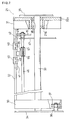
- Figs. 2 to 5 show the detailed structure of the transfer drum 21.
- the transfer drum 21 is supported at both ends by rims 30 and 31.
- a stay 32 couples the two rims 30 and 31.
- a transfer drum shaft 33 penetrates the centers of the rims 30 and 31, and the ends of the drum shaft 33 are fixed to frames 34 and 35, respectively.
- the rim 30 is rotatably supported on bearings 37, which are disposed at predetermined intervals along the circumference of the rim 30 and are attached to the frame 34 by means or pins 36.
- the rim 31 includes hub 31a, which is rotatably supported by the drum shaft 33 through bearings 38.
- a geared portion 31b is formed along the circumference of the rim 31, and is in engagement with a corresponding geared portion (not shown) of the photoconductor drum 7.
- nippers 40 are provided on the outer surface of the stay 32, and pivoting levers 41 and 42 are provided on the inner surface of the stay 32.
- a structure which is the same as that shown in Fig. 3 adjacent to rim 31 is also provided adjacent to rim 30.
- pivoting levers corresponding to the respective nippers 40 being provided as well.
- each nipper 40 consists of a relatively wide sleet retainer tab 40a along its middle portion, sheet lifting portions 40b formed at either side of the sheet retainer tab 40a and sloping downward from it, and a support portion 40c which forms the base of the portions 40a and 40b.
- the support portion 40c of each nipper 40 is pivotally supported by means of a pin within a notch formed in the stay 32.
- An engaging portion 40d projects from the support portion 40c beyond the stay 32 toward the interior of the transfer drum 21.
- each of the pivoting levers 41 and 42 is pivotally mounted on the stay 32 through a pin 43.
- the other ends of the levers 41 and 42 constitute oblique surfaces 41b and 42b which face each other at a predetermined spacing.
- Pins 44 projecting outward from the outer surfaces of the levers 41 and 42 are inserted in arced guide slots 32a and 32b formed in the stay 32.
- One end of each of tension springs 45 is attached to a corresponding pin 44, wherein the opposite end of each is attached to the stay 32.
- the pivoting levers 41 and 42 are pivotal on the axes (pins 43) perpendicular to the corresponding tangent to the outer surface of the transfer drum 21.
- L-shaped catches 41a and 42a project laterally from each of the pivoting levers 41 and 42.
- the engaging portions 40d of the nippers 40 engage with these portions 41a and 42a.
- the nippers 40 are opened and closed by the pivoting of the pivoting levers 41 and 42.
- the guide slots 32a and 32b formed in the stay 32 should be of at least the minimum arc length to permit the corresponding opening angle ⁇ .
- the guide slots 32a and 32b are of such length as to allow the nippers 40 to open more widely than the angle ⁇ .
- the engaging portions 40d of the nippers 40 disengage from the catches 41a and 42a of the pivoting levers 41 and 42, such that they can be set onto the catches 41a And 42a.
- An indentation 32c is formed in the lateral edge of the stay 32 along which the nippers 40 are positioned.
- One end of the transfer drum 21 base material 39 is affixed to the indentation 32c, as shown in Fig. 3, while the other end (not shown) is attached to the remaining lateral edge of the stay 32, in which manner the base material 39 is wrapped to form the circumferential surface of the transfer drum 21.
- the base material 39 has cutouts corresponding to the sheet lifting portions 40b of the nippers 40, allowing the sheet lifting portions 40b to be movable therethrough.
- Fig. 2 shows one of a pair of rotator shafts 46 provided parallel to the drum shaft 33 inside the transfer drum 21.
- One rotator shaft 46 is provided to correspond to the printing-sheet nipping position (the lower right region shown in Fig. 5), and the other is opposite thereto (the upper left region in Fig. 5), to correspond to the position in which a printing sheet is separated from the transfer drum 21.
- These rotator shafts 46 are rotatably supported by a fixed subframe 47 within the transfer drum 21.
- Drive cams 48 are provided on the upper rotator shaft 46.
- Fig. 2 shows a mounting key 55 which holds the associated cam 48 against pivoting, yet allows it to slide along the shaft 46.
- Retaining rings 56 and 57 are provided on either side of each cam 48 on the rotator shaft 46, to provide the cam 48 no more than approximately 1 to 2mm play in order to compensate vibration or other movement of the shaft 46.
- On the lateral surfaces of each cam 48 are be beveled cam surfaces 48a and 48b, which come into contact with the corresponding oblique surfaces 41b and 42b of the pivoting levers 41 and 42, as shown in Fig. 3.
- a positioning cam 49 is fixed to one end of each of the upper and lower rotator shafts 46 in correspondence.
- One end of each positioning cam 19 is subject to the force of a tension spring 50, as shown in Fig. 5, such that the opposite ends thereof are held in contact against either end of a rocker arm 51.
- the rocker arm 51 is pivoted on the drum shaft 33 in the counterclockwise direction in Fig. 5 by the agency of a solenoid 52.
- the drive cams 48 are movable between an operating position, shown by solid lines in Fig. 5, and a drawn position, indicated by partially dotted lines.
- Drive cams 53 are provided on the lower rotator shaft 46, corresponding to the printing-sheet nipping position, and, as shown in Fig. 3, the width of each cam 53 is less than that of each cam 48 provided on the upper rotating shaft 46.
- the cams 53 are also provided approximately 1 to 2mm lateral play along the rotator shaft 46, and include beveled cam surfaces 53a and 53b which come into contact with the oblique surfaces 41b and 42b of the corresponding ends of the pivoting levers 41 and 42, as is likewise the case with the cams 48.
- the execution of a full-color copying operation requires image developing processes by the developing units 10 to 13, each of which entails a corresponding transfer process to the printing sheet, and accordingly the transfer drum 21 must rotate at least four times during the formation of a full-color copy image onto the printing sheet.
- a printing sheet is fed from one of the feed cassettes 5 and is transported to the transfer drum 21 along the sheet transport path 24.
- a predetermined unit of the developing unit 10 to 13 is moved into developing position.
- Image information is read from an original placed on the original retainer 2, and a latent image is formed on the photoconductor drum 7 corresponding to the image information.
- the latent image on the photoconductor drum 7 is subsequently developed by that developing unit which is in the developing position.
- the developed image is then transferred onto the printing sheet wound onto the transfer drum 21.
- the solenoid 52 When a printing sheet is fed to the transfer drum 21, the solenoid 52 is activated, whereby the rocker arm 51, turning counterclockwise, pivots the positioning cam 49 on the lower end of the rocker arm clockwise, in the tensioning direction of the spring 50. Through linkage on the rotator shaft 46, the drive cams 53 are thus moved toward the outer surface of the transfer drum 21. Subsequently, as the transfer drum 21 rotates counterclockwise as shown in Fig. 5, the oblique surfaces 41b and 42b of the pivoting levers 41 and 42 are brought into contact with the cam surfaces 53a and 53b of the drive cams 53.
- the cams 53 Due to the combined factors of the play provided the cams 53 along the rotator shaft 46, the elastic retention of the pivoting levers 41 and 42, and the bevel of the cam surfaces 53a and 53b, the cams 53 are brought smoothly into operational adjustment as they come into contact with the oblique surfaces 41b and 42b of the pivoting levers 41 and 42.
- the feed-forward end of the printing sheet is retained by the nippers 40, and the printing sheet is wound onto the transfer drum 21.
- the images developed by the developing units 10 to 13 are then transferred successively onto the printing sheet, after which the printing sheet is separated from the transfer drum 21, and is transported to the discharged-sheet transport system 26.
- the solenoid 52 is activated as it likewise is in the afore-described process, whereby the rocker arm 51, turning counterclockwise (according to Fig. 5), pivots the positioning cam 49 under the upper end of the rocker arm counterclockwise, in the tensioning direction of the spring 50.
- the drive cams 48 in the drawn position indicated by the partially dotted lines in Fig. 5 move toward the circumferential surface of the transfer drum 21, and are brought into the operating position.
- the pivoting levers 41 and 42 turn in the same manner as described above, such that the nippers 40 turn outward. Since the cams 48 are of greater width than the cams 53, the sheet lifting portions 40b on either end of each nipper 40 are accordingly forced to project beyond the base material 39, i.e., the circumferential surface of the transfer drum 21.
- the play of the drive cams 48 along the rotator shaft 46, during the sheet separating operation ensures herein as well, as the cams 48 automatically position themselves, that contact with the oblique surfaces 41b and 42b of the pivoting levers 41 and 42, will be uniform.
- the above-described separating operation separates the printing sheet from the circumferential surface of the transfer drum 21, whereupon it is run onto the separation claws 28. As the transfer drum 21 continues to rotate, the printing sheet is guided along the separation claws 28 and is completely separated from the transfer drum 21, whereby it is transported to the discharged-sheet transport system 26.
- the extent to which the nippers 40 open relates directly to the turning angle of the pivoting levers 41 and 42.
- optimal degree of nipper 40 opening is readily set by appropriate choice of width of the drive cams 48 and 53. Since the degree of opening of the nippers 40 directly affects both the act of separating the printing sheet from the transfer drum 21, and the load applied to its driving system, precision in the setting of the nipper 40 opening degree improves the separation efficiency and decreases the load applied to the driving system.
- pivoting levers 41 and 42 pivots on axes transverse to the circumferential surface of the transfer drum 21, allows simple tension springs 45 to be utilized as the means for bringing the nippers 40 into the closed position, and in comparison with conventional apparatus utilizing torsion springs, it is simpler to set and regulate the returning force of the springs to the minimum required. Consequently, the load applied to the driving system of the transfer drum 21 can be minimized without difficulty.
- each nipper 40 in this embodiment is integrally formed, reducing the number of tension springs 45 required for elastically retaining the nippers 40 to four.
- the consequent load on the driving system of the transfer drum 21 is considerably reduced.
- the slidable mounting of the cams 48 and 53 are on the rotator shafts 46, provides that the pairs of pivoting levers 41 and 42 are, by their simple mechanism, opened and closed evenly, guaranteeing accuracy in the nipping operation.
- the drive cams 48 and 53 would generally be fixed to the rotator shafts 46 by means of screws and related elements. Such a conventional method of fixing the drive cams 48 and 53 requires considerable accuracy of assembly and adjustment in order to ensure that they are brought uniformly into contact with the pivoting levers, with resultant higher manufacturing costs and complication of the assembly process.
- the drive cams 48 and 53 are provided a predetermined degree of lateral plays, they automatically position themselves correctly as they are guided along the oblique surfaces 41b and 42b of the pivoting levers 41 and 42. Consequently, remote setting of the cams 48 and 53 is not required, and by the fact that they open and close the pair of pivoting levers 41 and 42 evenly, accuracy in the nipping operation is ensured.
- the transfer drum 21 together with the frames 34 and 35 is removed from the machine body 1. Then, the transfer drum 21 is rotated so that the stay 32 is located upward. One end of the base material 39 is detached from the stay 32, and, by rotating the transfer drum 21, the entire base material 39 is removed.
- the transfer drum 21 In order to attach a new piece of base material 39 to the transfer drum 21, the transfer drum 21 is rotated so that the stay 32 is upward in the manner as described above.
- the levers 41 and 42 By working the pins 44 projecting from the outward surfaces of the pivoting levers 41 and 42, the levers 41 and 42 are pivoted such that the nippers 40 turn from the position shown in Fig. 6 through the position shown in Fig. 7, and end in the position in shown in Fig. 8.
- the nippers are set opened to an angle greater than that of the normal open position (shown in Fig. 7) of the sheet separating operation, and the engaging portions 40d of the nippers 40 become detached from the catches 41a and 42a of the pivoting levers 41 and 42.
- One end of the new base material 39 is inserted under the sheet retainer tabs 40a of the nippers 40 and is attached to the stepped portion 32c of the stay 32 by adhesive. Then, the transfer drum 21 is rotated once, whereby the base material 39 is wound on, after which the remaining end is attached to the stay 32 by adhesive as well.
- the new base material 39 After the new base material 39 has been attached to the transfer drum 21, it is rotated once more so that the stay 32 is located upward, and the pivoting levers 41 and 42 are turned in the above-described manner.
- the engaging portions 40d of the nippers 40 then engage into the catches 41a and 42a of the pivoting levers 41 and 42, which, as the levers are subsequently returned to their initial positions, sets the nippers 40 into the closed position as shown in Fig. 6.
- the base material 39 is easily replaced, and without need of mechanical tools, since during replacement the frames 34 and 35 remain attached to the transfer drum 21 and the nippers 40 are propped in the wide-open position.
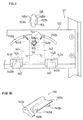
- Figs. 9 and 10 show a nipping device of a transfer unit according to the second embodiment.
- Nippers 140 are provided on the outer surface of the stay 132, and pivoting levers 141 and 142 are provided on the inner surface thereof.
- the same structure as shown in Fig. 9 is also provided in a stay on the opposite side.
- four nippers 140 are provided, and four pivoting levers corresponding to the nippers 140 are provided.
- Each nipper 140 has a relatively wide sheet retainer tab 140a in its central portion, and sheet lifting portions 140b are provided on either side of the sheet retainer tab 140a, as shown in Fig. 10.
- the sheet lifting portions 140b slope inward from the sheet retainer tab 140a.
- a mount portion 140c is formed to support these portions 140a and 140b, and the mount portion 140c is supported pivotally by means of a pin and related elements in a notch formed in the stay 132.
- a cylindrical engaging portion 140d projects downward from the lower surface of the support portion 140c. The engaging portion 140d penetrates the stay 132 and projects inside the transfer drum 121.
- the pivoting levers 141 and 142 are disposed symmetrically and each have an L-shaped form consisting of a long portion in line with the drum's rotating direction and a shorter portion at right angles thereto.
- Each of the levers 141 and 142 is rotatably supported on the stay 132 in the region of its bend by means of a pin 143.
- Opposed projecting portions 141b and 142b are formed in respective ends of long portions 141a and 142b of the levers.
- Respective ends of short portions 141c and 142c of the cams have a bifurcate form provided with central notches 141d and 142d, and the engaging portions 140d of the nippers 140 engage in the notches 141d and 142d.
- Pins 144 project upward near the projecting portions 141b and 142b of the pivoting levers 141 and 142, and these pins 144 are inserted in arced guide slots 132a and 132b in the stay 132.
- One end of a tension spring 145 is attached to each pin 144 on the outer surface of the stay 132, and the other end of the tension spring 145 is attached to the stay 132.
- pivoting levers 141 and 142 are pivotal on the corresponding axes (pins 143) which intersect the circumferential surface of the transfer drum 121, and are under the retentive agency of the tension springs 145 such that their projecting portions 141b approach each other.
- Drive cams 148 and 153 are provided on rotator shafts rotatably supported on a rotator sub frame inside the transfer drum 121.
- the drive cams 148 and 153 are disposed so as to be able to come into driving contact with the projecting portions 141b and 142b of the pivoting levers 141 and 142, respectively.
- Both lateral surfaces 148a and 148b of the cams 148 and those of the cams 153 are oval surfaces limiting the turning of the pivoting levers 141 and 142.
- the drive cams 148 provided corresponding to a sheet separating position have a greater width than the cams 153 provided corresponding to a sheet nipping position.
- the projecting portions 141b and 142b of the rotating cams 141 and 142 pass along the laterally bulging portions of the cam surfaces 153a and 153b of the cams 153, and gradually approach each other, since the projecting portions 141b and 142b are urged toward each other under the agency of the tension springs 145. Consequently, the pivoting levers 141 and 142 pivot in the directions opposite to those described above, and the engaging portions 140d of the nippers 140 are moved upward in Fig. 11. Then, the nippers 140 pivot in the direction pressing the printing sheet toward the inside of the transfer drum 121.
Landscapes
- Engineering & Computer Science (AREA)
- Mechanical Engineering (AREA)
- Electrostatic Charge, Transfer And Separation In Electrography (AREA)
Claims (19)
- Greifvorrichtung, die in einer Übertragungseinheit vorgesehen ist und einen feststehenden Bereich (47) und ein drehbares Element (21) als Übertragungstrommel, die von dem feststehenden Bereich drehbar abgestützt ist, aufweist, wobei die Greifeinrichtung die Funktion hat, ein Druckblatt auf der Umfangsfläche (39) des drehbaren Elements festzuhalten und das Druckblatt von dem drehbaren Element (21) zu trennen, wobei die Vorrichtung folgendes aufweist:
Greifeinrichtungen (40), die öffnungsfähig an der Umfangsfläche (39) des drehbaren Elements (21) angeordnet sind, um die Vorderkante des dort zugeführten Druckblatts festzuhalten;
eine Schwenkhebeleinrichtung, die in dem drehbaren Element (21) vorgesehen ist und Schwenkhebel (41, 42) aufweist, um die Greifeinrichtungen (40) zu öffnen und zu schließen;
dadurch gekennzeichnet,
daß die Schwenkhebel (41, 42) auf Achsen drehbar sind, die senkrecht zu einer Tangente zu der Umfangsfläche des drehbaren Elements (21) angeordnet sind, wobei diese Achsen die Umfangsfläche schneiden; und
daß eine Antriebseinrichtung (46, 48, 51, 52, 53) in dem feststehenden Bereich (47) angeordnet ist, um die Schwenkhebeleinrichtung zu betätigen. - Greifvorrichtung nach Anspruch 1, wobei das drehbare Element ein Paar von Kränzen (30, 31), die an jedem Ende der Übertragungseinheit angeordnet sind, und ein Verbindungselement (32) aufweist, das das Kranzpaar miteinander verbindet und einen Bereich der Umfangsfläche des drehbaren Elements (21) bildet; und
die Greifeinrichtungen (40) und die Schwenkhebeleinrichtung an dem Verbindungselement (32) angebracht sind. - Greifvorrichtung nach Anspruch 1 oder 2, wobei die Schwenkhebeleinrichtung federnde Elemente (45) aufweist, mittels welcher die Schwenkhebel (41, 42) die Greifeinrichtungen (40) schließen; und
die Antriebseinrichtung Antriebsnocken (48, 53) aufweist, die in treibenden Kontakt mit den Schwenkhebeln (41, 42) in der Richtung zum Öffnen der Greifeinrichtungen gelangen. - Greifvorrichtung nach Anspruch 2 oder 3, wobei
das Verbindungselement (32) einen bogenförmigen Schlitz (32a, 32b) hat,
wobei jeder der Schwenkhebel (41, 42) einen Zapfen (44) aufweist, von dem jeweils ein Ende in den Schlitz (32a, 32b) eingesetzt ist, und
wobei das federnde Element (45) eine Zugfeder ist, deren eines Ende an dem Zapfen (44) in Eingriff ist und deren anderes Ende an dem Verbindungselement (32) in Eingriff ist. - Greifvorrichtung nach einem der Ansprüche 1-4, wobei
jeder Schwenkhebel (41, 42) einen Sperrbereich (41a, 42a) hat,
jede der Greifeinrichtungen (40) aufweist: einen Eingriffsbereich (40d) zum Eingriff mit dem Sperrbereich (41a, 42a) der Schwenkhebel (41, 42), einen Festlegebereich (40a) zum Festlegen eines Druckblatts an der Umfangsfläche (39) des drehbaren Elements (21), und einen Hebebereich (40b) zum Heben des Druckblatts weg von der Umfangsfläche (39) des drehbaren Elements (21). - Greifvorrichtung nach einem der Ansprüche 3-5, wobei die Antriebseinrichtung aufweist: einen ersten Antriebsnocken (53), der angeordnet ist, um einer Blattgreifposition der Übertragungseinheit (21) zu entsprechen, und einen zweiten Antriebsnocken (48), der einen größeren Hub der Greifeinrichtungen als der erste Antriebsnocken (53) bewirkt und angeordnet ist, um einer Blatttrennposition der Übertragungseinheit zu entsprechen.
- Greifvorrichtung nach Anspruch 3, wobei
ein Ende jedes der Schwenkhebel (41, 42) von dem drehbaren Element (21) schwenkbar abgestützt ist und jedes entgegengesetzte Ende als ein Kontaktende (41b, 42b) zum Eingriff mit der Antriebseinrichtung (46, 48, 51, 52, 53) dient, um die Greifeinrichtungen (40) zu öffnen und zu schließen,
wobei die Schwenkhebel (41, 42) der Schwenkhebeleinrichtung in einander gegenüberstehenden Paaren wirksam sind, und
wobei die Nocken (48, 53) der Antriebseinrichtung angeordnet sind, um fähig zu sein, in treibenden Kontakt mit den Kontaktenden (41b, 42b) der Schwenkhebel (41, 42) zu gelangen, und um entlang der Richtung der Drehachse des drehbaren Elements (21) gleitbar zu sein. - Greifvorrichtung nach Anspruch 7, wobei die Antriebseinrichtung eine Drehwelle (46) aufweist, die die Antriebsnocken (48, 53) angrenzend an die Drehachse des drehbaren Elements (21) auf solche Weise haltert, daß diese Nocken (48, 53) gleitbar, aber nicht drehbar sind, und auf der Drehwelle (46) eine Einrichtung (55) vorgesehen ist, um einen Bewegungsbereich der Antriebsnocken (48, 53) zu begrenzen.
- Greifvorrichtung nach Anspruch 3, wobei die Antriebsnocken (48, 53) jeweils Nockenflächen (48a, 53a) haben, die das Öffnen und Schließen der Greifeinrichtungen (40) antreiben.
- Greifvorrichtung nach Anspruch 9, wobei die Nockenflächen (48a, 53a) der Antriebsnocken (48, 53) die Greifeinrichtungen (40) veranlassen, die seitlichen Enden des Druckblatts auf dem drehbaren Element (21) um einen Betrag zu heben, der kleiner als derjenige des Blattbereichs in der Mitte des drehbaren Elements ist.
- Greifvorrichtung nach Anspruch 3, die ferner aufweist: eine Positioniereinrichtung (49, 51) zum Bewegen der Antriebsnocken (48, 53) zwischen einer Betriebsposition, in der die Nocken (48, 53) mit den Schwenkhebeln (41, 42) in Kontakt gelangen, um sie zu drehen, und einer zurückgezogenen Position, in der die Antriebsnocken aus dem Bereich des Antriebskontakts mit den Schwenkhebeln (41, 42) zurückgezogen sind.
- Greifvorrichtung nach Anspruch 11, wobei die Antriebseinrichtung einen Antriebsnocken (53), der in einer Blattgreifposition der Übertragungseinheit (21) angeordnet ist, und einen Antriebsnocken (48), der in einer Blatttrennposition der Übertragungseinheit angeordnet ist, aufweist.
- Greifvorrichtung nach Anspruch 3, wobei ein Ende jedes Schwenkhebels (41, 42) schwenkbar von dem drehbaren Element (21) gehaltert ist und sein jeweiliges entgegengesetztes Ende (41b, 42b) als ein gegenwirkendes Kontaktende dient, wobei die Schwenkhebel (41, 42) der Schwenkhebeleinrichtung in einander gegenüberstehenden Paaren wirksam sind, und wobei die Antriebseinrichtung einen Antriebsnocken (48, 53) aufweist, der Nockenflächen (48a, 53a) hat, die in treibenden Kontakt mit den Kontaktenden (41b, 42b) der Schwenkhebel gelangen, so daß ein veränderliches Ausmaß an Heben an einem Druckblatt bewirkt wird.
- Greifvorrichtung nach Anspruch 13, wobei das Ausmaß des Hebens, das von den Flächen (48a, 53a) der Antriebseinrichtung näher an der Mitte des drehbaren Elements (21) bewirkt wird, größer als das Ausmaß des Hebens ist, das von den anderen dabei vorhandenen Nockenflächen bewirkt wird.
- Greifvorrichtung nach einem der Ansprüche 2-14, die ferner aufweist: ein an dem drehbaren Element (21) angebrachtes Grundmaterial (39), das die Umfangsfläche der Übertragungseinheit bildet, wobei das Grundmaterial (39) austauschbar ist, wobei
die Greifeinrichtung (40) einen Festlegebereich (40a) aufweist, um das Druckblatt an der Oberfläche des Grundmaterials (39) festzulegen, und
die Schwenkhebeleinrichtung fähig ist, die Greifeinrichtungen (40) abzustützen, wobei der Festlegebereich (40a) ausreichend weit nach außen von der Umfangsfläche (39) der Übertragungseinheit weg geöffnet wird. - Greifvorrichtung nach Anspruch 15, wobei
die Schwenkhebel (41, 42) Sperrbereiche (41a, 42a) haben und
die Greifeinrichtungen aufweisen: einen Eingriffsbereich (40d) zum Eingriff mit den Sperrbereichen (41a, 42a), einen Festlegebereich (40a), um das Druckblatt auf der Umfangsfläche des drehbaren Elements (21) festzulegen, und eine Hebebereich (40b), um ein Druckblatt von der Umfangsfläche des drehbaren Elements wegzuheben. - Greifvorrichtung nach Anspruch 15 oder 16, wobei die Schwenkhebeleinrichtung einen Bereich aufweist, auf dem der Eingriffsbereich (40d) der Greifeinrichtungen gleiten kann.
- Greifvorrichtung nach Anspruch 1 oder 2, wobei die Antriebseinrichtung Mittel (46, 48, 51, 52, 53) aufweist, um das Öffnen und Schließen der Greifeinrichtungen (40) durch die Schwenkhebeleinrichtung zu regeln.
- Greifvorrichtung nach Anspruch 18, wobei die Schwenkhebeleinrichtung federnde Elemente (45) aufweist, mittels welcher die Schwenkhebel (41, 42) die Greifeinrichtungen schließen, und
die Antriebseinrichtung Antriebsnocken (48, 53) aufweist, die in treibenden Kontakt mit den Schwenkhebeln (41, 42) in der Richtung zum Öffnen der Greifeinrichtungen (40) gelangen.
Applications Claiming Priority (6)
| Application Number | Priority Date | Filing Date | Title |
|---|---|---|---|
| JP2320040A JPH04194885A (ja) | 1990-11-22 | 1990-11-22 | 転写装置のクリップ装置 |
| JP2320038A JPH0830923B2 (ja) | 1990-11-22 | 1990-11-22 | 転写装置のクリップ装置 |
| JP320038/90 | 1990-11-22 | ||
| JP320040/90 | 1990-11-22 | ||
| JP3073882A JPH04283781A (ja) | 1991-03-12 | 1991-03-12 | 転写装置のクリップ装置 |
| JP73882/91 | 1991-03-12 |
Publications (2)
| Publication Number | Publication Date |
|---|---|
| EP0488085A1 EP0488085A1 (de) | 1992-06-03 |
| EP0488085B1 true EP0488085B1 (de) | 1995-04-12 |
Family
ID=27301339
Family Applications (1)
| Application Number | Title | Priority Date | Filing Date |
|---|---|---|---|
| EP91119979A Expired - Lifetime EP0488085B1 (de) | 1990-11-22 | 1991-11-22 | Greifereinrichtung von einer Übertragungseinheit |
Country Status (3)
| Country | Link |
|---|---|
| US (1) | US5195740A (de) |
| EP (1) | EP0488085B1 (de) |
| DE (1) | DE69108867T2 (de) |
Family Cites Families (10)
| Publication number | Priority date | Publication date | Assignee | Title |
|---|---|---|---|---|
| US2593148A (en) * | 1946-09-27 | 1952-04-15 | Hoe & Co R | Sheet registering mechanism for printing |
| US2797097A (en) * | 1955-03-23 | 1957-06-25 | Anton R Stobb | Gripper for flexible sheet conveyor |
| US3221652A (en) * | 1963-12-19 | 1965-12-07 | Mestre Luis | Impression cylinder combination for a press |
| CA950933A (en) * | 1970-05-28 | 1974-07-09 | Xerox Corporation | Sheet gripping apparatus |
| US3729187A (en) * | 1971-09-17 | 1973-04-24 | Singer Co | Sheet handling device |
| JPS6121169U (ja) * | 1984-07-12 | 1986-02-07 | 日本ビクター株式会社 | 排紙機構 |
| DE3508697A1 (de) * | 1985-03-12 | 1986-09-25 | M.A.N.- Roland Druckmaschinen AG, 6050 Offenbach | Vorrichtung zur steuerung von greifern in bogenrotationsdruckmaschinen |
| US4900008A (en) * | 1986-12-22 | 1990-02-13 | Polaroid Corporation | Sheet clamping arrangement for rotatable drums |
| EP0276185B1 (de) * | 1987-01-19 | 1994-05-18 | Canon Kabushiki Kaisha | Verschmutzungsschutz für Blattgreifer |
| US4824096A (en) * | 1987-07-17 | 1989-04-25 | Polaroid Corporation | Sheet clamp counterbalancing system for high speed sheet handling drums |
-
1991
- 1991-11-19 US US07/794,587 patent/US5195740A/en not_active Expired - Fee Related
- 1991-11-22 DE DE69108867T patent/DE69108867T2/de not_active Expired - Fee Related
- 1991-11-22 EP EP91119979A patent/EP0488085B1/de not_active Expired - Lifetime
Also Published As
| Publication number | Publication date |
|---|---|
| DE69108867D1 (de) | 1995-05-18 |
| EP0488085A1 (de) | 1992-06-03 |
| DE69108867T2 (de) | 1995-11-23 |
| US5195740A (en) | 1993-03-23 |
Similar Documents
| Publication | Publication Date | Title |
|---|---|---|
| US7257351B2 (en) | Detaching/attaching mechanism and image forming device | |
| DE19506828A1 (de) | Aufzeichnungsvorrichtung | |
| CA1052405A (en) | Sprocket drive and stripper arrangement for computer form feeder apparatus | |
| US4155545A (en) | Sheet feed apparatus for electrostatic copying machine or the like | |
| JP3121161B2 (ja) | シート排出装置 | |
| US5253013A (en) | Image recording apparatus having releasable fixing device | |
| EP0488085B1 (de) | Greifereinrichtung von einer Übertragungseinheit | |
| EP0383983B1 (de) | Bildaufzeichnungsgerät | |
| US5028156A (en) | Sheet holding mechanism | |
| US5220387A (en) | Transfer unit of an image forming apparatus | |
| US6332610B1 (en) | Sheet containing apparatus | |
| EP1830230A1 (de) | Kupplungsanordnung für einen Antrieb an einem Spalt | |
| US6058286A (en) | Transfer unit of electrophotographic printer | |
| JP7746026B2 (ja) | 画像形成装置 | |
| JPH05173431A (ja) | 転写装置のクリップ装置 | |
| JP2556382Y2 (ja) | 機体ロック機構 | |
| JPH05173432A (ja) | 転写装置のクリップ装置 | |
| JPH0830923B2 (ja) | 転写装置のクリップ装置 | |
| JPS58182682A (ja) | 複写機の感光ドラム及び転写部材の支持装置 | |
| JPH04280276A (ja) | 転写装置のクリップ装置 | |
| JPH11189338A (ja) | 給紙装置及び画像形成装置 | |
| JPH07108748B2 (ja) | 複写機 | |
| JP3526968B2 (ja) | 画像記録装置 | |
| JPH0114589B2 (de) | ||
| JP3674369B2 (ja) | 画像形成装置 |
Legal Events
| Date | Code | Title | Description |
|---|---|---|---|
| PUAI | Public reference made under article 153(3) epc to a published international application that has entered the european phase |
Free format text: ORIGINAL CODE: 0009012 |
|
| AK | Designated contracting states |
Kind code of ref document: A1 Designated state(s): DE FR GB IT |
|
| 17P | Request for examination filed |
Effective date: 19920730 |
|
| 17Q | First examination report despatched |
Effective date: 19930914 |
|
| GRAA | (expected) grant |
Free format text: ORIGINAL CODE: 0009210 |
|
| AK | Designated contracting states |
Kind code of ref document: B1 Designated state(s): DE FR GB IT |
|
| ET | Fr: translation filed | ||
| REF | Corresponds to: |
Ref document number: 69108867 Country of ref document: DE Date of ref document: 19950518 |
|
| ITF | It: translation for a ep patent filed | ||
| PGFP | Annual fee paid to national office [announced via postgrant information from national office to epo] |
Ref country code: GB Payment date: 19951102 Year of fee payment: 5 |
|
| PGFP | Annual fee paid to national office [announced via postgrant information from national office to epo] |
Ref country code: FR Payment date: 19951116 Year of fee payment: 5 |
|
| PGFP | Annual fee paid to national office [announced via postgrant information from national office to epo] |
Ref country code: DE Payment date: 19951228 Year of fee payment: 5 |
|
| PLBE | No opposition filed within time limit |
Free format text: ORIGINAL CODE: 0009261 |
|
| STAA | Information on the status of an ep patent application or granted ep patent |
Free format text: STATUS: NO OPPOSITION FILED WITHIN TIME LIMIT |
|
| 26N | No opposition filed | ||
| PG25 | Lapsed in a contracting state [announced via postgrant information from national office to epo] |
Ref country code: GB Effective date: 19961122 |
|
| GBPC | Gb: european patent ceased through non-payment of renewal fee |
Effective date: 19961122 |
|
| PG25 | Lapsed in a contracting state [announced via postgrant information from national office to epo] |
Ref country code: FR Effective date: 19970731 |
|
| PG25 | Lapsed in a contracting state [announced via postgrant information from national office to epo] |
Ref country code: DE Effective date: 19970801 |
|
| REG | Reference to a national code |
Ref country code: FR Ref legal event code: ST |
|
| PG25 | Lapsed in a contracting state [announced via postgrant information from national office to epo] |
Ref country code: IT Free format text: LAPSE BECAUSE OF NON-PAYMENT OF DUE FEES;WARNING: LAPSES OF ITALIAN PATENTS WITH EFFECTIVE DATE BEFORE 2007 MAY HAVE OCCURRED AT ANY TIME BEFORE 2007. THE CORRECT EFFECTIVE DATE MAY BE DIFFERENT FROM THE ONE RECORDED. Effective date: 20051122 |