EP0487676B1 - Blattzählmaschine - Google Patents
Blattzählmaschine Download PDFInfo
- Publication number
- EP0487676B1 EP0487676B1 EP91911123A EP91911123A EP0487676B1 EP 0487676 B1 EP0487676 B1 EP 0487676B1 EP 91911123 A EP91911123 A EP 91911123A EP 91911123 A EP91911123 A EP 91911123A EP 0487676 B1 EP0487676 B1 EP 0487676B1
- Authority
- EP
- European Patent Office
- Prior art keywords
- sheet
- transfer
- stack
- pin
- corner
- Prior art date
- Legal status (The legal status is an assumption and is not a legal conclusion. Google has not performed a legal analysis and makes no representation as to the accuracy of the status listed.)
- Expired - Lifetime
Links
Images

Classifications
-
- G—PHYSICS
- G06—COMPUTING OR CALCULATING; COUNTING
- G06M—COUNTING MECHANISMS; COUNTING OF OBJECTS NOT OTHERWISE PROVIDED FOR
- G06M9/00—Counting of objects in a stack thereof
- G06M9/02—Counting of objects in a stack thereof by using a rotating separator incorporating pneumatic suction nozzles
Definitions
- This invention relates to a sheet counting apparatus for counting sheets in a stack of sheets.
- All of these machines utilise a generally flat hollow blade having a vacuum port and which is mounted in a cantilever fashion to pivot about an axis parallel to one edge of the blade, there being a pin orbiting in an elliptical or other complex path about the blade, so that when the blade is engaged in a stack of sheets and is pivoted between generally horizontal and downwardly inclined positions in synchronism with the orbiting pin, the corner of the sheet for the time being held by applied vacuum in contact with one side of the blade is separated from the stack and is then transferred by the pin to the other side of the blade.
- a counting device is triggered each time the mechanism transfers a sheet from one side of the blade to the other.
- This invention provides a sheet counting apparatus for counting sheets in a stack thereof, comprising transfer means arranged to act on a corner of the stack to separate the sheet corners from the stack on one side of the transfer means and to transfer the separated corners one at a time to the other side of the transfer means, and means to count the sheet corners as they are transferred, said transfer means comprising an elongate member having, in cross-section, a curved surface in which is formed a vacuum port and which member is arranged to engage in the stack whereby suction applied to the vacuum port may draw on to the curved surface an adjacent sheet corner, a transfer pin extending substantially parallel to said elongate member, means to move the pin in an orbit around the elongate member to transfer a sheet corner drawn on to the curved surface to the other side of the elongate member, and control means to control the supply of suction to the vacuum port to terminate the suction prior to the transfer of the corner by the orbiting pin from one side of the elongate member to the other side thereof and to re-establish the
- an elongate static member is engaged in the corner region of a stack of sheets.
- the apparatus is thus simplified in that no mechanism need be provided to drive the member, and as the transfer pin moves continuously in an orbit, the counting rate may be increased as there are no reciprocating parts.
- the curved surface of the elongate member minimises the angle through which a sheet corner is deformed during the counting process.
- the static element comprises a generally cylindrical hollow bar having an outer cylindrical surface and also defining said curved surface, the outer cylindrical surface having a smaller radius of curvature than said curved surface, and the vacuum port in the curved surface communicating with the interior of the bar, whereby suction may be applied to the port through the interior of the bar.
- the curved surface should blend smoothly with the outer cylindrical surface of the bar.
- control means comprises a valve member mounted for rotation within the bar and which valve member has a port which comes into and out of register with the vacuum port in the curved surface of the bar, means being provided to rotate the valve member in synchronism with the orbiting motion of the pin whereby suction is periodically applied to the vacuum port in a timed relationship to the pin motion.
- the valve member may take the form of a rotatable hollow spindle extending essentially co-axially within the static member, arranged for rotation synchronously with the pin.
- the vacuum port By applying the suction continuously to the spindle, the vacuum port will then receive the suction at the appropriate times to draw down the next sheet to be counted, so opening a gap in the stack for the pin, and then releasing that sheet as the transfer of that sheet to the other side of the member commences.
- Means may be provided for holding apart the sheet corners of the stack to both sides of the transfer means, and for gradually releasing the sheets to the transfer means.
- Such holding means may in effect open a gap in the corner region of the stack to receive the transfer means, and release sheets to the transfer means for counting thereby, as the counting proceeds.
- the means for counting sheets transferred by the transfer means may take any of a number of forms.
- combinations of such counting means may be employed to increase the reliability and accuracy of the count.
- This invention extends to sheet counting apparatus as defined above in combination with a table for supporting a stack of sheets, and means relatively to move the table and transfer means along the length of the stack as the counting progresses.
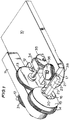
- the principal parts of the embodiment of sheet counting apparatus constructed in accordance with the present invention and arranged to act on a corner of a stack of sheets include a base plate 10 supporting a bracket 11 in which is journalled a drive shaft 12. Locked to shaft 12 is gear 13 meshing with teeth 14 formed in an outer ring 15 of the sheet transfer mechanism.
- the ring 15 is rotatably mounted on a static boss 16 secured to the bracket 11 and carries a transfer pin 17 arranged to extend parallel to the rotational axis of the ring 15.
- the transfer pin 17 is mounted for rotation in a low friction bearing 18.
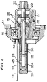
- Boss 16 has a hollow arm 20 which extends parallel to the rotational axis of ring 15, and has an elongate outer sleeve 21 secured thereto, which sleeve has a generally circular cross-sectional external shape, but includes a surface 22 of an increased radius of curvature blending smoothly with the cylindrical surface.
- a vacuum port 23 is formed in the surface 22.
- a spindle 25 carried on bearings 26 provided within a counter-bore in the boss 16, the spindle having a bore extending from the spindle end remote from the bearings 26.
- a valve member 25A rotatably disposed within the sleeve 21, the valve member having a valve port 45 which comes into and out of register with the vacuum port 23 on rotation of the spindle.
- a cross-drilling 27 in the spindle 25 connects the spindle bore to a chamber 28 formed in the boss 16, to which chamber is connected a suction (vacuum) source.
- a seal member 29 is provided in the counter-bore to effect a seal around spindle 25 adjacent its free end, and a pinion 30 is secured to the end of the spindle 25 beyond the seal member 29.
- bracket 11 Rotatably mounted on bracket 11 is an idler gear 31 which meshes with pinion 30 provided on the spindle 25 and with a similar pinion (not shown) mounted on the drive shaft 12.
- the gear trains are arranged so that on rotation of the drive shaft 12 by a motor (not shown), the transfer pin 17 orbits around the sleeve 21 in a circular path at the same rate as spindle 25 is turned within arm 20, but in the opposite sense, so turning the valve member 25A to bring the connected vacuum source into and out of communication with the vacuum port 23.
- the base plate 10 supports a mounting block 34 through which the drive shaft 12 extends and carries at its free end a helical gear 35 meshed with a similar helical gear 36 secured to shaft 37 extending through the base plate 10.
- a conical support drum 38 is secured to shaft 37 beneath the base plate 10, and has a helical groove 39 formed in its conical surface, as shown in Figure 4.
- a support finger 40 ( Figure 4) is attached to the block 34, to extend forwardly towards sleeve 21.
- the sheet counting apparatus using the transfer mechanism described above is completed by a table 41 ( Figure 3A) to support a stack of sheets to be counted, the table having suitable guides to locate the stack and a clamping arrangement therefor.
- the table is relatively movable with respect to the transfer mechanism in the direction normal to the plane of the base plate 10.
- a counting mechanism (not shown) is also provided, which increments a counter each time a sheet is transferred by the transfer mechanism.
- Such a counting mechanism may operate by monitoring the vacuum applied to the spindle 25, the count being incremented for each rotation of the outer ring 15 so long as a depression below some predetermined datum is present.
- an optical counting arrangement may be provided, to sense the transfer of a sheet by pin 17.
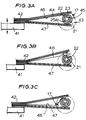
- FIG. 3A to 3D there is illustrated the sequence of operation of the transfer mechanism described above.
- a stack 42 of sheets is supported on the table 41 such that the corners of the sheets to be counted are inclined upwardly relative to the transfer mechanism 43, as illustrated at 44.
- the valve port 45 in valve member 25A is in register with the vacuum port 23 in the sleeve 21 and the corner of the sheet 46 next to be counted has been drawn on to the curved surface 22 by the reduced air pressure.
- the transfer pin 17 is moving in its circular orbit to enter the gap thus formed between the lowermost uncounted sheet 46 and the corners of the next sheets in the stack.
- a counter may be arranged to be incremented for each full turn of the pin 17, provided that there is no detected increase in the pressure within the spindle 25, which will occur when the last sheet of a stack has been counted and the valve port 45 in the valve member next registers with the vacuum port 23.
- Figure 4 illustrates a modification of the above described counting sequence, using a support finger 40 in conjunction with rotatable conical support drum 38, mentioned above.
- the support drum 38 and support finger 40 are arranged to reduce the loading on the transfer mechanism, and also to minimise the likelihood of damage occurring to the corners of sheets as they are transferred from one side to the other of the sleeve 21.
- the table 41 supporting the stack of sheets is moved relative to the sleeve 21, and so also relative to the support finger 40 which projects by a short distance into the stack of sheets to be counted, above the sleeve 21.
- Such movement of the table (and stack) relative to the support finger 40 allows sheets to transfer from one side of the finger to the other, so that the number of sheets resting on the arm 20 and awaiting counting is relatively small.
Landscapes
- Physics & Mathematics (AREA)
- General Physics & Mathematics (AREA)
- Engineering & Computer Science (AREA)
- Theoretical Computer Science (AREA)
- Sheets, Magazines, And Separation Thereof (AREA)
- Controlling Sheets Or Webs (AREA)
- Controlling Rewinding, Feeding, Winding, Or Abnormalities Of Webs (AREA)
- Plural Heterocyclic Compounds (AREA)
- Photovoltaic Devices (AREA)
- Spinning Or Twisting Of Yarns (AREA)
- Photosensitive Polymer And Photoresist Processing (AREA)
- Supplying Of Containers To The Packaging Station (AREA)
Claims (12)
- Bogenzählvorrichtung zum Zählen von Bögen eines Stapels von Bögen, mit einer Transportiereinrichtung (Figur 2), die dazu ausgestaltet ist, auf eine Ecke des Stapels zu wirken, um auf einer Seite der Transportiereinrichtung die Bogenecken vom Stapel abzulösen und um die abgelösten Ecken jeweils nacheinander auf die andere Seite der Transportiereinrichtung zu transportieren, und mit Einrichtungen, um die Bogenecken zu zählen, wenn diese transportiert werden, wobei die Transportiereinrichtung ein längliches Bauteil (21) enthält, das im Querschnitt eine gekrümmte Fläche (22) aufweist, in welcher eine Vakuumöffnung (23) ausgebildet ist, und wobei das Bauteil (21) dazu ausgestaltet ist, in den Stapel einzugreifen, wodurch der in der Vakuumöffnung (23) wirkende Unterdruck eine benachbarte Bogenecke gegen die gekrümmte Fläche (22) ansaugen kann, mit einem Transportierstift (17), der sich im wesentlichen parallel zum länglichen Bauteil (21) erstreckt, mit Einrichtungen (14, 15), um den Stift (17) auf einer Kreisbahn um das längliche Bauteil (21) zu bewegen, um eine gegen die gekrümmte Fläche (22) angesaugte Bogenecke auf die andere Seite des länglichen Bauteils (21) zu transportieren, und mit einer Steuereinrichtung (25, 45), um die Unterdruckzufuhr zur Vakuumöffnung (23) zu steuern, um den Unterdruck zu unterbrechen, bevor die Ecke durch den umlaufenden Stift (17) von einer Seite des länglichen Bauteils (21) auf dessen andere Seite transportiert wird, und um den Unterdruck erneut aufzubauen, um die Ecke des nachfolgenden Bogens im Stapel für den nächsten Transport gegen die gekrümmte Fläche (22) anzusaugen, dadurch gekennzeichnet, daß das längliche Bauteil (21) feststehend verbleibt, während es vom Stift (17) umkreist wird.
- Bogenzählvorrichtung nach Anspruch 1, dadurch gekennzeichnet, daß das längliche Bauteil (21) einen im wesentlichen zylindrischen Hohlstab aufweist, der eine äußere zylindrische Fläche hat und außerdem die gekrümmte Fläche (22) enthält, wobei die äußere zylindrische Fläche einen kleineren Krümmungsradius hat als die gekrümmte Fläche, und wobei die Vakuumöffnung (23) in der gekrümmten Fläche (22) mit dem Inneren des Stabes in Verbindung steht, wobei der Unterdruck über das Innere des Stabes in die Öffnung geleitet wird.
- Bogenzählvorrichtung nach Anspruch 2, dadurch gekennzeichnet, daß die Steuereinrichtung ein Ventilbauteil (25A) aufweist, das drehbar im Hohlstab (21) angeordnet ist, wobei das Ventilbauteil (25A) eine Öffnung (45) enthält, die mit der Vakuumöffnung (23) in der gekrümmten Fläche (22) des Stabes zusammen- und auseinanderfällt, wobei Einrichtungen (30, 25) vorgesehen sind, um das Ventilbauteil (25A) im Gleichlauf mit der kreisenden Bewegung des Stiftes (17) zu drehen, wobei der Unterdruck in zeitlicher Beziehung zur Stiftbewegung periodisch in die Vakuumöffnung (23) eingeleitet wird.
- Bogenzählvorrichtung nach einem der vorhergehenden Ansprüche, dadurch gekennzeichnet, daß das längliche Bauteil (21) und der Transportierstift (17) einseitig an einem Mechanismus (15, 16) angebracht sind, um das längliche Bauteil (21) nicht-drehbar zu halten, um den Stift (17) auf der Kreisbahn um das Bauteil (21) herumzubewegen und um den Unterdruck in die Vakuumöffnung (23) einzuleiten.
- Bogenzählvorrichtung nach einem der vorhergehenden Ansprüche, dadurch gekennzeichnet, daß Einrichtungen (38, 40) vorgesehen sind, um die Bogenecken des Stapels von beiden Seiten der Transportiereinrichtung beabstandet zu halten und um die Bögen schrittweise zur Transportiereinrichtung freizugeben.
- Bogenzählvorrichtung nach Anspruch 5, dadurch gekennzeichnet, daß die Einrichtungen, um die Ecken des Stapels von beiden Seiten der Transportiereinrichtung beabstandet zu halten, eine erste Einrichtung (40), um mit den ungezählten Bögen des Stapels einzugreifen und um die Bögen zur Transportiereinrichtung freizugeben, und eine zweite Einrichtung (38) aufweisen, die auf der anderen Seite der Transportiereinrichtung angeordnet ist, um auf der anderen Seite der Transportiereinrichtung die gezählten Bögen zu dem Stapel zusammenzufügen.
- Bogenzählvorrichtung nach Anspruch 6, dadurch gekennzeichnet, daß die erste Einrichtung eine Platte (40) oder eine Rolle aufweist, die in die Ecke des Stapels eingreift und ausgestaltet ist, um die Bögen schrittweise zur Transportiereinrichtung freizugeben.
- Bogenzählvorrichtung nach Anspruch 6 oder nach Anspruch 7, dadurch gekennzeichnet, daß die zweite Einrichtung ein drehbares Bauteil (38) mit einem schraubenförmigen Einschnitt (39) aufweist, in welchen die Ecke eines Bogens, der durch die Transportiereinrichtung transportiert wurde, eingreift, um den transportierten Bogen auf der von der Transportiereinrichtung abgewandten Seite des drehbaren Bauteils (38) neu zu stapeln.
- Bogenzählvorrichtung nach Anspruch 8, dadurch gekennzeichnet, daß das drehbare Bauteil (38) eine konische Außenfläche aufweist, in welcher der schraubenförmige Einschnitt (39) ausgebildet ist, wobei die neu gestapelten Bögen an dessen konischer Fläche anliegen.
- Bogenzählvorrichtung nach einem der vorhergehenden Ansprüche, dadurch gekennzeichnet, daß die Einrichtungen zum Zählen der durch die Transportiereinrichtung transportierten Bögen zumindest eine optische Einrichtung enthalten, um zu erfassen, wann eine Bogenecke durch die Transportiereinrichtung transportiert wurde, bzw. einen Zähler für vollständige Umläufe des Transportierstiftes aufweisen, in Verbindung mit Einrichtungen, die für den plötzlichen Druck in der Vakuumöffnung ursächlich sind, um zu erfassen, ob Unterdruck in die Öffnung eingeleitet wurde, ohne daß eine Bogenecke auf die gekrümmte Oberfläche angesaugt wurde.
- Bogenzählvorrichtung nach einem der vorhergehenden Ansprüche, dadurch gekennzeichnet, daß durch die Einrichtungen (14, 15) zum Bewegen des Transportierstiftes (17) bewirkt wird, daß sich der Stift (17) auf einer elliptischen oder kreisförmigen Bahn bewegt.
- Bogenzählvorrichtung nach einem der vorhergehenden Ansprüche, in Verbindung mit einem Tisch (41) zum Halten eines Stapels (42) von Bögen und mit Einrichtungen, um den Tisch und die Transportiereinrichtung während des Zählvorganges relativ zueinander entlang der Länge des Stapels zu bewegen.
Applications Claiming Priority (3)
| Application Number | Priority Date | Filing Date | Title |
|---|---|---|---|
| GB9013335 | 1990-06-14 | ||
| GB909013335A GB9013335D0 (en) | 1990-06-14 | 1990-06-14 | Pin and roller counter |
| PCT/GB1991/000951 WO1991020059A1 (en) | 1990-06-14 | 1991-06-13 | Sheet counting apparatus |
Publications (2)
| Publication Number | Publication Date |
|---|---|
| EP0487676A1 EP0487676A1 (de) | 1992-06-03 |
| EP0487676B1 true EP0487676B1 (de) | 1995-05-10 |
Family
ID=10677644
Family Applications (1)
| Application Number | Title | Priority Date | Filing Date |
|---|---|---|---|
| EP91911123A Expired - Lifetime EP0487676B1 (de) | 1990-06-14 | 1991-06-13 | Blattzählmaschine |
Country Status (8)
| Country | Link |
|---|---|
| US (1) | US5262620A (de) |
| EP (1) | EP0487676B1 (de) |
| JP (1) | JPH05503184A (de) |
| AT (1) | ATE122486T1 (de) |
| DE (1) | DE69109630T2 (de) |
| ES (1) | ES2073760T3 (de) |
| GB (1) | GB9013335D0 (de) |
| WO (1) | WO1991020059A1 (de) |
Families Citing this family (1)
| Publication number | Priority date | Publication date | Assignee | Title |
|---|---|---|---|---|
| SE515016C2 (sv) * | 1995-08-15 | 2001-05-28 | Jan Lundberg | Arkräknare |
Family Cites Families (7)
| Publication number | Priority date | Publication date | Assignee | Title |
|---|---|---|---|---|
| GB784209A (en) * | 1955-04-23 | 1957-10-02 | Axel Edvin Rosswall | Improvements in or relating to a machine for separating sheets arranged in a pile for the purpose of counting th em |
| GB896410A (en) * | 1957-05-09 | 1962-05-16 | George Edmond Brackenbury Abel | Improvements in or relating to apparatus for acting in turn on sheets |
| GB1037319A (en) * | 1964-07-02 | 1966-07-27 | Vacuumatic Ltd | Improvements in or relating to sheet separating apparatus |
| JPS534301B2 (de) * | 1971-11-30 | 1978-02-16 | ||
| JPS532344B2 (de) * | 1972-02-22 | 1978-01-27 | ||
| GB1455108A (en) * | 1972-11-24 | 1976-11-10 | Vacuumatic Ltd | Apparatus for counting a stack of sheets |
| US3962564A (en) * | 1974-09-19 | 1976-06-08 | Vacuumatic Limited | Apparatus for counting a stack of sheets |
-
1990
- 1990-06-14 GB GB909013335A patent/GB9013335D0/en active Pending
-
1991
- 1991-06-13 AT AT91911123T patent/ATE122486T1/de active
- 1991-06-13 DE DE69109630T patent/DE69109630T2/de not_active Expired - Fee Related
- 1991-06-13 EP EP91911123A patent/EP0487676B1/de not_active Expired - Lifetime
- 1991-06-13 US US07/834,236 patent/US5262620A/en not_active Expired - Fee Related
- 1991-06-13 ES ES91911123T patent/ES2073760T3/es not_active Expired - Lifetime
- 1991-06-13 WO PCT/GB1991/000951 patent/WO1991020059A1/en not_active Ceased
- 1991-06-13 JP JP3510566A patent/JPH05503184A/ja active Pending
Also Published As
| Publication number | Publication date |
|---|---|
| GB9013335D0 (en) | 1990-08-08 |
| DE69109630T2 (de) | 1996-01-11 |
| ATE122486T1 (de) | 1995-05-15 |
| JPH05503184A (ja) | 1993-05-27 |
| WO1991020059A1 (en) | 1991-12-26 |
| EP0487676A1 (de) | 1992-06-03 |
| ES2073760T3 (es) | 1995-08-16 |
| US5262620A (en) | 1993-11-16 |
| DE69109630D1 (de) | 1995-06-14 |
Similar Documents
| Publication | Publication Date | Title |
|---|---|---|
| KR930010160B1 (ko) | 지엽류의 반송방출회수기구 | |
| JPS62249833A (ja) | カセツトにx線シ−トフイルムを装填する装置 | |
| US3127027A (en) | Cam for carton handling machine | |
| JPH05246617A (ja) | バックルフォールディングマシン | |
| US5262620A (en) | Sheet counting apparatus | |
| US4282439A (en) | X-ray photographing machine using sheet films | |
| US5630312A (en) | Ejection mechanism for envelope inserting machine | |
| US4940219A (en) | Apparatus for forming a stack of flat objects such as letters | |
| US3795796A (en) | Stop-motion for sheet counters | |
| JPH04313560A (ja) | 輪転印刷機の折り機に設けられた減速装置 | |
| US5657982A (en) | Mail sorting device | |
| US4930763A (en) | Paper feeding apparatus | |
| US3659838A (en) | Material handling device | |
| CA1215401A (en) | Stacker for flat objects | |
| JPH11157675A (ja) | シート送り装置 | |
| CA2368032C (en) | On-edge stacker | |
| JPS6334514B2 (de) | ||
| US3838255A (en) | Apparatus for counting a stack of sheets | |
| JPS586838Y2 (ja) | 紙葉類集積装置 | |
| JP3865804B2 (ja) | シート体搬送装置の連結構造 | |
| JPS586652B2 (ja) | ナンケンナドノ トリダシソウチ | |
| JPS58103083A (ja) | 紙葉類計数機 | |
| US4123049A (en) | Printing plate transfer apparatus | |
| US5709378A (en) | Mechanism for counting stacked sheets | |
| US3284079A (en) | Device for feeding paper sheets in printing machines |
Legal Events
| Date | Code | Title | Description |
|---|---|---|---|
| PUAI | Public reference made under article 153(3) epc to a published international application that has entered the european phase |
Free format text: ORIGINAL CODE: 0009012 |
|
| AK | Designated contracting states |
Kind code of ref document: A1 Designated state(s): AT BE CH DE DK ES FR GB GR IT LI LU NL SE |
|
| 17P | Request for examination filed |
Effective date: 19920619 |
|
| 17Q | First examination report despatched |
Effective date: 19931015 |
|
| GRAA | (expected) grant |
Free format text: ORIGINAL CODE: 0009210 |
|
| AK | Designated contracting states |
Kind code of ref document: B1 Designated state(s): AT BE CH DE DK ES FR GB GR IT LI LU NL SE |
|
| PG25 | Lapsed in a contracting state [announced via postgrant information from national office to epo] |
Ref country code: CH Effective date: 19950510 Ref country code: BE Effective date: 19950510 Ref country code: AT Effective date: 19950510 Ref country code: LI Effective date: 19950510 Ref country code: GR Free format text: LAPSE BECAUSE OF FAILURE TO SUBMIT A TRANSLATION OF THE DESCRIPTION OR TO PAY THE FEE WITHIN THE PRESCRIBED TIME-LIMIT Effective date: 19950510 Ref country code: DK Effective date: 19950510 |
|
| REF | Corresponds to: |
Ref document number: 122486 Country of ref document: AT Date of ref document: 19950515 Kind code of ref document: T |
|
| PGFP | Annual fee paid to national office [announced via postgrant information from national office to epo] |
Ref country code: GB Payment date: 19950612 Year of fee payment: 5 |
|
| REF | Corresponds to: |
Ref document number: 69109630 Country of ref document: DE Date of ref document: 19950614 |
|
| PGFP | Annual fee paid to national office [announced via postgrant information from national office to epo] |
Ref country code: ES Payment date: 19950616 Year of fee payment: 5 |
|
| PGFP | Annual fee paid to national office [announced via postgrant information from national office to epo] |
Ref country code: NL Payment date: 19950628 Year of fee payment: 5 |
|
| PGFP | Annual fee paid to national office [announced via postgrant information from national office to epo] |
Ref country code: FR Payment date: 19950629 Year of fee payment: 5 |
|
| ITF | It: translation for a ep patent filed | ||
| PG25 | Lapsed in a contracting state [announced via postgrant information from national office to epo] |
Ref country code: LU Free format text: LAPSE BECAUSE OF NON-PAYMENT OF DUE FEES Effective date: 19950630 |
|
| ET | Fr: translation filed | ||
| PG25 | Lapsed in a contracting state [announced via postgrant information from national office to epo] |
Ref country code: SE Effective date: 19950810 |
|
| REG | Reference to a national code |
Ref country code: CH Ref legal event code: PL |
|
| REG | Reference to a national code |
Ref country code: ES Ref legal event code: FG2A Ref document number: 2073760 Country of ref document: ES Kind code of ref document: T3 |
|
| PGFP | Annual fee paid to national office [announced via postgrant information from national office to epo] |
Ref country code: DE Payment date: 19950817 Year of fee payment: 5 |
|
| PLBE | No opposition filed within time limit |
Free format text: ORIGINAL CODE: 0009261 |
|
| STAA | Information on the status of an ep patent application or granted ep patent |
Free format text: STATUS: NO OPPOSITION FILED WITHIN TIME LIMIT |
|
| 26N | No opposition filed | ||
| PG25 | Lapsed in a contracting state [announced via postgrant information from national office to epo] |
Ref country code: GB Effective date: 19960613 |
|
| PG25 | Lapsed in a contracting state [announced via postgrant information from national office to epo] |
Ref country code: ES Free format text: LAPSE BECAUSE OF THE APPLICANT RENOUNCES Effective date: 19960614 |
|
| PG25 | Lapsed in a contracting state [announced via postgrant information from national office to epo] |
Ref country code: NL Effective date: 19970101 |
|
| GBPC | Gb: european patent ceased through non-payment of renewal fee |
Effective date: 19960613 |
|
| PG25 | Lapsed in a contracting state [announced via postgrant information from national office to epo] |
Ref country code: FR Effective date: 19970228 |
|
| PG25 | Lapsed in a contracting state [announced via postgrant information from national office to epo] |
Ref country code: DE Effective date: 19970301 |
|
| NLV4 | Nl: lapsed or anulled due to non-payment of the annual fee |
Effective date: 19970101 |
|
| REG | Reference to a national code |
Ref country code: FR Ref legal event code: ST |
|
| REG | Reference to a national code |
Ref country code: ES Ref legal event code: FD2A Effective date: 19991007 |
|
| PG25 | Lapsed in a contracting state [announced via postgrant information from national office to epo] |
Ref country code: IT Free format text: LAPSE BECAUSE OF NON-PAYMENT OF DUE FEES;WARNING: LAPSES OF ITALIAN PATENTS WITH EFFECTIVE DATE BEFORE 2007 MAY HAVE OCCURRED AT ANY TIME BEFORE 2007. THE CORRECT EFFECTIVE DATE MAY BE DIFFERENT FROM THE ONE RECORDED. Effective date: 20050613 |