EP0487145B1 - Blockiervorrichtung für Last mit Rädern, insbesondere für Hebebühne - Google Patents
Blockiervorrichtung für Last mit Rädern, insbesondere für Hebebühne Download PDFInfo
- Publication number
- EP0487145B1 EP0487145B1 EP91202967A EP91202967A EP0487145B1 EP 0487145 B1 EP0487145 B1 EP 0487145B1 EP 91202967 A EP91202967 A EP 91202967A EP 91202967 A EP91202967 A EP 91202967A EP 0487145 B1 EP0487145 B1 EP 0487145B1
- Authority
- EP
- European Patent Office
- Prior art keywords
- section bar
- seat
- bar portion
- rotatable
- latch
- Prior art date
- Legal status (The legal status is an assumption and is not a legal conclusion. Google has not performed a legal analysis and makes no representation as to the accuracy of the status listed.)
- Expired - Lifetime
Links
- 230000000903 blocking effect Effects 0.000 title claims description 9
- 230000000717 retained effect Effects 0.000 description 2
Images

Classifications
-
- B—PERFORMING OPERATIONS; TRANSPORTING
- B60—VEHICLES IN GENERAL
- B60P—VEHICLES ADAPTED FOR LOAD TRANSPORTATION OR TO TRANSPORT, TO CARRY, OR TO COMPRISE SPECIAL LOADS OR OBJECTS
- B60P1/00—Vehicles predominantly for transporting loads and modified to facilitate loading, consolidating the load, or unloading
- B60P1/44—Vehicles predominantly for transporting loads and modified to facilitate loading, consolidating the load, or unloading having a loading platform thereon raising the load to the level of the load-transporting element
- B60P1/4457—Means for immobilising the load or preventing it from rolling off during lifting; Man-rails
-
- B—PERFORMING OPERATIONS; TRANSPORTING
- B60—VEHICLES IN GENERAL
- B60P—VEHICLES ADAPTED FOR LOAD TRANSPORTATION OR TO TRANSPORT, TO CARRY, OR TO COMPRISE SPECIAL LOADS OR OBJECTS
- B60P3/00—Vehicles adapted to transport, to carry or to comprise special loads or objects
- B60P3/06—Vehicles adapted to transport, to carry or to comprise special loads or objects for carrying vehicles
- B60P3/07—Vehicles adapted to transport, to carry or to comprise special loads or objects for carrying vehicles for carrying road vehicles
- B60P3/073—Vehicle retainers
- B60P3/075—Vehicle retainers for wheels, hubs, or axle shafts
-
- B—PERFORMING OPERATIONS; TRANSPORTING
- B66—HOISTING; LIFTING; HAULING
- B66F—HOISTING, LIFTING, HAULING OR PUSHING, NOT OTHERWISE PROVIDED FOR, e.g. DEVICES WHICH APPLY A LIFTING OR PUSHING FORCE DIRECTLY TO THE SURFACE OF A LOAD
- B66F7/00—Lifting frames, e.g. for lifting vehicles; Platform lifts
- B66F7/28—Constructional details, e.g. end stops, pivoting supporting members, sliding runners adjustable to load dimensions
Definitions
- This invention relates to a device for blocking wheel-mounted loads, in particular for lifting platforms.
- Lifting platforms are currently provided with rotatable plates oer flanges, which besides being intrinsically dangerous because of their blade configuration considerably complicate the loading operation by requiring a wheel-mounted load to be securely held while simultaneously tilting it, and with the further complication that this operation is generally carried out with the lifting platform inclined so that it touches the ground.
- a blocking device for wheel-mounted loads, in particular for lifting platforms is already known, which device presents the features indicated in the preamble of claim 1.
- the rotatable section bar portion is linked to a rotatable shackle which determines the raised position of the rotatable section bar portion holding it in this position.
- the object of the present invention is to improve and simplify the said known art by providing a blocking device for wheel-mounted loads which enables both the loads and the blocking device to be easily manoeuvred.
- the section bar portions have an essentially C-shaped hollow cross-section defining on one side a first seat for housing and guiding said means for selecting the locked or released state and on the other side a second seat for housing said elastic means and hinge means to enable the rotatable section bar portion to be rotated.
- the elastic means preferably consist of a torsion spring arranged to constantly urge the rotatably movable section bar portion out of the seat provided in the lifting platform.
- the means for selecting the locked or released state of the rotatable secton bar portion consist of a latch fixed to a rod slidable within a guide element, between the latch and guide elements there being provided a sleeve for locking/releasing the travel of said rod and a spring coaxial to this latter; the sleeve, the spring, the rod and its guide element being housed in one of the fixed lateral section bar portions, the latch being able to engage the rotatably movable central portion.
- the sleeve is provided with a two-position selector projecting from the loading surface and able to lock the latch within the fixed lateral section bar portion, or enable it to engage said rotatably movable central section bar portion.
- the section bar surface comprises a portion with a radius of curvature equal to the distance between the centre of rotation and the surface itself.
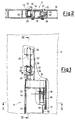
- the reference numeral 11 indicates overall a device for blocking wheel-mounted loads on a lifting platform 12.
- a seat 13 housing the device of the invention is provided in the lifting platform.
- the device 11 is composed essentially of a central section bar portion 14, occupying most of the width of the lifting platform 12.
- the section bar portions 14 and 15 have an essentially C-shaped hollow cross-section defining on one side a first seat 16 of substantially square profile and on the other side a second seat 17 of substantially circular profile housing pins 18 which enable the central section bar portion 14 to rotate relative to the lateral portions 15.
- the central section bar portion 14 is constantly urged out of the seat 13 by a spring 19 which in a preferred embodiment of the present invention is a torsion spring engaged with the seat 13 and with the inner surface of said central section bar portion 14.
- the mechanism 20 consists of a latch 21 fixed to a rod 22 slidable within a sleeve 23 and a guide element 24. Between the sleeve 23 and guide element 24 there is a spring 25 which acts at one end against the guide element 24 and at the other end against a ring 26.
- the ring 26 is rigid with the rod 22 and is in contact with the sleeve 23 only when in the position shown in Figure 5, whereas when in the position shown in Figure 4 it does not force against the sleeve 23 although it may come into contact with it.
- Above the sleeve 23 there is provided in the surface of the lifting platform 12 a slot 27 defining a housing with two engagement positions 28 and 29 for a selector 30 connected to the rod 22.
- At least the central section bar portion 14 comprises on that side of its rear surface close to the pins 18 a first abutment tooth 31 which acts against an edge portion 32 of the seat 13.
- That outer surface 33 of the central section bar portion 14 defining a wall of the seat 16 of square cross-section has for example a curvature with a radius equal to the distance between it and the centre of rotation defined in practice by the geometrical centre of the pin 18.
- the rod 22, which holds the latch 21, is constantly urged towards the central section bar portion 14 by the spring 25, so that if the selector 30 is in the position indicated by 28 (shown in Figure 1), the latch 21, which has its bevelled face pointing upwards, allows the central section bar portion 14 to descend into the seat 13 and remain locked therein once engaged by it.
- the selector 30, which projects only slightly from the lifting platform, can be operated by simply pressing for example with one foot, to lock or release the rotational movement of the central section bar portion 14.
- Such lifting platforms are generally required to lie inclined to the ground (the road surface) to allow said wheel-mounted loads to be positioned on them. These loads therefore have to be retained on the platform under total safety conditions, with no possibility of their moving either forwards or backwards.
Landscapes
- Engineering & Computer Science (AREA)
- Mechanical Engineering (AREA)
- Transportation (AREA)
- Geology (AREA)
- Public Health (AREA)
- Life Sciences & Earth Sciences (AREA)
- Health & Medical Sciences (AREA)
- Structural Engineering (AREA)
- Handcart (AREA)
- Seats For Vehicles (AREA)
- Load-Engaging Elements For Cranes (AREA)
- Vehicle Body Suspensions (AREA)
- Types And Forms Of Lifts (AREA)
Claims (6)
- Blockiervorrichtung (11) für Ladungen auf Rädern, bei der an einer Hubplattform (12), die eine Ladefläche bildet, wenigstens ein Hohlraum (13) vorgesehen ist, der Teile (14, 15) einer Profilstange aufnimmt, von denen wenigstens ein Teil (14) dieser Profilstange zwischen einer Stellung innerhalb des Hohlraums (13), in der er mit der Ladefläche bündig ist, und einer Stellung verschwenkbar ist, die gegenüber der Ladefläche erhöht ist, wobei ein elastisches Teil (19) zum Anheben des verschwenkbaren Teils (14) der Profilstange vorgesehen ist, sowie eine Vorrichtung (30) zum Auswählen des verriegelten und des gelösten Zustandes des Stangenteils, dadurch gekennzeichnet, daß der verschwenkbare Teil (14) der Profilstange verschwenkbar an Teilen (15) der Profilstange angelenkt ist, die seitlich von ihm so angeordnet sind, daß sie zwei feste Seitenteile (15) geringer Abmessung bilden, wobei der verschwenkbare Mittelteil (14) den größten Teil der Breite der Ladefläche einnimmt, und daß wenigstens der verschwenkbare Teil (14) der Profilstange an seiner rückwärtigen Außenfläche mit einem profilierten Anschlagzahn (31) versehen ist, der so angeordnet ist, daß er mit einer Kante (32) des Hohlraums (13) dann in Eingriff kommen kann, wenn der verschwenkbare Teil (14) der Profilstange in seiner angehobenen Stellung ist.
- Blockiervorrichtung nach Anspruch 1, dadurch gekennzeichnet, daß die Teile (14, 15) der Profilstange einen im wesentlichen C-förmigen, hohlen Querschnitt haben, der an einer Seite einen ersten Sitz (16) zum Aufnehmen und Führen der Vorrichtung (23, 28, 29, 30) zum Auswählen des verriegelten und gelösten Zustandes hat und an der anderen Seite einen zweiten Sitz (17) zum Aufnehmen des elastischen Teils (19) und einer Gelenkvorrichtung (18), mit deren Hilfe es möglich ist, daß der verschwenkbare Teil (14) der Profilstange verschwenkt werden kann.
- Blockiervorrichtung nach Anspruch 1, dadurch gekennzeichnet, daß das elastische Teil aus einer Torsionsfeder (19) besteht, die so angeordnet ist, daß sie den verschwenkbaren Teil (14) der Profilstange dauernd aus dem Hohlraum (13) herausdrückt, der in der Hubplattform (12) liegt.
- Blockiervorrichtung nach Anspruch 1, dadurch gekennzeichnet, daß die Vorrichtung (30) zum Auswählen des verriegelten und des gelösten Zustandes des Stangenteils (14) aus einem Riegel (21) besteht, der an einer Stange (22) befestigt ist, die ihrerseits innerhalb eines Führungselements (24) verschiebbar ist, wobei zwischen dem Riegel (21) und dem Führungselement (24) zum Verriegeln oder Lösen der Bewegung der Stange (22) eine Hülse (23) und koaxial zu dieser eine Feder (25) vorgesehen sind, wobei die Hülse (23), die Feder (25), die Stange (22) und ihr Führungselement (24) in einem der feststehenden, seitlichen Stangenteile (15) aufgenommen sind und wobei der Riegel (21) mit dem verschwenkbar beweglichen Mittelteil (14) in Eingriff kommen kann.
- Blockiervorrichtung nach Anspruch 4, dadurch gekennzeichnet, daß die Hülse (23) mit einem in zwei Stellungen verbringbaren Auswahlteil (30) versehen ist, das sich von der Ladefläche aus erstreckt und den Riegel (21) innerhalb des festen, seitlichen Stangenteils (15) verriegeln kann, oder der es mit dem verschwenkbar beweglichen Mittelteil (14) in Eingriff bringen kann.
- Blockiervorrichtung nach Anspruch 2, dadurch gekennzeichnet, daß außerhalb des Hohlraums (14) zum Aufnehmen der Vorrichtung (30) zum Auswählen des verriegelten oder gelösten Zustandes die Fläche (33) des Stangenteils (14) einen Abschnitt mit einem Krümmungsradius aufweist, der gleich groß ist wie der Abstand zwischen dem Drehmittelpunkt (34) und der Fläche selbst.
Applications Claiming Priority (2)
| Application Number | Priority Date | Filing Date | Title |
|---|---|---|---|
| IT02210890A IT1243914B (it) | 1990-11-20 | 1990-11-20 | Dispositivo di bloccaggio per carichi su ruote, in particolare per piattaforme elevatrici |
| IT2210890 | 1990-11-20 |
Publications (2)
| Publication Number | Publication Date |
|---|---|
| EP0487145A1 EP0487145A1 (de) | 1992-05-27 |
| EP0487145B1 true EP0487145B1 (de) | 1994-10-12 |
Family
ID=11191619
Family Applications (1)
| Application Number | Title | Priority Date | Filing Date |
|---|---|---|---|
| EP91202967A Expired - Lifetime EP0487145B1 (de) | 1990-11-20 | 1991-11-14 | Blockiervorrichtung für Last mit Rädern, insbesondere für Hebebühne |
Country Status (4)
| Country | Link |
|---|---|
| EP (1) | EP0487145B1 (de) |
| DE (1) | DE69104590T2 (de) |
| ES (1) | ES2061164T3 (de) |
| IT (1) | IT1243914B (de) |
Families Citing this family (5)
| Publication number | Priority date | Publication date | Assignee | Title |
|---|---|---|---|---|
| DE4400238A1 (de) * | 1994-01-07 | 1995-07-13 | Gerd Baer | Verfahren und Vorrichtung zum Sichern von Rollbehältern oder ähnlichen rollfähigen Lasten gegen Abrollen von einer Transportvorrichtung |
| FR2735359B1 (fr) * | 1995-06-14 | 1997-11-14 | Gec Alsthom Transport Sa | Dispositif d'immobilisation d'un fauteuil roulant |
| US8382420B2 (en) * | 2007-02-02 | 2013-02-26 | Maxon Industries, Inc. | Cart stop |
| EP3919428A1 (de) * | 2020-06-02 | 2021-12-08 | Vehicle Service Group, LLC | Aktiver armadapter für fahrzeuglift |
| CN115139886A (zh) * | 2022-06-24 | 2022-10-04 | 新程汽车工业有限公司 | 一种汽车后尾板升降机构 |
Family Cites Families (3)
| Publication number | Priority date | Publication date | Assignee | Title |
|---|---|---|---|---|
| US3870126A (en) * | 1973-07-18 | 1975-03-11 | Leyman Mfg | Cart stop structure for an elevator |
| FR2372104A1 (fr) * | 1976-11-26 | 1978-06-23 | Toussaint & Hess Gmbh | Dispositif a arretoir de securite sur un plateau porteur d'une charge |
| GB2080762B (en) * | 1980-07-29 | 1983-12-14 | Congleton Eng Dev | Retractable chock arrangement for a vehicle lifting ramp |
-
1990
- 1990-11-20 IT IT02210890A patent/IT1243914B/it active IP Right Grant
-
1991
- 1991-11-14 DE DE69104590T patent/DE69104590T2/de not_active Expired - Fee Related
- 1991-11-14 EP EP91202967A patent/EP0487145B1/de not_active Expired - Lifetime
- 1991-11-14 ES ES91202967T patent/ES2061164T3/es not_active Expired - Lifetime
Also Published As
| Publication number | Publication date |
|---|---|
| IT1243914B (it) | 1994-06-28 |
| IT9022108A0 (it) | 1990-11-20 |
| DE69104590D1 (de) | 1994-11-17 |
| ES2061164T3 (es) | 1994-12-01 |
| IT9022108A1 (it) | 1992-05-20 |
| DE69104590T2 (de) | 1995-03-16 |
| EP0487145A1 (de) | 1992-05-27 |
Similar Documents
| Publication | Publication Date | Title |
|---|---|---|
| US4274172A (en) | Ramps | |
| EP0561751B1 (de) | Kranhaken mit Sicherungsriegel und der Möglichkeit die Last selbsttätig loszulassen | |
| EP1149035B1 (de) | Festhaltevorrichtung für kraftfahrzeuge | |
| EP0859706B1 (de) | SELBSTHEMMENDE VERRIEGELUNGSEINRICHTUNG fÜR RÄDERWIEGE AN HEBESCHLEPPEINRICHTUNG | |
| US5882167A (en) | Locking mechanism for a vehicle restraint | |
| US4974276A (en) | Dock leveler hold-down with variable position safety legs | |
| CN223266662U (zh) | 儿童安全座椅和底座组件 | |
| CA1062084A (fr) | Verrou pour l'arrimage de fret palettise ou en conteneur dans un vehicule | |
| CA2365983C (en) | Cargo retaining apparatus | |
| EP0487145B1 (de) | Blockiervorrichtung für Last mit Rädern, insbesondere für Hebebühne | |
| US20090095866A1 (en) | Locking system for roll-off containers with a positive unlocking mechanism to prevent binding | |
| US20090072562A1 (en) | Load hook arrangement | |
| US4846484A (en) | Pop-up dolly for a towing system | |
| EP0325814B1 (de) | Drehbühne für Schienenfahrzeuge | |
| US5222834A (en) | Collapsible safety prop for waterway dams | |
| US4607863A (en) | Passive seat belt system | |
| US5984040A (en) | Pedal locking device for a loader | |
| US4442921A (en) | Lift platform automatic ramp barrier | |
| CA1050513A (en) | Automatic locking safety belt retractor | |
| EP1913206B1 (de) | Auslegerverriegelungsanordnung | |
| US20040222604A1 (en) | Self-leveling wheelbarrow | |
| PL180727B1 (pl) | Urzadzenie transportowe z samobieznymi wózkami transportowymi poruszajacymi sie na szynach PL PL | |
| EP0891889A1 (de) | Ständer-Konstruktion | |
| CN110949422B (zh) | 锁闭装置及具有其的车辆 | |
| ES2848379T3 (es) | Silla para un telesilla |
Legal Events
| Date | Code | Title | Description |
|---|---|---|---|
| PUAI | Public reference made under article 153(3) epc to a published international application that has entered the european phase |
Free format text: ORIGINAL CODE: 0009012 |
|
| AK | Designated contracting states |
Kind code of ref document: A1 Designated state(s): CH DE ES FR GB LI |
|
| 17P | Request for examination filed |
Effective date: 19920714 |
|
| 17Q | First examination report despatched |
Effective date: 19930720 |
|
| GRAA | (expected) grant |
Free format text: ORIGINAL CODE: 0009210 |
|
| AK | Designated contracting states |
Kind code of ref document: B1 Designated state(s): CH DE ES FR GB LI |
|
| REF | Corresponds to: |
Ref document number: 69104590 Country of ref document: DE Date of ref document: 19941117 |
|
| REG | Reference to a national code |
Ref country code: ES Ref legal event code: FG2A Ref document number: 2061164 Country of ref document: ES Kind code of ref document: T3 |
|
| ET | Fr: translation filed | ||
| PLBE | No opposition filed within time limit |
Free format text: ORIGINAL CODE: 0009261 |
|
| STAA | Information on the status of an ep patent application or granted ep patent |
Free format text: STATUS: NO OPPOSITION FILED WITHIN TIME LIMIT |
|
| 26N | No opposition filed | ||
| PGFP | Annual fee paid to national office [announced via postgrant information from national office to epo] |
Ref country code: CH Payment date: 20001113 Year of fee payment: 10 |
|
| PGFP | Annual fee paid to national office [announced via postgrant information from national office to epo] |
Ref country code: ES Payment date: 20001128 Year of fee payment: 10 |
|
| PGFP | Annual fee paid to national office [announced via postgrant information from national office to epo] |
Ref country code: FR Payment date: 20011113 Year of fee payment: 11 |
|
| PGFP | Annual fee paid to national office [announced via postgrant information from national office to epo] |
Ref country code: GB Payment date: 20011114 Year of fee payment: 11 |
|
| PG25 | Lapsed in a contracting state [announced via postgrant information from national office to epo] |
Ref country code: ES Free format text: LAPSE BECAUSE OF NON-PAYMENT OF DUE FEES Effective date: 20011115 |
|
| PGFP | Annual fee paid to national office [announced via postgrant information from national office to epo] |
Ref country code: DE Payment date: 20011126 Year of fee payment: 11 |
|
| PG25 | Lapsed in a contracting state [announced via postgrant information from national office to epo] |
Ref country code: LI Free format text: LAPSE BECAUSE OF NON-PAYMENT OF DUE FEES Effective date: 20011130 Ref country code: CH Free format text: LAPSE BECAUSE OF NON-PAYMENT OF DUE FEES Effective date: 20011130 |
|
| REG | Reference to a national code |
Ref country code: GB Ref legal event code: IF02 |
|
| REG | Reference to a national code |
Ref country code: CH Ref legal event code: PL |
|
| PG25 | Lapsed in a contracting state [announced via postgrant information from national office to epo] |
Ref country code: GB Free format text: LAPSE BECAUSE OF NON-PAYMENT OF DUE FEES Effective date: 20021114 |
|
| PG25 | Lapsed in a contracting state [announced via postgrant information from national office to epo] |
Ref country code: DE Free format text: LAPSE BECAUSE OF NON-PAYMENT OF DUE FEES Effective date: 20030603 |
|
| GBPC | Gb: european patent ceased through non-payment of renewal fee | ||
| PG25 | Lapsed in a contracting state [announced via postgrant information from national office to epo] |
Ref country code: FR Free format text: LAPSE BECAUSE OF NON-PAYMENT OF DUE FEES Effective date: 20030731 |
|
| REG | Reference to a national code |
Ref country code: FR Ref legal event code: ST |
|
| REG | Reference to a national code |
Ref country code: ES Ref legal event code: FD2A Effective date: 20021213 |