EP0487048B1 - Appareil d'enregistrement et de reproduction - Google Patents
Appareil d'enregistrement et de reproduction Download PDFInfo
- Publication number
- EP0487048B1 EP0487048B1 EP91119759A EP91119759A EP0487048B1 EP 0487048 B1 EP0487048 B1 EP 0487048B1 EP 91119759 A EP91119759 A EP 91119759A EP 91119759 A EP91119759 A EP 91119759A EP 0487048 B1 EP0487048 B1 EP 0487048B1
- Authority
- EP
- European Patent Office
- Prior art keywords
- tape
- capstan
- chassis
- pinch roller
- gear
- Prior art date
- Legal status (The legal status is an assumption and is not a legal conclusion. Google has not performed a legal analysis and makes no representation as to the accuracy of the status listed.)
- Expired - Lifetime
Links
Images


Classifications
-
- G—PHYSICS
- G11—INFORMATION STORAGE
- G11B—INFORMATION STORAGE BASED ON RELATIVE MOVEMENT BETWEEN RECORD CARRIER AND TRANSDUCER
- G11B15/00—Driving, starting or stopping record carriers of filamentary or web form; Driving both such record carriers and heads; Guiding such record carriers or containers therefor; Control thereof; Control of operating function
- G11B15/18—Driving; Starting; Stopping; Arrangements for control or regulation thereof
- G11B15/44—Speed-changing arrangements; Reversing arrangements; Drive transfer means therefor
- G11B15/442—Control thereof
-
- G—PHYSICS
- G11—INFORMATION STORAGE
- G11B—INFORMATION STORAGE BASED ON RELATIVE MOVEMENT BETWEEN RECORD CARRIER AND TRANSDUCER
- G11B15/00—Driving, starting or stopping record carriers of filamentary or web form; Driving both such record carriers and heads; Guiding such record carriers or containers therefor; Control thereof; Control of operating function
- G11B15/18—Driving; Starting; Stopping; Arrangements for control or regulation thereof
- G11B15/26—Driving record carriers by members acting directly or indirectly thereon
- G11B15/28—Driving record carriers by members acting directly or indirectly thereon through rollers driving by frictional contact with the record carrier, e.g. capstan; Multiple arrangements of capstans or drums coupled to means for controlling the speed of the drive; Multiple capstan systems alternately engageable with record carrier to provide reversal
- G11B15/29—Driving record carriers by members acting directly or indirectly thereon through rollers driving by frictional contact with the record carrier, e.g. capstan; Multiple arrangements of capstans or drums coupled to means for controlling the speed of the drive; Multiple capstan systems alternately engageable with record carrier to provide reversal through pinch-rollers or tape rolls
-
- G—PHYSICS
- G11—INFORMATION STORAGE
- G11B—INFORMATION STORAGE BASED ON RELATIVE MOVEMENT BETWEEN RECORD CARRIER AND TRANSDUCER
- G11B15/00—Driving, starting or stopping record carriers of filamentary or web form; Driving both such record carriers and heads; Guiding such record carriers or containers therefor; Control thereof; Control of operating function
- G11B15/60—Guiding record carrier
- G11B15/61—Guiding record carrier on drum, e.g. drum containing rotating heads
- G11B15/615—Guiding record carrier on drum, e.g. drum containing rotating heads inside container
-
- G—PHYSICS
- G11—INFORMATION STORAGE
- G11B—INFORMATION STORAGE BASED ON RELATIVE MOVEMENT BETWEEN RECORD CARRIER AND TRANSDUCER
- G11B15/00—Driving, starting or stopping record carriers of filamentary or web form; Driving both such record carriers and heads; Guiding such record carriers or containers therefor; Control thereof; Control of operating function
- G11B15/60—Guiding record carrier
- G11B15/66—Threading; Loading; Automatic self-loading
- G11B15/665—Threading; Loading; Automatic self-loading by extracting loop of record carrier from container
- G11B15/6653—Threading; Loading; Automatic self-loading by extracting loop of record carrier from container to pull the record carrier against drum
Definitions
- This invention relates to a recording or reproducing apparatus and more particularly to an apparatus arranged to record or reproduce signals on or from a tape-shaped recording medium (hereinafter referred to as the tape) by guiding and allowing the tape to travel obliquely around a head drum on which heads are mounted according to the preamble of claim 1.
- a tape-shaped recording medium hereinafter referred to as the tape
- Fig. 1 of the accompanying drawings shows a tape recorder of this kind which is disclosed in Japanese examined Utility Model Publication No. SHO 63-36536 (hereinafter referred to as the prior art example).
- Fig. 1 shows in an oblique view the relative movement of a head drum 1 and a tape cassette 6 of the prior art example in a state of having the upper half of the cassette removed.
- pinch rollers 9 and 10 and tape guides 11 and 12 are disposed within the tape cassette 6.
- a tape transport system is arranged to be completed when the tape 14 is wrapped around the head drum 1 with the head drum 1 set in a given position by bringing the head drum 1 close to an aperture provided in the middle part of the tape cassette 6.
- the prior art example is arranged to form a tape path with the head drum 1 allowed to come into the tape cassette 6 by moving either the head drum 1 or the tape cassette 6.
- the tape path formed in this manner it is hardly possible to have a constant pressed contact force between the pinch roller 9 and a capstan 13, because: the pressed contact force of the capstan 13 on the pinch roller 9 is determined only by the position of the capstan 13 relative to the pinch roller 9. Therefore, the pressed contact force is inconstant to become either insufficient or excessive.
- the inconstant pressed contact force might cause slipping of the tape or a deformation of the tape cassette and thus has presented a problem.
- capstan 13 is in pressed contact with the pinch roller 9 with the tape 14 in a state of being wrapped around the head drum 1.
- the capstan 13, however, must be sometimes rotated at a high speed when recorded signals are to be reproduced at a high tape transporting speed, for example, in a cue or review mode.
- DE-A-2212262 discloses an apparatus suitable for recording or reproducing signals on or from a tape-shaped recording medium by using a cassette.
- This cassette comprises a pair of pinch rollers and a pair of tape reels around which the tape-shaped recording medium is wound.
- the tape In order to record or to reproduce signals on or from the tape, the tape is not pulled out from the cassette but the head drum is brought into contact with the tape within the cassette.
- the tape is merely pulled to be guided in such a way that it is caused to travel in an oblique posture relative to a rotary head drum.
- This apparatus comprises a first chassis arranged to hold the cassette, a second chassis arranged to hold the rotary drum and a moving mechanism for moving the first chassis and the second chassis relative to each other.
- a capstan is arranged in the apparatus and opposed to the pinch roller in order to control the correct travel of the tape.
- EP-A- 431620 published on 12.6.91 has the priority date of 6.12.89. Its content as filed is therefore considered, pursuant to Article 54(3) and (4) EPC, as comprised in the state of the art relevant to the present application.
- a recording or reproducing apparatus which is arranged not only to attain the above-stated principal object (particularly the reduction in size) but also to be operable in a mode of reproducing signals at a high tape transport speed, despite of the reduced size of the apparatus.
- the lever and the capstan which is disposed on the lever are arranged to turn when the tape is being guided relative to the head drum.
- a given urging force is exerted to move the lever toward the pinch roller in such a way as to stabilize a pressed contact force which keeps the capstan in pressed contact with the pinch roller. Further, the capstan can be released from being in pressed contact with the pinch roller under this condition.
- a chassis is arranged to carry a head drum and a capstan while another chassis is arranged to carry a tape cassette.
- These chassis are arranged to be displaceable relative to each other to different relative positions, including: a first relative position, wherein the tape is wrapped around the head drum and is in a state of being pinched between the pinch roller and the capstan to permit signal recording or reproduction; a second relative position, wherein the tape is situated apart from the head drum and, at the same time, the pinch roller and the capstan are situated apart from each other; and a third relative position, wherein the tape is wrapped around the head drum at a smaller wrap angle than a tape wrapping angle in the first relative position and the pinch roller and the capstan are situated apart from each other.
- the above-stated arrangement of the embodiment permits the tape loading state of the embodiment to be variously set by just moving these chassis relative to each other.
- the arrangement therefore, contributes to the simplification of the mechanism of the apparatus for reduction in cost.
- Fig. 1 is an oblique view showing a tape recorder as an example of the prior art with the upper half of a tape cassette removed.
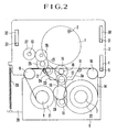
- Fig. 2 is a plan view showing a tape recorder which is arranged as a first embodiment not representing this invention, the tape recorder being shown in a state obtained immediately after loading a tape cassette.
- Fig. 3 is a plan view showing the first embodiment in a state of recording or reproducing signals.
- Fig. 4 is a plan view showing a tape recorder which is arranged as a second embodiment representing the invention, the tape recorder being shown in a state of recording or reproducing signals.
- Fig. 5 is a plan view showing the tape recorder of Fig. 4 in a state obtained immediately after loading a tape cassette.
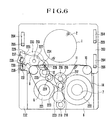
- Fig. 6 is a plan view showing a tape recorder which is arranged as a third embodiment of the invention, the tape recorder being shown in a state obtained immediately after loading a tape cassette.
- Fig. 7 is a plan view showing the tape recorder of Fig. 6 in a state of recording or reproducing signals.
- Fig. 8 is a plan view showing a fourth embodiment of the invention in a recording mode.
- Fig. 9 is a plan view showing the fourth embodiment in a reproducing mode.
- Fig. 10 is a plan view showing the fourth embodiment in a cue mode.
- Fig. 11 is a plan view showing the fourth embodiment in a review mode.
- Fig. 12 is a plan view showing the fourth embodiment in a fast forward mode.
- Fig. 13 is a plan view showing the fourth embodiment in a tape rewinding mode.
- Fig. 2 shows a tape recorder which is arranged as the first embodiment. Tape recorder is shown in a state obtained immediately after the tape recorder is loaded with a tape cassette.
- Fig. 3 shows the same tape recorder in a recording or reproducing state.
- a plurality of magnetic heads 2 are mounted on a head drum 1 respectively in given positions.
- the head drum 1 is arranged to be driven to rotate by a drum driving motor which is not shown.
- the head drum 1 is secured to a movable chassis 3.
- the chassis 3 is arranged to be vertically movable, as viewed in Figs. 2 and 3, through guide slots 4, 30 and 32 which are provided in the chassis 3 and guide pins 5, 31 and 33 which are erected on a stationary chassis 28.
- the chassis 28 is arranged to hold a tape cassette 6.
- a magnetic tape 14 is contained in the tape cassette 6.
- a supply reel 7, a take-up reel 8 and pinch rollers 9 and 10 are arranged within the tape cassette 6.
- the tape cassette 6 is provided further with tape guides 11 and 12 for guiding the tape 14 to a given path on the head drum 1 when the head drum 1 comes into an aperture part 6a provided in the tape cassette 6.
- These tape guides 11 and 12 are respectively disposed on the entrance side and the exit side of the aperture part 6a relative to the head drum 1. Since the pinch rollers 9 and 10 are disposed on the right and left sides of the tape cassette 6, signals can be recorded or reproduced even in cases where the tape is arranged upside down.
- the capstan 13 is arranged to be in pressed contact with the pinch roller 9 across the magnetic tape 14 and thus to cause the magnetic tape 14 to travel toward the take-up reel 8.
- the chassis 3 is urged to move toward the tape cassette 6 by means of a spring 29.
- the spring 29 is arranged to control and set a pressed contact force of the capstan 13 on the pinch roller 9 as will be described in detail later herein.
- a drive transmission system of the tape recorder is described as follows: The reel system and the capstan 13 are arranged to be rotatively driven via a transmission system by means of a driving motor 15 which is disposed on the chassis 3.
- the reel system is connected to the motor 15 in the following manner: A tape take-up action is performed by connecting the motor 15 to a gear 21 on the take-up side or a gear 22 on the supply side through a gear 16 which is mounted on the output side of the driving motor 15, a gear 17, a belt 18, a gear 19 and an idler 20.
- the capstan 13 is likewise connected to the driving motor 15 by the gear 17 through a belt 23 and gears 24, 25 and 26 and a gear 27 which is directly connected to the capstan 13.
- the capstan 13 and the reel system are arranged in this manner to be simultaneously driven by the driving motor 15.
- the movable chassis 3 is constantly pulled by a spring 29 toward the stationary chassis 28.
- the tape recorder is capable of operating to pull up any slack of the tape, to perform a fast forward (FF) action or a fast rewind (FR) action on the magnetic tape 14.
- FF fast forward
- FR fast rewind
- the chassis 3 has been moved to the tape cassette 6 along the guide slots 4, 30 and 32 and the associated guide pins 5, 31 and 33.
- the head drum 1 is located inside of the tape cassette 6.
- the tape 14 is in a state of having been guided to a given traveling path jointly by the tape guides 11 and 12 and the head drum 1.
- the capstan 13 is in pressed contact with the pinch roller 9 to allow the rotation of the driving motor 15 to drive the tape 14.
- the pressed contact force of the capstan 13 exerted on the pinch roller 9 across the tape 14 under this condition is determined by a prescribed urging force of the spring 29.
- the guide slot 4 and the guide pin 5 are stopping the movable chassis 3 from moving further toward the tape cassette 6 on the right side of the chassis 3.
- the abutment on the pinch roller 9 of the capstan 13 is stopping the movable chassis 3 from moving further toward the tape cassette 6.
- capstan 13 and the head drum 1 are arranged on one and the same chassis to prevent them from moving relative to each other. This ensures stability in terms of precision.
- the first embodiment is arranged as described above to use a chassis for holding the head drum and another chassis for holding the tape cassette; to use the urging means (the spring) for urging the two chassis to move toward each other; and to control and set the pressed contact force of the capstan on the pinch roller by using this urging force.
- the arrangement enables the embodiment to ensure a stable tape feeding force without having recourse to any complex structural arrangement.
- a turnable lever is provided on a movable chassis.
- the capstan is disposed on the lever.
- This lever is arranged to be urged to impart a necessary pressed contact force to the capstan.
- Fig. 4 is a plan view of a tape recorder which is arranged as the second embodiment.
- Fig. 4 shows the tape recorder in a recording or reproducing state.
- Fig. 5 shows the same tape recorder as in a state obtained immediately after loading the tape recorder with a tape cassette.
- a cylindrical head drum (hereinafter referred to as the drum) 1 has a plurality of magnetic heads 2 and is arranged to be rotated by a drum driving motor 114a.
- the drum 1 is disposed on a movable chassis 103.
- the chassis 103 is arranged to be movable relative to a tape cassette 6 through guide slots 104 and pins 105 which are erected on a stationary chassis which is not shown but is arranged to carry the tape cassette 6.
- the drum 1 is thus arranged to be inserted into an aperture part 6a provided in the cassette 6 which is carried by the stationary chassis.
- the tape cassette 6 is arranged in the same manner as in the case of the first embodiment. Therefore, the details of the tape cassette 6 are omitted from the following description.
- the drum driving motor 114a is arranged to be coaxial with the drum 1.
- the rotation of the motor 114a is arranged to be transmitted and reduced through an output shaft 114, a belt 115 and gears 116, 117, 118 and 119 to have the capstan 113 driven and rotated by a gear 120 which is connected directly to the capstan 113.
- This rotative driving power applied to the capstan 113 is also transmitted from the gear 120 via gears 121, 122 and 123 and a belt 124, a gear 125, a belt 126, a gear 127 and an idler gear 128 to a reel gear 129 which is disposed on the side of the take-up reel 8 of the tape cassette 6.
- a tape-up action is performed on the tape 14.
- the rotating direction of the motor 114a is reversed.
- the rotating direction of the idler gear 128 is reversed accordingly. This causes the idler gear 128 to revolve around the gear 127 to be connected to a reel gear 130 which is disposed on the side of the supply reel 7 of the tape cassette 6. Therefore, the tape 14 is wound around the supply reel 7.
- the rotation transmitting mechanism ranging from the drum motor 114a to the idler gear 128 is disposed on the movable chassis 103.
- a gear 131 engages the capstan connecting gear 120 together with the gear 119. These gears 119 and 131 are selectively allowed to engage the gear 118.
- the gear 119 is arranged to engage a smaller diameter part of the gear 118.
- the gear 131 is arranged to engage a larger diameter part of the gear 118. This arrangement makes it possible to vary the rotational frequency of the capstan 113 and the reel system without changing the rotational frequency of the drum motor 114a.
- the capstan 113 is disposed on a lever 134 which has its fulcrum arranged to be coaxial with the axis of the gear 121.
- a spring 135 is urging the capstan 113 to move toward the pinch roller 9.
- the pressed contact force of the capstan 113 on the pinch roller 9 is thus determined by the urging force of the spring 135.
- One end of the spring 135 is secured to a hook 136 which is rising from the chassis 103.
- a stopper 137 is arranged on the chassis 103 to restrict the turning movement of the lever 134 toward the pinch roller 9.
- Fig. 5 shows the drum 1 in a state of having been moved away from the tape cassette 6. This state is obtained either immediately after the tape cassette 6 is loaded or in fast forwarding or fast rewinding the tape.
- the turnable lever 134 When the tape recorder is in the state shown in Fig. 5, the turnable lever 134 is under the counterclockwise urging force of the spring 135. However, the turning movement of the lever 134 is restricted by the stopper 137. Therefore, the capstan 113 is not in pressed contact with the pinch roller 9.
- the movable chassis 103 moves downward, as viewed in Fig. 5, along the guide slots 104.
- the drum 1 comes into contact with the tape 14, entering the aperture part 6a of the tape cassette 6.
- the capstan 113 is then brought into pressed contact with the pinch roller 9 through the tape 14.
- the lever 134 is released from its state of being stopped by the stopper 137.
- the pressed contact force of the capstan 113 on the pinch roller 9 is arranged to be determined by the urging force of the spring 135 which is exerted on the turnable lever 134. This arrangement ensures that the pressed contact force can be stably attained even if the mechanical precision of the tape recorder is somewhat degraded.
- Fig. 5 permits the fast tape forwarding (FF) operation or the fast tape rewinding (FR) operation by rotating the drum motor 114 which is a drive source at a higher rotational frequency than in the case of the recording or reproducing state shown in Fig. 4 for increasing the reel system driving speed.
- FF fast tape forwarding
- FR fast tape rewinding
- the tape 14 slackens to a degree as much as the wrapped amount of the tape around the drum 1 when the drum 1 moves away from its position within the tape cassette 6 as shown in Fig. 4 to another position as shown in Fig. 5. It is, therefore, necessary to pull up the slack. Under this condition, if the drum 1 is simply allowed to abruptly begin to rotate at a normal speed, the tape 14 might be damaged by abrupt tape winding which causes an abnormal tape tension. To avoid such a trouble, the rotating speed of the drum 1 is arranged to gradually increase at the start of the rotation in such a way as to prevent occurrence of any sudden increase in tension.
- the pressed contact force of the capstan 113 on the pinch roller 9 is stabilized by means of the spring 135.
- the tape can be transported at a higher speed as the capstan 113 is away from the pinch roller 9.
- the capstan 113 is arranged to be brought into contact or out of contact by moving the movable chassis 103. The timing of bringing the capstan 113 into or out of contact with the pinch roller 9 is ensured to be adequate by simply arranging the stopper 137 on the movable chassis 103.
- the center of turning movement of the lever 134 on which the capstan 113 is disposed is arranged to be coaxial with the axis of rotation of the gear 121 which transmits the driving power to the capstan 113.
- This arrangement precludes the possibility of inadequate transmission of rotation to the capstan 113 due to deviation of turning angle of the lever 134.
- the turning movement of the lever 134 is arranged to be restricted by the stopper 137 which is secured to the movable chassis 103.
- that arrangement may be changed, for example, to arrange some member on the tape cassette carrying chassis to be movable following the movement of the movable chassis 103.
- the capstan 113 is disposed on the turnable lever 134.
- the pressed contact force of the capstan 113 exerted on the pinch roller 9 is determined by the urging force of the urging means (spring) 135.
- This arrangement permits the pressed contact force to be accurately set and ensures a stable tape feeding force.
- the action of bringing the capstan 113 into or out of contact with the pinch roller 9 is arranged to be performed by utilizing the relative movement of the drum 1 and the tape cassette 6. The arrangement, therefore, permits a salient reduction in number of necessary parts.
- a third embodiment representing a second example of this invention is arranged to permit cue and review operations with a compact tape recorder by parting the capstan from the pinch roller while leaving the tape in the state of abutting on the head drum.
- Fig. 6 shows in a plan view the arrangement of a tape recorder which is arranged according to this invention as the third embodiment thereof.
- the tape recorder is shown in a state obtained immediately after loading it with a tape cassette.
- Fig. 7 shows the same tape recorder in a recording or reproducing state.
- a drum 1 which is provided with magnetic heads 2 and the tape cassette 6 are arranged in the same manner as the first and second embodiments described in the foregoing. Therefore the details of the drum 1 and the tape cassette 6 are omitted from the following description.
- the fulcrum 234 of the turning movement of a reel system and the capstan 213 is located on a stationary chassis 232.
- the reel system and the capstan 213 are arranged to be rotatively driven by a driving motor 215 through a transmission system.
- a gear 216 which is mounted on the output shaft of a driving motor 215 is connected either to a gear 221 which is disposed on the side of the take-up reel or a gear 222 which is disposed on the side of the supply reel through a gear 217, a belt 218, a gear 219 and an idler gear 220.
- the gear 217 is connected to a gear 227 which is directly attached to the capstan 213 through a belt 223, gears 224 and 225 and a connection gear 226. This connecting arrangement enables the motor 215 to simultaneously drive the capstan 213 and the reel system.
- the third embodiment is arranged to bring the capstan 213 into or out of contact with the pinch roller 9 in the following manner:
- the capstan 213 is mounted on a turnable lever 228.
- the turning fulcrum 234 of the lever 228 is arranged to be coaxial with the axis of the capstan connecting gear 226 which engages the gear 227 directly attached to the capstan 213.
- a slide lever 229 which is disposed on a movable chassis 203 is arranged to be movable vertically, as viewed in Fig. 6, by means of a mechanism which is not shown.
- a protruding part 237 is erected on the lever 229 and is loosely fitted into a slot 235 which is provided in the lever 228.
- the pressed contact force of the capstan 213 on the pinch roller 9 is arranged to be determined by the urging force of a spring 230.
- the spring 230 is stretched with one end thereof attached to the lever 229 and the other to a protruding part 231 provided on the movable chassis 203.
- the spring 230 determines the pressed contact force of the capstan 213 on the pinch roller 9 by urging the lever 228 to move toward the pinch roller 9 (counterclockwise).
- a plunger 236 is arranged to be energized with a current to push the slide lever 229 in the direction of arrow X in the case of the cue or review operation.
- the lever 228 is turned clockwise by the protruding part 237 of the lever 229, irrespective as to whether the plunger 236 is energized or not, in a direction reverse to the direction of the above-stated pressed contact (toward the tape cassette).
- the capstan 213 is then not brought into contact with the pinch roller 9. Under this condition, any slack of the tape can be pulled up and also the tape recorder can be set in the FF or FR mode in which the tape is to be transported at a high speed. Further, the capstan 213 is provided with a fly-wheel 233.
- the tape recorder can be set in a recording or reproducing mode in the state shown in Fig. 7. However, if the tape recorder is set in a cue or review mode, the plunger 236 is energized with a current. The plunger 236 then causes the slide lever 229 to move in the direction of arrow X. The turnable lever 228 turns in the direction of arrow Y. Therefore, the capstan 213 can be moved away from the pinch roller 9, leaving the tape 14 in the state of being wrapped around the drum 1.
- the tape recorder can be operated in the cue or review mode with the tape transported at a high speed by driving the reel with the driving motor 215.
- the third embodiment is arranged to move the slide lever 229 by means of the plunger 236, the arrangement may be changed to move the slide lever 229 by means of some cam that is arranged to alter its position according to the mode selected.
- the capstan 213 is disposed on the turnable lever 228 and the pressed contact force of the capstan 213 on the pinch roller 209 is arranged to be controllably set by the urging means (spring) 230 to ensure a stable tape feeding force.
- the capstan 213 is movable away from the pinch roller 9 while leaving the tape 14 in the state of being wrapped around the drum 1. Therefore, the tape recorder can be arranged to be operable in various modes without increasing the size of the capstan driving motor.
- the cue or review mode is attained by moving the capstan away from the pinch roller by means of a moving mechanism consisting of the plunger and the slide lever.
- a fourth embodiment representing a third example of the invention is arranged to attain these modes by moving a chassis. The following describes the fourth embodiment with reference to drawings:
- Figs. 8 to 13 show a tape recorder which is arranged as the fourth embodiment of this invention.
- the mechanism of the tape recorder is shown in plan views as in various states obtained in different operation modes.
- the tape cassette to be used by the fourth embodiment is the same as the one used by other embodiments described and thus requires no further description.
- Fig. 8 shows the tape recorder as in a recording state.
- a plurality of magnetic heads which are not shown are mounted on a cylindrical head drum 1.
- a drum driving motor which is not shown is disposed within the head drum 1. This motor serves as a drive source also for reels 7 and 8.
- a stationary chassis 307 is arranged to carry the tape cassette 6.
- a capstan 308 and the head drum 1 are mounted on a movable chassis 309.
- the movable chassis 309 is arranged to be slidable in the longitudinal direction of guide slots 309a to a given distance relative to the stationary chassis 307.
- Guide shafts (or pins) 310 are erected on the stationary chassis 307 and arranged to guide the sliding movement of the movable chassis 309 along a pair of the guide slots 309a.
- a driving gear 311 is arranged to be coaxial with the shaft of the above-stated drum driving motor.
- a change-over mechanism which is not shown is arranged to selectively cause a low speed gear 312 or a high speed gear 313 to engage the driving gear 311.
- An intermediate gear 314 is arranged to selectively engage the low speed gear 312 or the high speed gear 313.
- the mechanism of the tape recorder further includes a rotating direction inverting gear 315; an intermediate gear 316; a gear 315 which is coaxial with the capstan 308; an intermediate gear 318; a gear 319 for a low speed; and a gear 320 for a high speed.
- the intermediate gear 318 is arranged to selectively engage the low speed gear 319 or the high speed gear 320.
- the mechanism also includes an intermediate gear 322; a swing gear 323; a take-up reel connecting gear 324a; a supply reel connecting gear 324b; and gears 325a, 325b, 326a, 326b, 327a and 327b which are arranged to connect the take-up reel and the supply reel for a high speed operation.
- the stationary chassis 307 and the movable chassis 309 are in their first relative positions. Under this condition, the magnetic tape 14 is wrapped a given degree of angle ⁇ around the head drum 1 which has been allowed to enter the aperture part of the tape cassette 6.
- the drum driving motor which is not shown but is disposed within the head drum 1 causes the head drum 1 to rotate in the direction of arrow A, a driving power in the direction of arrow A is imparted to the coaxial driving gear 311.
- the driving power of the motor is transmitted to the gears one after another in the sequence of the gears 311, 313, 314, 316, 317, 318, 319, 321, 322, 323, 324a and 305.
- the magnetic tape 14 is wound around the take-up reel 8.
- the capstan 308 is pushed against the pinch roller 9 which is one of two pinch rollers disposed within the tape cassette 6.
- the capstan 308 thus causes the tape 14 to travel in the direction of arrow B.
- recording can be performed by the magnetic heads which are fixedly mounted on the head drum 1.
- Fig. 9 shows the tape recorder as in a reproducing state.
- the above-stated change-over mechanism causes the low speed gear 312, instead of the high speed gear 313, to engage the driving gear 311.
- the head drum 1 is caused to rotate for reproduction at a speed which is twice as high as its rotating speed for recording. Meanwhile, the rotational frequency transmitted to the capstan 308 is reduced to one half through the gears 311, 312, 314, 316 and 317.
- the magnetic tape 14 then travels in the direction of arrow B at the same speed as the recording speed.
- Figs. 10 and 11 show the tape recorder respectively as in an index forward (cue) state and as in an index reverse (review) state.
- the movable chassis 309 has been moved and guided by the sliding guide shafts 310 within the guide slots 309a, in the direction of arrow D, relative to the stationary chassis 307 (the chassis are in third relative position).
- the tape 14 is wrapped around the head drum 1 a degree of angle ⁇ which is less than the above-stated angle ⁇ .
- some of signals recorded on the tape such as an index signal or the like is readable by the magnetic heads fixedly mounted on the head drum 1.
- the capstan 308 is away from each of the pinch rollers.
- the capstan 308 is then in a position to engage the gears 325a, 325b instead of the gears 324a and 324b.
- the rotating speed of each of the reels is accelerated from the recording or reproducing speed.
- the gear engaging the gears 318 and 321 is arranged to be changeable from the low speed gear 319 over to the high speed gear 320 and vice versa. Under this condition, while the head drum rotating speed remains unchanged, the reel rotating speed is arranged, including the above-stated change-over between the gears 312 and 313, to be selectable from among four different speeds.
- the tape recorder is shown as in the FF mode in Fig. 12 and as in the FR mode in Fig. 13. In these modes, the position of the movable chassis 309 is shifted further in the direction of arrow D relative to the stationary chassis 307 (the second relative position). The head drum 1 is completely separated from the magnetic tape 14. In this instance, the allocation of gears is identical with the gear allocation made in the cue or review mode. Under this condition, the magnetic tape 14 can be transported at a faster speed by increasing the rotating speed of the head drum 1 from the speed for the cue or review mode.
- This embodiment is arranged, as described above, to permit the chassis which carries the head drum and the capstan to be set in any of three positions in relation to another chassis which firmly holds and carries the tape cassette.
- the tape loading mechanism which has heretofore necessitated a complex, highly precise and expensive arrangement can be simplified for cost reduction without impairing the functions of the tape recorder.
Landscapes
- Recording Or Reproducing By Magnetic Means (AREA)
Claims (3)
- Un appareil d'enregistrement ou de reproduction convenant pour enregistrer ou reproduire des signaux sur ou depuis un milieu d'enregistrement en forme de bande, par utilisation d'une cassette ayant un galet de pincement et une paire de bobines à bande autour desquelles le milieu d'enregistrement en forme de bande est enroulé, en tirant le milieu d'enregistrement en forme de bande à l'intérieur de la cassette et en guidant et en provoquant le déplacement du milieu d'enregistrement en forme de bande dans une orientation oblique par rapport à un tambour à tête tournante (1), comprenant :un premier châssis (28, 232, 307) disposé pour maintenir la cassette,un deuxième châssis (3, 103, 309) agencé pour maintenir ledit tambour tournant (1),un mécanisme rotatif destiné à déplacer relativement ledit premier châssis (28, 232, 307) et ledit deuxième châssis (3, 103, 203, 309),un cabestan (113, 213, 308) agencé pour commander le déplacement du milieu d'enregistrement en forme de bande,dans lequel ledit cabestan (113, 213, 308) est monté sur un organe rotatif (134, 228) agencé sur ledit deuxième châssis (3, 103, 203) et cet organe rotatif (134, 228) est déplacé à l'aide d'un moyen de déplacement pour déplacer ledits cabestan (113, 213, 308) dans le sens de la rotation dudit organe rotatif (134, 228) par une force de déplacement exercée par celui-ci, de manière à presser ledit cabestan (113, 213, 308) contre le galet de pincement de la cassette et comprenant en outre une partie de restriction (137, 237) qui n'est pas un guide à bande et qui est agencée pour restreindre le déplacement rotatif dudit organe rotatif.
- Un appareil selon la revendication 1, comprenant en outre une partie de relâchement du contact de pressage conçue pour écarter ledit cabestan (113, 213, 308) du galet de pincement lorsque le milieu d'enregistrement en forme de bande est en déplacement.
- Un appareil selon la revendication 1, dans lequel ledit mécanisme de déplacement est agencé pour commander ledit premier châssis (28, 232, 307) et ledit deuxième châssis (3, 103, 309) pour les placer dans une première position relative dans laquelle des signaux peuvent être enregistrés ou reproduits, le milieu d'enregistrement en forme de bande étant pris en sandwich entre ledit cabestan (113, 213, 308) et le galet de pincement, dans un état où il y a enroulement autour du tambour rotatif (1), dans une deuxième position dans laquelle le milieu d'enregistrement est écarté du tambour rotatif (1) et ledit cabestan (113, 213, 308) est placé à l'écart du galet de pincement, dans une troisième position relative dans laquelle le milieu d'enregistrement est enroulé autour du tambour rotatif (1) sous un angle plus petit que dans la première position et ledit cabestan (113, 213, 308) est placé à l'écart du galet de pincement.
Applications Claiming Priority (8)
| Application Number | Priority Date | Filing Date | Title |
|---|---|---|---|
| JP2312743A JPH04184750A (ja) | 1990-11-20 | 1990-11-20 | 記録または再生装置 |
| JP312743/90 | 1990-11-20 | ||
| JP329861/90 | 1990-11-30 | ||
| JP2329866A JPH04205841A (ja) | 1990-11-30 | 1990-11-30 | 記録または再生装置 |
| JP329866/90 | 1990-11-30 | ||
| JP2329865A JPH04205840A (ja) | 1990-11-30 | 1990-11-30 | 記録または再生装置 |
| JP329865/90 | 1990-11-30 | ||
| JP2329861A JP2694624B2 (ja) | 1990-11-30 | 1990-11-30 | 記録または再生装置 |
Publications (3)
| Publication Number | Publication Date |
|---|---|
| EP0487048A2 EP0487048A2 (fr) | 1992-05-27 |
| EP0487048A3 EP0487048A3 (en) | 1993-09-15 |
| EP0487048B1 true EP0487048B1 (fr) | 1998-07-08 |
Family
ID=27480076
Family Applications (1)
| Application Number | Title | Priority Date | Filing Date |
|---|---|---|---|
| EP91119759A Expired - Lifetime EP0487048B1 (fr) | 1990-11-20 | 1991-11-19 | Appareil d'enregistrement et de reproduction |
Country Status (3)
| Country | Link |
|---|---|
| US (1) | US5355264A (fr) |
| EP (1) | EP0487048B1 (fr) |
| DE (1) | DE69129731T2 (fr) |
Families Citing this family (3)
| Publication number | Priority date | Publication date | Assignee | Title |
|---|---|---|---|---|
| DE69634085T2 (de) * | 1996-10-15 | 2005-12-08 | Hewlett-Packard Development Co., L.P., Houston | Bandantrieb zur Benutzung mit Bandkassetten |
| JP3378779B2 (ja) * | 1997-09-01 | 2003-02-17 | シンワ株式会社 | カセットテーププレーヤ |
| JP2000068259A (ja) * | 1998-08-19 | 2000-03-03 | Tokyo Electron Ltd | 熱処理装置 |
Family Cites Families (13)
| Publication number | Priority date | Publication date | Assignee | Title |
|---|---|---|---|---|
| US4025959A (en) * | 1971-04-05 | 1977-05-24 | Rca Corporation | Recorder-reproducer system |
| CA1008557A (en) * | 1972-03-10 | 1977-04-12 | Henry R. Warren | Recorder-reproducer system |
| US4213162A (en) * | 1977-12-30 | 1980-07-15 | Lemelson Jerome H | Magnetic tape cartridge transducing apparatus and method |
| JPS5671849A (en) * | 1979-11-16 | 1981-06-15 | Canon Inc | Cassette type video tape recorder |
| CH656968A5 (de) * | 1980-12-02 | 1986-07-31 | Gx Holding Ag | Einrichtung zur aufzeichnung und wiedergabe von informationen auf ein bzw. von einem speicherband. |
| NL8501027A (nl) * | 1985-04-09 | 1986-11-03 | Philips Nv | Magneetbandapparaat. |
| JPH0792958B2 (ja) * | 1985-05-27 | 1995-10-09 | ソニー株式会社 | カセツト式記録再生装置 |
| US4803574A (en) * | 1986-02-03 | 1989-02-07 | Matsushita Electric Industrial Co., Ltd. | Arrangement of recording and/or reproducing apparatus |
| US4949203A (en) * | 1987-03-11 | 1990-08-14 | Pioneer Electronic Corporation | Tape recorder having an improved cassette mounting device |
| US4985789A (en) * | 1987-10-02 | 1991-01-15 | Sanyo Electric Co., Ltd. | Signal recording-reproducing apparatus for use with cassette |
| CA1308806C (fr) * | 1988-08-30 | 1992-10-13 | Takefumi Tsuchida | Systeme d'enregistrement-lecture a chassis porte-bobines mobile |
| JP2805920B2 (ja) * | 1989-12-06 | 1998-09-30 | ソニー株式会社 | 回転ヘッド式テーププレーヤ |
| JP2712668B2 (ja) * | 1989-12-06 | 1998-02-16 | ソニー株式会社 | 回転ヘッドを備えたテーププレーヤ |
-
1991
- 1991-11-19 DE DE69129731T patent/DE69129731T2/de not_active Expired - Fee Related
- 1991-11-19 EP EP91119759A patent/EP0487048B1/fr not_active Expired - Lifetime
-
1993
- 1993-11-17 US US08/154,153 patent/US5355264A/en not_active Expired - Fee Related
Also Published As
| Publication number | Publication date |
|---|---|
| US5355264A (en) | 1994-10-11 |
| EP0487048A2 (fr) | 1992-05-27 |
| EP0487048A3 (en) | 1993-09-15 |
| DE69129731T2 (de) | 1999-01-14 |
| DE69129731D1 (de) | 1998-08-13 |
Similar Documents
| Publication | Publication Date | Title |
|---|---|---|
| KR940005849B1 (ko) | 비데오 테이프 레코더의 아이들러 급속 절환 장치 | |
| US5070422A (en) | Magnetic tape back tension device for magnetic recording-reproduction system | |
| US5166843A (en) | Compact helical scan tape recording and/or reproducing apparatus | |
| EP0329181B1 (fr) | Dispositif d'entraînement de supports de bobine | |
| EP0487048B1 (fr) | Appareil d'enregistrement et de reproduction | |
| GB2257560A (en) | A device for altering a tape drive mode | |
| KR100317597B1 (ko) | 자기 기록/재생 장치 | |
| US4951163A (en) | Magnetic recording and reproducing apparatus | |
| US5333807A (en) | Recording and reproducing apparatus having a tape tension changing mechanism | |
| US5428488A (en) | Head drum and tape transport driving device for a video tape recorder | |
| US5196971A (en) | Tape loading mechanism for use in magnetic recording/reproducing apparatus having tape control features for preventing damage to tape | |
| EP0633574B1 (fr) | Appareil d'enregistrement et de reproduction | |
| KR920005245B1 (ko) | 자기테이프 카셋트용 릴 및 테이프 구동장치 | |
| JP2694624B2 (ja) | 記録または再生装置 | |
| JP2002230868A (ja) | テープドライブ装置 | |
| JP2512930B2 (ja) | テ−プ駆動装置 | |
| JP2954739B2 (ja) | 磁気記録再生装置のカム操作機構 | |
| JP2538449B2 (ja) | 磁気テ―プ引き出し装置 | |
| KR0113203Y1 (ko) | 자기기록재생기의 테이프 고속 주행장치 | |
| JP2958973B2 (ja) | 磁気記録再生装置 | |
| JPS5880161A (ja) | 磁気記録再生装置 | |
| JPH04205841A (ja) | 記録または再生装置 | |
| JPH04205840A (ja) | 記録または再生装置 | |
| JPH0423337B2 (fr) | ||
| JPH02187956A (ja) | ローデイング機構 |
Legal Events
| Date | Code | Title | Description |
|---|---|---|---|
| PUAI | Public reference made under article 153(3) epc to a published international application that has entered the european phase |
Free format text: ORIGINAL CODE: 0009012 |
|
| AK | Designated contracting states |
Kind code of ref document: A2 Designated state(s): DE ES FR GB IT NL |
|
| PUAL | Search report despatched |
Free format text: ORIGINAL CODE: 0009013 |
|
| PUAF | Information related to the publication of a search report (a3 document) modified or deleted |
Free format text: ORIGINAL CODE: 0009199SEPU |
|
| AK | Designated contracting states |
Kind code of ref document: A3 Designated state(s): DE ES FR GB IT NL |
|
| D17D | Deferred search report published (deleted) | ||
| PUAL | Search report despatched |
Free format text: ORIGINAL CODE: 0009013 |
|
| AK | Designated contracting states |
Kind code of ref document: A3 Designated state(s): DE ES FR GB IT NL |
|
| 17P | Request for examination filed |
Effective date: 19940201 |
|
| 17Q | First examination report despatched |
Effective date: 19960117 |
|
| GRAG | Despatch of communication of intention to grant |
Free format text: ORIGINAL CODE: EPIDOS AGRA |
|
| GRAG | Despatch of communication of intention to grant |
Free format text: ORIGINAL CODE: EPIDOS AGRA |
|
| GRAH | Despatch of communication of intention to grant a patent |
Free format text: ORIGINAL CODE: EPIDOS IGRA |
|
| GRAH | Despatch of communication of intention to grant a patent |
Free format text: ORIGINAL CODE: EPIDOS IGRA |
|
| GRAA | (expected) grant |
Free format text: ORIGINAL CODE: 0009210 |
|
| AK | Designated contracting states |
Kind code of ref document: B1 Designated state(s): DE ES FR GB IT NL |
|
| PG25 | Lapsed in a contracting state [announced via postgrant information from national office to epo] |
Ref country code: ES Free format text: THE PATENT HAS BEEN ANNULLED BY A DECISION OF A NATIONAL AUTHORITY Effective date: 19980708 Ref country code: FR Free format text: LAPSE BECAUSE OF FAILURE TO SUBMIT A TRANSLATION OF THE DESCRIPTION OR TO PAY THE FEE WITHIN THE PRESCRIBED TIME-LIMIT Effective date: 19980708 Ref country code: IT Free format text: LAPSE BECAUSE OF FAILURE TO SUBMIT A TRANSLATION OF THE DESCRIPTION OR TO PAY THE FEE WITHIN THE PRE;WARNING: LAPSES OF ITALIAN PATENTS WITH EFFECTIVE DATE BEFORE 2007 MAY HAVE OCCURRED AT ANY TIME BEFORE 2007. THE CORRECT EFFECTIVE DATE MAY BE DIFFERENT FROM THE ONE RECORDED.SCRIBED TIME-LIMIT Effective date: 19980708 |
|
| REF | Corresponds to: |
Ref document number: 69129731 Country of ref document: DE Date of ref document: 19980813 |
|
| PG25 | Lapsed in a contracting state [announced via postgrant information from national office to epo] |
Ref country code: GB Free format text: LAPSE BECAUSE OF NON-PAYMENT OF DUE FEES Effective date: 19981119 |
|
| EN | Fr: translation not filed | ||
| PLBE | No opposition filed within time limit |
Free format text: ORIGINAL CODE: 0009261 |
|
| STAA | Information on the status of an ep patent application or granted ep patent |
Free format text: STATUS: NO OPPOSITION FILED WITHIN TIME LIMIT |
|
| 26N | No opposition filed | ||
| GBPC | Gb: european patent ceased through non-payment of renewal fee |
Effective date: 19981119 |
|
| PGFP | Annual fee paid to national office [announced via postgrant information from national office to epo] |
Ref country code: NL Payment date: 20031105 Year of fee payment: 13 |
|
| PGFP | Annual fee paid to national office [announced via postgrant information from national office to epo] |
Ref country code: DE Payment date: 20031127 Year of fee payment: 13 |
|
| PG25 | Lapsed in a contracting state [announced via postgrant information from national office to epo] |
Ref country code: DE Free format text: LAPSE BECAUSE OF NON-PAYMENT OF DUE FEES Effective date: 20050601 Ref country code: NL Free format text: LAPSE BECAUSE OF NON-PAYMENT OF DUE FEES Effective date: 20050601 |
|
| NLV4 | Nl: lapsed or anulled due to non-payment of the annual fee |
Effective date: 20050601 |