EP0486843B1 - Handwerkzeugmaschine mit Bremskupplung - Google Patents
Handwerkzeugmaschine mit Bremskupplung Download PDFInfo
- Publication number
- EP0486843B1 EP0486843B1 EP91118288A EP91118288A EP0486843B1 EP 0486843 B1 EP0486843 B1 EP 0486843B1 EP 91118288 A EP91118288 A EP 91118288A EP 91118288 A EP91118288 A EP 91118288A EP 0486843 B1 EP0486843 B1 EP 0486843B1
- Authority
- EP
- European Patent Office
- Prior art keywords
- machine tool
- hand machine
- spring
- brake
- switch
- Prior art date
- Legal status (The legal status is an assumption and is not a legal conclusion. Google has not performed a legal analysis and makes no representation as to the accuracy of the status listed.)
- Expired - Lifetime
Links
Images


Classifications
-
- B—PERFORMING OPERATIONS; TRANSPORTING
- B23—MACHINE TOOLS; METAL-WORKING NOT OTHERWISE PROVIDED FOR
- B23Q—DETAILS, COMPONENTS, OR ACCESSORIES FOR MACHINE TOOLS, e.g. ARRANGEMENTS FOR COPYING OR CONTROLLING; MACHINE TOOLS IN GENERAL CHARACTERISED BY THE CONSTRUCTION OF PARTICULAR DETAILS OR COMPONENTS; COMBINATIONS OR ASSOCIATIONS OF METAL-WORKING MACHINES, NOT DIRECTED TO A PARTICULAR RESULT
- B23Q11/00—Accessories fitted to machine tools for keeping tools or parts of the machine in good working condition or for cooling work; Safety devices specially combined with or arranged in, or specially adapted for use in connection with, machine tools
- B23Q11/0078—Safety devices protecting the operator, e.g. against accident or noise
- B23Q11/0092—Safety devices protecting the operator, e.g. against accident or noise actuating braking or stopping means
-
- B—PERFORMING OPERATIONS; TRANSPORTING
- B25—HAND TOOLS; PORTABLE POWER-DRIVEN TOOLS; MANIPULATORS
- B25B—TOOLS OR BENCH DEVICES NOT OTHERWISE PROVIDED FOR, FOR FASTENING, CONNECTING, DISENGAGING OR HOLDING
- B25B23/00—Details of, or accessories for, spanners, wrenches, screwdrivers
- B25B23/14—Arrangement of torque limiters or torque indicators in wrenches or screwdrivers
- B25B23/141—Mechanical overload release couplings
-
- B—PERFORMING OPERATIONS; TRANSPORTING
- B25—HAND TOOLS; PORTABLE POWER-DRIVEN TOOLS; MANIPULATORS
- B25D—PERCUSSIVE TOOLS
- B25D16/00—Portable percussive machines with superimposed rotation, the rotational movement of the output shaft of a motor being modified to generate axial impacts on the tool bit
- B25D16/003—Clutches specially adapted therefor
-
- B—PERFORMING OPERATIONS; TRANSPORTING
- B25—HAND TOOLS; PORTABLE POWER-DRIVEN TOOLS; MANIPULATORS
- B25F—COMBINATION OR MULTI-PURPOSE TOOLS NOT OTHERWISE PROVIDED FOR; DETAILS OR COMPONENTS OF PORTABLE POWER-DRIVEN TOOLS NOT PARTICULARLY RELATED TO THE OPERATIONS PERFORMED AND NOT OTHERWISE PROVIDED FOR
- B25F5/00—Details or components of portable power-driven tools not particularly related to the operations performed and not otherwise provided for
- B25F5/001—Gearings, speed selectors, clutches or the like specially adapted for rotary tools
-
- F—MECHANICAL ENGINEERING; LIGHTING; HEATING; WEAPONS; BLASTING
- F16—ENGINEERING ELEMENTS AND UNITS; GENERAL MEASURES FOR PRODUCING AND MAINTAINING EFFECTIVE FUNCTIONING OF MACHINES OR INSTALLATIONS; THERMAL INSULATION IN GENERAL
- F16D—COUPLINGS FOR TRANSMITTING ROTATION; CLUTCHES; BRAKES
- F16D67/00—Combinations of couplings and brakes; Combinations of clutches and brakes
- F16D67/02—Clutch-brake combinations
- F16D67/06—Clutch-brake combinations electromagnetically actuated
Definitions
- the invention is based on a hand tool according to the preamble of claim 1.
- a wrap spring for braking the housing of a hand tool that is suddenly accelerated by a blocked tool.
- the wrap spring is switched by an inertial mass against which the housing of the machine rotates.
- the mass of inertia takes up a lot of space and is very heavy.
- the effectiveness of the inertial mass is significantly reduced by bearing friction and the friction of a necessary spring-loaded locking pin.
- a wrap spring clutch is known from US 3,228,497, which can be actuated by means of an electromagnetic brake.
- This wrap spring clutch is used to stop / switch through a drive shaft when the power supply is interrupted.
- the electromagnetic brake is biased in the direction of its braking position by means of a spring, so that an associated coil for transmitting a torque must be constantly energized, which causes high energy losses in particular in continuous operation and leads to undesired heating.
- a hand tool which has a clutch designed as a wrap spring clutch.
- the wrap spring clutch is used to switch on or off a striking mechanism of the hand tool.
- the hand tool according to the invention according to the characterizing features of claim 1 has the advantage, in contrast, to be provided with an electronically activatable brake clutch, which ensures a reliable and quickly responsive coupling of the drive shaft and housing when the tool is blocked.
- the brake clutch can be activated by means of a detection device which, in the event of a blockage, effectively prevents the rotation of the housing about the drive shaft.
- the measures listed in the subclaims enable advantageous developments and improvements of the hand-held power tool specified in claim 1. It is particularly advantageous to arrange the electromagnetic brake in such a way that it does not require any activation energy during normal operation of the hand power tool. In addition, it is advantageous to provide the hand-held power tool with a freewheel lock, since reverse torques can then be transmitted from the tool to the drive train. Furthermore, an overload detector switches off the drive motor in the event of unfavorable operating conditions.
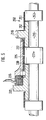
- Figure 1 shows an overall view of a rotary hammer
- Figure 2 shows a cross section along line II-II in Figure 1
- Figure 3 shows a partial section III-III in Figure 2.
- Figure 4 shows a second
- Figure 5 shows a third embodiment.
- a hand-held power tool designed as a hammer drill has an outer housing 1, preferably made of plastic, to which a housing 2 for holding the internal components of the hammer drill is firmly connected.
- an electric motor 3 is housed, which is in gear connection with an intermediate shaft 4.
- the intermediate shaft 4 is in turn connected via a switching mechanism 5 to a hammer tube 6, on which a tool holder 7 is placed.
- a tool 8 can be inserted into the tool holder 7.
- a striking mechanism 10 which is known per se and is not shown in all details is driven by the intermediate shaft 4.
- FIG. 3 shows a reciprocatingly driven pot piston 11, a racket 12 guided therein and a striker 13 acted upon by the racket 12. The striker 13 exerts axial impacts on the shank of the tool 8 during operation.
- the intermediate shaft 4 which is roller-mounted in the housing, carries a pinion 15 and serves the switching mechanism 5 as a drive shaft.
- the hammer tube 6, which is non-rotatably connected to a gear 16, serves as the output shaft.
- the rear derailleur 5 has a drive hub 18 which meshes with the pinion 15.
- a gear shaft 19 is in constant engagement with the toothed wheel 16 of the hammer tube 6 with its toothing 20.
- the drive hub 18 is freely rotatable on the output hub 19.
- An output hub 21 is rotatably connected to the selector shaft 19.
- a switching spring 22 is looped under pre-tension, which non-positively connects the two hubs according to the principle of cable friction. Their winding direction corresponds to the direction of rotation of the drive hub 18.
- Drive hub 18, output hub 21 and shift spring 22 together form a switchable wrap spring clutch in the drive train between Electric motor 3 and tool holder 7.
- a radially outwardly protruding end 23 of the switching spring 22 engages in a recess 24 in a switching sleeve 25 surrounding the switching spring 22, so that the switching spring 22 is connected to the switching sleeve 25 in a form-fitting, rotationally fixed manner.
- the output hub 21 has a front hub section 27, against which the switching spring 22 rests, and a rear hub section 28, against which a brake spring 30, also designed as a wrap spring, bears under pretension.
- the brake spring 30 is additionally positively connected to the output hub 21 by its end 31 projecting inwards into the rear hub section 28. In axial extension to the output hub 21, this is followed by a housing hub 32, which, however, has a smaller outer diameter than the rear hub section 28.
- the output hub 21 and the selector shaft 19 are freely rotatable relative to the housing hub 32.
- the selector shaft 19 is rotatably mounted in the housing hub 32 and the housing 2 by means of needle bearings.
- the brake spring 30 surrounds the housing hub 32 without touching it.
- the housing-side end 33 of the brake spring 30 engages in a recess 34 in the switching sleeve 25.
- Output hub 21, brake spring 30 and housing hub 32 together form a switchable wrap spring clutch which, in the closed state (not shown), couples the selector shaft 19 and thus the tool 7 to the housing 2 in a rotationally fixed manner.
- An electromagnetic brake 36 is fastened in a rotationally fixed manner to the housing hub 32.
- the brake 36 has a coil 37 and a non-ferromagnetic brake plate 38 as a brake lining.
- the coil 37 can be energized via connection cable 39.
- the brake plate 38 lies with a small gap opposite a braking surface 40 on the switching sleeve 25.
- the housing hub 32 is in turn screwed to the housing 2.
- the entire switching mechanism 5 with its parts 18 to 40 forms a unit which can be inserted into the housing 2 like a cartridge and forms part of the drive train between the motor 3 and the tool holder 7 of the hammer drill 1.
- An overload detector (not shown) can be arranged on the electric motor 3, which causes the motor 3 to be switched off if the motor current is too high due to one of the clutches 18, 21, 22 or 21, 30, 32 slipping or closing.
- the intermediate shaft 4 is driven by the electric motor 3 in a constantly rotating manner.
- the rotary movement is transmitted to the drive hub 18 of the switching mechanism 5, which is also driven in a constantly rotating manner.
- the output hub 21 is non-positively connected to the drive hub 18 via the prestressed switching spring 22.
- the switching spring 22 wraps around both the outer diameter of the drive hub and the outer diameter of the driven hub 21 under pretension.
- the winding direction of the switching spring 22 is selected such that the rotation of the drive hub causes an increase in the contact pressure of the spring on the hubs.
- the rotary movement is transmitted from the output hub 21 to the gearwheel 16 of the hammer tube 6 via the selector shaft 19, which is firmly connected to it, and its toothing 20 and serves to drive the tool 8 in rotation.
- the switching sleeve 25 is also rotated continuously.
- the brake spring 30, which is preloaded on the rear hub section 28, is also rotated continuously. During normal operation, the brake spring 30 is not connected to the stationary housing hub 32.
- the switching sleeve 25 When the switching sleeve 25 is braked, it simultaneously rotates the brake spring 30 in the direction of its winding direction in such a way that the brake spring 30 positively engages the housing hub 32. As a result, the control shaft 19 connected to the tool is stopped in relation to the housing 2 in a short time. This means that the housing cannot turn around the tool 8 and slips out of the hand of the operator, but in most cases the hooked tool is torn away again from the masonry or the workpiece.
- the electric motor 3 can continue to run or run out and only drives the idling drive hub 18, which rotates with respect to the selector shaft 19.
- the rotary drive of the tool can also be switched off.
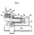
- the second exemplary embodiment according to FIG. 4 shows a series connection compared to the parallel connection of the wrap springs from the first exemplary embodiment. Components of the same type are identified by reference numbers increased by 100.
- the rear derailleur 105 has a drive hub 118 which is rotatably mounted on a selector shaft 119.
- An output hub 121 is non-rotatably connected to the selector shaft 119, in which a selector spring 122 engages in a form-fitting manner.
- the switching spring 122 wraps around the hub 121 on its circumference. In its further course, the switching spring 122 wraps around the drive hub 118.
- the second end 123 of the switching spring 122 projects into a transmission ring 100, into which an end 131 of a brake spring 130 also projects.
- the transmission ring 100 connects the two spring ends 123, 131 in a form-fitting manner.
- the second end 132 of the brake spring 130 is positively connected to a switching sleeve 125.
- a housing hub 132 projects into the interior of the brake spring 130 without touching the brake spring during the rotary drive of the tool holder (not shown in FIG. 4).
- An electromagnetic brake 136 with a coil 137 and a non-ferromagnetic brake plate 138 as a brake pad, which is opposite a braking surface 140 of the shift sleeve 125, is seated on the housing hub 132, which is firmly connected to the housing.
- brake 136 is triggered, as in the first exemplary embodiment, and brakes shift sleeve 125, which rotates during operation.
- the brake spring 130 and the transmission ring 100 are also braked with respect to the selector shaft 119.
- the brake spring 130 narrows and loops around the housing hub 132.
- the switching shaft 119 which is rotatably connected to the tool holder, is thus non-positively connected to the housing, so that the housing no longer rotates around the blocked tool can.
- the switching mechanism 205 is constructed in its core just like the first exemplary embodiment.
- the corresponding components are identified by reference numbers increased by 200.
- these are drive hub 218, selector shaft 219, output hub 221, selector spring 222, selector sleeve 225, brake spring 230, housing hub 232 and an electromagnetic brake 236.
- clutch 218, 221, 222 is also equipped with a freewheel lock 250.
- This consists of a further wrap spring 251, which is wound with a winding direction opposite to the switching spring 222 under pretension on the drive hub 218 and the switching shaft 219.
- the drive hub 218 carries an additional hub section 252 and the selector shaft 219 has an additional collar 253 with the same outer diameter as the hub section 252.
- This embodiment has the advantage that reverse torques which are introduced into the drive train by the tool can be transmitted from the wrap spring 251 to the selector shaft 219.
- the switching spring 222 would not be able to do this, since wrap springs can only transmit significant moments in one direction of rotation. If the brake 236 is triggered, the switching spring 222 is released as in the first exemplary embodiment, while the wrap spring 251 is subjected to the direction of rotation which transmits its moments and slips on the hub section 252 under the collar 253.
Landscapes
- Engineering & Computer Science (AREA)
- Mechanical Engineering (AREA)
- General Engineering & Computer Science (AREA)
- Physics & Mathematics (AREA)
- Electromagnetism (AREA)
- Percussive Tools And Related Accessories (AREA)
Description
- Die Erfindung geht aus von einer Handwerkzeugmaschine nach der Gattung des Anspruchs 1. Aus der DE-OS 38 02 740 ist bekannt, eine Schlingfeder zum Abbremsen des durch ein blockiertes Werkzeug plötzlich beschleunigten Gehäuses einer Handwerkzeugmaschine zu verwenden. Dabei wird die Schlingfeder durch eine träge Masse geschaltet, gegenüber der sich das Gehäuse der Maschine verdreht. Die Trägheitsmasse hat einen großen Platzbedarf und weist ein erhebliches Gewicht auf. Außerdem wird die Wirksamkeit der Trägheitsmasse durch Lagerreibung und die Reibung eines notwendigen federbelasteten Rastbolzens erheblich verringert.
- Weiterhin ist aus der US 3,228,497 eine Schlingfederkupplung bekannt, die mittels einer elektromagnetischen Bremse betätigbar ist. Diese Schlingfederkupplung dient zum Stoppen/Durchschalten einer Antriebswelle bei Unterbrechung der Stromzufuhr. Die elektromagetische Bremse ist mittels einer Feder in Richtung ihrer Bremsstellung vorgespannt, so daß eine zugehörige Spule zur Übertragung eines Drehmoments ständig bestromt sein muß, was insbesondere im Dauerbetrieb hohe Energieverluste verursacht und zu einer unerwünschten Erwärmung führt.
- Aus der DE 37 31 244 A1 ist eine Handwerkzeugmaschine bekannt, die eine als Schlingfederkupplung ausgeführte Schaltkupplung aufweist. Die Schlingfederkupplung dient dabei dem Zu- oder Abschalten eines Schlagwerks der Handwerkzeugmaschine.
- Die erfindungsgemäße Handwerkzeugmaschine gemäß den kennzeichnenden Merkmalen des Anspruchs 1 hat demgegenüber den Vorteil, mit einer elektronisch aktivierbaren Bremskupplung versehen zu sein, die im Blockierfall des Werkzeugs für eine zuverlässige und schnell ansprechende Kupplung von Antriebswelle und Gehäuse sorgt. Die Bremskupplung ist hierzu mittels einer Detektionseinrichtung aktivierbar, die im Blockierfall die Rotation des Gehäuses um die Antriebswelle wirksam unterbindet.
- Durch die in den Unteransprüchen aufgeführten Maßnahmen sind vorteilhafte Weiterbildungen und Verbesserungen der im Anspruch 1 angegebenen Handwerkzeugmaschine möglich. Besonders vorteilhaft ist es, die elektromagnetische Bremse derart anzuordnen, daß sie im Normalbetrieb der Handwerkzeugmaschine keine Aktivierungsenergie benötigt. Darüber hinaus ist es vorteilhaft, die Handwerkzeugmaschine mit einer Freilaufsperre zu versehen, da dann Rückdrehmomente vom Werkzeug in den Antriebsstrang übertragen werden können. Des weiteren bewirkt ein Überlastdetektor bei ungünstigen Betriebszuständen eine Abschaltung des Antriebsmotors.
- Ein Ausführungsbeispiel der Erfindung ist in der Zeichnung dargestellt und in der nachfolgenden Beschreibung näher erläutert. Figur 1 zeigt eine Gesamtansicht eines Bohrhammers, Figur 2 zeigt einen Querschnitt gemäß Linie II-II in Figur 1, und Figur 3 zeigt einen Teilschnitt III-III in Figur 2. Figur 4 zeigt ein zweites und Figur 5 ein drittes Ausführungsbeispiel.
- Eine als Bohrhammer ausgeführte Handwerkzeugmaschine hat ein vorzugsweise aus Kunststoff gefertiges Außengehäuse 1, mit dem ein Gehäuse 2 zur Halterung der inneren Bauteile des Bohrhammers fest verbunden ist. In dem Gehäuse 2 ist ein Elektromotor 3 untergebracht, der in Getriebeverbindung mit einer Zwischenwelle 4 steht. Die Zwischenwelle 4 steht ihrerseits über ein Schaltwerk 5 mit einem Hammerrohr 6 in Getriebeverbindung, auf das ein Werkzeughalter 7 aufgesetzt ist. In den Werkzeughalter 7 ist ein Werkzeug 8 einsetzbar. Weiter ist von der Zwischenwelle 4 ein an sich bekanntes und nicht in allen Einzelheiten gezeigtes Schlagwerk 10 angetrieben. In Figur 3 ist davon ein hin- und hergehend angetriebener Topfkolben 11, ein darin geführter Schläger 12 und ein von dem Schläger 12 beaufschlagter Döpper 13 ersichtlich. Der Döpper 13 übt im Betrieb axiale Schläge auf den Schaft des Werkzeugs 8 aus.
- Die im Gehäuse wälzgelagerte Zwischenwelle 4 trägt ein Ritzel 15 und dient dem Schaltwerk 5 als Antriebswelle. Als Abtriebswelle dient das Hammerrohr 6, das mit einem Zahnrad 16 drehfest verbunden ist.
- Das Schaltwerk 5 weist eine Antriebsnabe 18 auf, die mit dem Ritzel 15 kämmt. Eine Schaltwelle 19 steht mit ihrer Verzahnung 20 in ständigem Eingriff mit dem Zahnrad 16 des Hammerrohrs 6. Die Antriebsnabe 18 ist auf der Abtriebsnabe 19 frei drehbar. Mit der Schaltwelle 19 ist eine Abtriebsnabe 21 drehfest verbunden. Um die Außendurchmesser von Antriebsnabe 18 und Abtriebsnabe 21 ist unter Vorspannung eine Schaltfeder 22 geschlungen, die nach dem Prinzip der Seilreibung die beiden Naben kraftschlüssig verbindet. Ihr Windungssinn entspricht der Drehrichtung der Antriebsnabe 18. Antriebsnabe 18, Abtriebsnabe 21 und Schaltfeder 22 bilden zusammen eine schaltbare Schlingfederkupplung in dem Antriebsstrang zwischen Elektromotor 3 und Werkzeughalter 7. Ein radial nach außen abstehendes Ende 23 der Schaltfeder 22 greift in eine Aussparung 24 einer die Schaltfeder 22 umgebenden Schalthülse 25 ein, so daß die Schaltfeder 22 formschlüssig drehfest mit der Schalthülse 25 verbunden ist. Die Abtriebsnabe 21 hat einen vorderen Nabenabschnitt 27, an dem die Schaltfeder 22 anliegt, und einen hinteren Nabenabschnitt 28, an dem eine ebenfalls als Schlingfeder ausgebildete Bremsfeder 30 unter Vorspannung anliegt. Die Bremsfeder 30 ist zusätzlich mit ihrem nach innen in den hinteren Nabenabschnitt 28 hineinragenden Ende 31 formschlüssig mit der Abtriebsnabe 21 verbunden. In axialer Verlängerung zu der Abtriebsnabe 21 schließt sich an diese eine Gehäusenabe 32 an, die jedoch einen geringeren Außendurchmesser aufweist als der hintere Nabenabschnitt 28. Die Abtriebsnabe 21 sowie die Schaltwelle 19 sind gegenüber der Gehäusenabe 32 frei drehbar. Die Schaltwelle 19 ist mittels Nadellagern in der Gehäusenabe 32 und dem Gehäuse 2 drehbar gelagert. Die Bremsfeder 30 umgibt die Gehäusenabe 32, ohne sie zu berühren. Das gehäuseseitige Ende 33 der Bremsfeder 30 greift in eine Aussparung 34 der Schalthülse 25 ein. Abtriebsnabe 21, Bremsfeder 30 und Gehäusenabe 32 bilden zusammen eine schaltbare Schlingfederkupplung, die in nicht gezeigtem geschlossenen Zustand die Schaltwelle 19 und damit das Werkzeug 7 drehfest an das Gehäuse 2 koppelt.
- An der Gehäusenabe 32 ist drehfest eine elektromagnetische Bremse 36 befestigt. Die Bremse 36 weist eine Spule 37 und eine nicht ferromagnetische Bremsplatte 38 als Bremsbelag auf. Die Spule 37 kann über Anschlußkabel 39 unter Strom gesetzt werden. Die Bremsplatte 38 liegt mit einem geringen Spalt einer Bremsfläche 40 an der Schalthülse 25 gegenüber. Die Gehäusenabe 32 ist ihrerseits fest mit dem Gehäuse 2 verschraubt. Das gesamte Schaltwerk 5 mit seinen Teilen 18 bis 40 bildet eine Einheit, die patronenartig in das Gehäuse 2 einsetzbar ist und einen Teil des Antriebsstranges zwischen Motor 3 und Werkzeughalter 7 des Bohrhammers 1 bildet.
- An dem Elektromotor 3 kann ein nicht gezeigter Überlastdetektor angeordnet sein, der bei zu hohem Motorstrom infolge Durchrutschen bzw. Schließen einer der Kupplungen 18, 21, 22 bzw. 21, 30, 32 eine Abschaltung des Motors 3 bewirkt.
- Im Betrieb des Bohrhammers wird die Zwischenwelle 4 vom Elektromotor 3 ständig drehend angetrieben. Über das Ritzel 15 der Zwischenwelle wird die Drehbewegung auf die Antriebsnabe 18 des Schaltwerks 5 übertragen, die ebenfalls ständig drehend angetrieben ist. Mit der Antriebsnabe 18 ist die Abtriebsnabe 21 über die vorgespannte Schaltfeder 22 kraftschlüssig verbunden. Die Schaltfeder 22 umschlingt unter Vorspannung sowohl den Außendurchmesser der Antriebsnabe als auch den Außendurchmesser der Abtriebsnabe 21. Der Windungssinn der Schaltfeder 22 ist so gewählt, daß die Drehung der Antriebsnabe eine Erhöhung des Anpreßdrucks der Feder an die Naben bewirkt. Die Drehbewegung wird von der Abtriebsnabe 21 über die fest mit ihr verbundene Schaltwelle 19 und deren Verzahnung 20 an das Zahnrad 16 des Hammerrohrs 6 übertragen und dient dem drehenden Antrieb des Werkzeugs 8.
- Mit den Naben 18, 21 und der Schaltfeder 22 wird auch die Schalthülse 25 dauernd mitgedreht. Ebenfalls dauernd mitgedreht wird die auf den hinteren Nabenabschnitt 28 vorgespannte Bremsfeder 30. Während des Normalbetriebs besteht keine Verbindung der Bremsfeder 30 mit der stillstehenden Gehäusenabe 32.
- Ein Blockieren des Werkzeug 8 im Werkstück, d.h. ein plötzliches Abbremsen des Werkzeugs und ruckhaftes Beschleunigen des Gehäuses 1,2 wird durch eine nicht näher gezeigte Detektionseinrichtung erkannt. Diese schließt den Stromkreis durch die Spule 37 der elektromagnetischen Bremse 36. Die durch den Elektromagneten 37 bewirkte Anziehung der sich drehenden Schalthülse 25 bewirkt deren Abbremsung. Bei Betätigung der Bremse dient die Bremsplatte 38 bei ihrer Berührung mit der Bremsfläche 40 als Verschleißfläche. Die abgebremste Schalthülse 25 verdreht das Ende 23 der Schaltfeder 22 gegen ihren Windungssinn, so daß die kraftschlüssige Verbindung der Schaltfeder 22 mit den Naben 18, 21 aufgehoben wird. Das von einer Kupplungshälfte übertragbare Moment MT berechtet sich nach

mit - Mo
- = Vorspannmoment der Schlingfeder über einer der Reibflächen in Nm
- µ
- = Reibungskoeffizient, dimensionslos
- φ
- = Umschlingungswinkel pro Reibfläche in rad.
- Das heißt die kraftschlüssige Verbindung der Schaltfeder 22 mit den Naben 18, 21 wird aufgehoben, sobald das Vorspannmoment Mo Null wird.
- Beim Abbremsen der Schalthülse 25 verdreht diese gleichzeitig die Bremsfeder 30 in Richtung ihres Windungssinns so, daß sich die Bremsfeder 30 kraftschlüssig an die Gehäusenabe 32 anlegt. Dadurch wird in kurzer Zeit die mit dem Werkzeug in Verbindung stehende Schaltwelle 19 gegenüber dem Gehäuse 2 stillgesetzt. Dies führt dazu, daß das Gehäuse sich nicht um das Werkzeug 8 herumdrehen kann und der Hand der Bedienungspersonen entgleitet, sondern in den meisten Fällen das verhakte Werkzeug wieder aus dem Mauerwerk oder dem Werkstück losgerissen wird. Der Elektromotor 3 kann währenddessen weiter- beziehungsweise auslaufen und treibt lediglich noch die leerlaufende und sich gegenüber der Schaltwelle 19 drehende Antriebsnabe 18 an.
- Wird die Bremse 36 willkürlich durch einen dafür vorgesehenen Schalter während des Betriebs betätigt, so läßt sich damit auch der Drehantrieb des Werkzeugs abschalten.
- Das zweite Ausführungsbeispiel gemäß Figur 4 zeigt gegenüber der Parallelschaltung der Schlingfedern aus dem ersten Ausführungsbeispiel eine Reihenschaltung. Gleichartige Bauteile sind mit um 100 erhöhten Bezugszahlen bezeichnet. Das Schaltwerk 105 hat eine Antriebsnabe 118, die drehbar auf einer Schaltwelle 119 gelagert ist. Mit der Schaltwelle 119 ist drehfest eine Abtriebsnabe 121 verbunden, in die formschlüssig eine Schaltfeder 122 eingreift. Außerdem umschlingt die Schaltfeder 122 die Nabe 121 an ihrem Umfang. In ihrem weiteren Verlauf umschlingt die Schaltfeder 122 die Antriebsnabe 118. Das zweite Ende 123 der Schaltfeder 122 ragt in einen Übertragungsring 100 hinein, in den gleichzeitig auch ein Ende 131 einer Bremsfeder 130 hineinragt. Der Übertragungsring 100 verbindet die beiden Federenden 123, 131 formschlüssig. Das zweite Ende 132 der Bremsfeder 130 ist formschlüsssig mit einer Schalthülse 125 verbunden. Ins Innere der Bremsfeder 130 ragt eine Gehäusenabe 132 hinein, ohne die Bremsfeder während des Drehantriebs des in Figur 4 nicht gezeigten Werkzeughalters zu berühren. Auf der mit dem Gehäuse fest verbundenen Gehäusenabe 132 sitzt eine elektromagnetische Bremse 136 mit Spule 137 und einer nicht ferromagnetischen Bremsplatte 138 als Bremsbelag, die einer Bremsfläche 140 der Schalthülse 125 gegenüberliegt.
- Im Blockierfall wird wie im ersten Ausführungsbeispiel die Bremse 136 ausgelöst und bremst die während des Betriebs mitdrehende Schalthülse 125 ab. Damit wird auch die Bremsfeder 130 sowie der Übertragungsring 100 gegenüber der Schaltwelle 119 abgebremst. Durch das damit verbundene Abbremsen des Federendes 123 der Schaltfeder 122 wird diese aufgeweitet, sie löst sich von der Antriebsnabe 118 und das Vorspannmoment Mo fällt weg. Damit ist der Antriebsstrang zwischen Motor und Werkzeughalter unterbrochen. Im weiteren Verlauf der Betätigung der Bremse 136 verengt sich die Bremsfeder 130 und schlingt sich um die Gehäusenabe 132. Damit ist die mit dem Werkzeughalter rotatorisch verbundene Schaltwelle 119 mit dem Gehäuse kraftschlüssig verbunden, so daß sich das Gehäuse nicht mehr weiter um das blockierte Werkzeug drehen kann.
- Das Schaltwerk 205 gemäß Figur 5 ist in seinem Kern genauso wie das erste Ausführungsbeispiel aufgebaut. Die entsprechenden Bauteile sind mit um 200 erhöhten Bezugsziffern bezeichnet. Im einzelnen sind dies Antriebsnabe 218, Schaltwelle 219, Abtriebsnabe 221, Schaltfeder 222, Schalthülse 225, Bremsfeder 230, Gehäusenabe 232 und eine elektromagnetische Bremse 236. Zusätzlich ist in diesem Ausführungsbeispiel die Kupplung 218, 221, 222 mit einer Freilaufsperre 250 ausgestattet. Diese besteht aus einer weiteren Schlingfeder 251, die mit einem der Schaltfeder 222 entgegengesetzen Windungssinn unter Vorspannung auf die Antriebsnabe 218 und die Schaltwelle 219 aufgewickelt ist. Zu diesem Zweck trägt die Antriebsnabe 218 einen zusätzlichen Nabenabschnitt 252 und die Schaltwelle 219 weist einen zusätzlichen Bund 253 mit gleichen Außendurchmesser wie der Nabenabschnitt 252 auf.
- Diese Ausführungsform hat den Vorteil, daß Rückdrehmomente, die vom Werkzeug in den Antriebsstrang eingeleitet werden, von der Schlingfeder 251 auf die Schaltwelle 219 übertragen werden können. Die Schaltfeder 222 wäre dazu nicht in der Lage, da Schlingfedern nennenswerte Momente nur in eine Drehrichtung übertragen können. Wird die Bremse 236 ausgelöst, so löst sich die Schaltfeder 222 wie im ersten Ausführungsbeispiel, während die Schlingfeder 251 entgegen ihrer Momente übertragenden Drehrichtung beansprucht wird und auf dem Nabenabschnitt 252 unter dem Bund 253 durchrutscht.
Claims (8)
- Handwerkzeugmaschine, insbesondere Bohrhammer, mit einer im Antriebsstrang zwischen einem Antriebsmotor (3) und einem Werkzeughalter (7) angeordneten Schaltwelle (19), welche mittels einer Bremsfeder (30) einer Schlingfederkupplung (21, 30, 32) an ein Gehäuse (2) der Handwerkzeugmaschine kuppelbar ist, wobei ein Ende (33) der Bremsfeder (30) drehfest mit einer Schalthülse (25) verbunden ist, die im Normalbetrieb der Handwerkzeugmaschine mit der Schaltwelle (19) mitdreht und die zum Kuppeln der Schlingfederkupplung (21, 30, 32) mittels einer elektromagnetischen Bremse (36) relativ zur Schaltwelle (19) abbremsbar ist, dadurch gekennzeichnet, daß die Bremswirkung der elektromagnetischen Bremse (36) mittels einer Detektionseinrichtung für den Blockierfall des Werkzeugs aktivierbar ist.
- Handwerkzeugmaschine nach Anspruch 1, dadurch gekennzeichnet, daß die elektromagnetische Bremse (36) eine Spule (37) aufweist, die im Blockierfall stromdurchflossen ist.
- Handwerkzeugmaschine nach Anspruch 1 oder 2, dadurch gekennzeichnet, daß sich die Bremsfeder (30) im abgebremsten Zustand der Schalthülse (25) zumindest teilweise um eine gehäusefeste Nabe (32) schlingt.
- Handwerkzeugmaschine nach einem der vorhergehenden Ansprüche, dadurch gekennzeichnet, daß die mit der Schalthülse (25) in Wechselwirkung tretende Fläche der elektromagnetischen Bremse (36) mit einem Bremsbelag (38) versehen ist.
- Handwerkzeugmaschine nach einem der vorhergehenden Ansprüche, dadurch gekennzeichnet, daß mittels der elektromagnetischen Bremse (36) und der Schalthülse (25) gleichzeitig eine Schaltkupplung (18, 21, 22) betätigbar ist, die die Schaltwelle (19) vom Antriebsmotor (3) trennt.
- Handwerkzeugmaschine nach Anspruch 5, dadurch gekennzeichnet, daß die Schaltkupplung (18, 21, 22) als Schlingfederkupplung mit Schaltfeder (22) ausgebildet ist, wobei ein Ende (23) der Schaltfeder (22) in eine Aussparung (24) der Schalthülse (25) greift.
- Handwerkzeugmaschine nach Anspruch 6, dadurch gekennzeichnet, daß die Handwerkzeugmaschine mit einer Freilaufsperre (250) versehen ist, die von einer zusätzlichen Schlingfederkupplung (250, 251, 252) gebildet wird, welche einen zur Schlingfeder (222) der Schlingfederkupplung (218, 221, 222) entgegengesetzten Wicklungssinn hat.
- Handwerkzeugmaschine nach einem der vorhergehenden Ansprüche, dadurch gekennzeichnet, daß die Handwerkzeugmaschine einen Überlastdetektor aufweist, der beim Durchrutschen der Schaltkupplung (18, 21, 22) eine Abschaltung des Antriebsmotors (3) bewirkt.
Applications Claiming Priority (2)
| Application Number | Priority Date | Filing Date | Title |
|---|---|---|---|
| DE4036911A DE4036911A1 (de) | 1990-11-20 | 1990-11-20 | Handwerkzeugmaschine mit bremskupplung |
| DE4036911 | 1990-11-20 |
Publications (2)
| Publication Number | Publication Date |
|---|---|
| EP0486843A1 EP0486843A1 (de) | 1992-05-27 |
| EP0486843B1 true EP0486843B1 (de) | 1995-01-18 |
Family
ID=6418595
Family Applications (1)
| Application Number | Title | Priority Date | Filing Date |
|---|---|---|---|
| EP91118288A Expired - Lifetime EP0486843B1 (de) | 1990-11-20 | 1991-10-26 | Handwerkzeugmaschine mit Bremskupplung |
Country Status (2)
| Country | Link |
|---|---|
| EP (1) | EP0486843B1 (de) |
| DE (2) | DE4036911A1 (de) |
Cited By (2)
| Publication number | Priority date | Publication date | Assignee | Title |
|---|---|---|---|---|
| US9193055B2 (en) | 2012-04-13 | 2015-11-24 | Black & Decker Inc. | Electronic clutch for power tool |
| EP3266567A1 (de) | 2016-07-06 | 2018-01-10 | HILTI Aktiengesellschaft | Handwerkzeugmaschine |
Families Citing this family (3)
| Publication number | Priority date | Publication date | Assignee | Title |
|---|---|---|---|---|
| DE19646381A1 (de) * | 1996-11-11 | 1998-05-14 | Hilti Ag | Handgerät |
| DE19646382A1 (de) * | 1996-11-11 | 1998-05-14 | Hilti Ag | Handgerät |
| EP0989323A3 (de) * | 1998-09-25 | 2002-08-07 | Baumann Federn AG | Schlingfederkupplung |
Family Cites Families (7)
| Publication number | Priority date | Publication date | Assignee | Title |
|---|---|---|---|---|
| US3228497A (en) * | 1963-12-09 | 1966-01-11 | Honeywell Inc | Spring coil clutch and electromagnetic brake |
| CH492597A (fr) * | 1967-10-09 | 1970-06-30 | Mowbot Inc | Dispositif de freinage et de débrayage à ressort |
| US3738461A (en) * | 1971-06-02 | 1973-06-12 | Maremont Corp | Neutral position clutch for spindle assembly |
| US4090802A (en) * | 1976-12-27 | 1978-05-23 | Otto Bilz Werkzeugfabrik | Radio detector for detecting dull and broken tools |
| DE3565162D1 (en) * | 1984-08-16 | 1988-10-27 | Baumann & Cie Ag | Wrap-spring clutch |
| DE3884522D1 (de) * | 1987-03-05 | 1993-11-04 | Bosch Gmbh Robert | Verfahren zum unterbrechen der antriebstaetigkeit, insbesondere der schlag- und/oder drehantriebstaetigkeit, einer handwerkzeugmaschine. |
| DE3731244A1 (de) * | 1987-09-17 | 1989-03-30 | Bosch Gmbh Robert | Handwerkzeugmaschine |
-
1990
- 1990-11-20 DE DE4036911A patent/DE4036911A1/de not_active Withdrawn
-
1991
- 1991-10-26 EP EP91118288A patent/EP0486843B1/de not_active Expired - Lifetime
- 1991-10-26 DE DE59104325T patent/DE59104325D1/de not_active Expired - Fee Related
Cited By (4)
| Publication number | Priority date | Publication date | Assignee | Title |
|---|---|---|---|---|
| US9193055B2 (en) | 2012-04-13 | 2015-11-24 | Black & Decker Inc. | Electronic clutch for power tool |
| EP3266567A1 (de) | 2016-07-06 | 2018-01-10 | HILTI Aktiengesellschaft | Handwerkzeugmaschine |
| WO2018007152A1 (de) | 2016-07-06 | 2018-01-11 | Hilti Aktiengesellschaft | Handwerkzeugmaschine |
| US11027389B2 (en) | 2016-07-06 | 2021-06-08 | Hilti Aktiengesellschaft | Handheld power tool |
Also Published As
| Publication number | Publication date |
|---|---|
| DE4036911A1 (de) | 1992-05-21 |
| EP0486843A1 (de) | 1992-05-27 |
| DE59104325D1 (de) | 1995-03-02 |
Similar Documents
| Publication | Publication Date | Title |
|---|---|---|
| EP0841126B1 (de) | Motorisch betriebenes Handgerät mit einer Sicherheitseinrichtung für den Fall einer Werkzeugblockage | |
| EP0841127B1 (de) | Motorisch betriebenes Handgerät mit einer Sicherheitseinrichtung für den Fall einer Werkzeugblockage | |
| EP0494379B1 (de) | Handwerkzeugmaschine mit Sicherheitskupplung | |
| EP0303651B1 (de) | Verfahren zum unterbrechen der antriebstätigkeit, insbesondere der schlag- und/oder drehantriebstätigkeit, einer handwerkzeugmaschine | |
| EP0474651B1 (de) | Bohr- oder schlaghammer mit kupplung im schlagwerksantrieb | |
| EP0326783B1 (de) | Motorisch betriebenes Handgerät | |
| DE3830199C1 (de) | ||
| EP0594690B1 (de) | Einrichtung zum überlastschutz und abbremsen eines durch einen motor angetriebenen maschinenteils | |
| DE10014993A1 (de) | Elektromechanische Radbremsvorrichtung | |
| DE10037808A1 (de) | Handwerkzeugmaschine | |
| EP0064763B1 (de) | Antrieb, insbesondere Verstellantrieb für Kraftfahrzeuge | |
| DE2522446C3 (de) | Sicherheitsrutschkupplung für Handbohrmaschine | |
| DE2165066A1 (de) | Schlagbohrmaschine | |
| EP0231214B1 (de) | Schlingfeder-kupplung | |
| DE10353013A1 (de) | Handwerkzeugmaschine | |
| EP0486843B1 (de) | Handwerkzeugmaschine mit Bremskupplung | |
| DE102019126962B3 (de) | Elektromotorische Antriebseinheit für ein mit Muskelkraft antreibbares Fahrzeug und ein mit Muskelkraft antreibbares Fahrzeug | |
| EP0486842A1 (de) | Handwerkzeugmaschine | |
| CH432948A (de) | Sicherheitskupplung für Drehmomente übertragende Wellen | |
| DE4037909C2 (de) | Eilrücklauf-Vorrichtung für eine automatische Bohrmaschine | |
| DE102009028151A1 (de) | Stellantrieb | |
| DE4443674A1 (de) | Anlaßeinrichtung für eine Kraftmaschine | |
| DE19839959C1 (de) | Brandschutzrolltorantrieb | |
| DE4026213A1 (de) | Klinkenfreilauf | |
| DE119088C (de) |
Legal Events
| Date | Code | Title | Description |
|---|---|---|---|
| PUAI | Public reference made under article 153(3) epc to a published international application that has entered the european phase |
Free format text: ORIGINAL CODE: 0009012 |
|
| AK | Designated contracting states |
Kind code of ref document: A1 Designated state(s): CH DE FR GB IT LI |
|
| 17P | Request for examination filed |
Effective date: 19921017 |
|
| 17Q | First examination report despatched |
Effective date: 19930917 |
|
| GRAA | (expected) grant |
Free format text: ORIGINAL CODE: 0009210 |
|
| AK | Designated contracting states |
Kind code of ref document: B1 Designated state(s): CH DE FR GB IT LI |
|
| ET | Fr: translation filed | ||
| REF | Corresponds to: |
Ref document number: 59104325 Country of ref document: DE Date of ref document: 19950302 |
|
| ITF | It: translation for a ep patent filed |
Owner name: STUDIO JAUMANN |
|
| GBT | Gb: translation of ep patent filed (gb section 77(6)(a)/1977) |
Effective date: 19950327 |
|
| PLBE | No opposition filed within time limit |
Free format text: ORIGINAL CODE: 0009261 |
|
| STAA | Information on the status of an ep patent application or granted ep patent |
Free format text: STATUS: NO OPPOSITION FILED WITHIN TIME LIMIT |
|
| 26N | No opposition filed | ||
| PGFP | Annual fee paid to national office [announced via postgrant information from national office to epo] |
Ref country code: GB Payment date: 19981013 Year of fee payment: 8 |
|
| PGFP | Annual fee paid to national office [announced via postgrant information from national office to epo] |
Ref country code: FR Payment date: 19981021 Year of fee payment: 8 |
|
| PGFP | Annual fee paid to national office [announced via postgrant information from national office to epo] |
Ref country code: CH Payment date: 19981027 Year of fee payment: 8 |
|
| PGFP | Annual fee paid to national office [announced via postgrant information from national office to epo] |
Ref country code: DE Payment date: 19981230 Year of fee payment: 8 |
|
| PG25 | Lapsed in a contracting state [announced via postgrant information from national office to epo] |
Ref country code: GB Free format text: LAPSE BECAUSE OF NON-PAYMENT OF DUE FEES Effective date: 19991026 |
|
| PG25 | Lapsed in a contracting state [announced via postgrant information from national office to epo] |
Ref country code: LI Free format text: LAPSE BECAUSE OF NON-PAYMENT OF DUE FEES Effective date: 19991031 Ref country code: CH Free format text: LAPSE BECAUSE OF NON-PAYMENT OF DUE FEES Effective date: 19991031 |
|
| GBPC | Gb: european patent ceased through non-payment of renewal fee |
Effective date: 19991026 |
|
| REG | Reference to a national code |
Ref country code: CH Ref legal event code: PL |
|
| PG25 | Lapsed in a contracting state [announced via postgrant information from national office to epo] |
Ref country code: FR Free format text: LAPSE BECAUSE OF NON-PAYMENT OF DUE FEES Effective date: 20000630 |
|
| PG25 | Lapsed in a contracting state [announced via postgrant information from national office to epo] |
Ref country code: DE Free format text: LAPSE BECAUSE OF NON-PAYMENT OF DUE FEES Effective date: 20000801 |
|
| REG | Reference to a national code |
Ref country code: FR Ref legal event code: ST |
|
| PG25 | Lapsed in a contracting state [announced via postgrant information from national office to epo] |
Ref country code: IT Free format text: LAPSE BECAUSE OF NON-PAYMENT OF DUE FEES;WARNING: LAPSES OF ITALIAN PATENTS WITH EFFECTIVE DATE BEFORE 2007 MAY HAVE OCCURRED AT ANY TIME BEFORE 2007. THE CORRECT EFFECTIVE DATE MAY BE DIFFERENT FROM THE ONE RECORDED. Effective date: 20051026 |