EP0486228A1 - Cable mounting and removal in fluid flow environment - Google Patents
Cable mounting and removal in fluid flow environment Download PDFInfo
- Publication number
- EP0486228A1 EP0486228A1 EP91310346A EP91310346A EP0486228A1 EP 0486228 A1 EP0486228 A1 EP 0486228A1 EP 91310346 A EP91310346 A EP 91310346A EP 91310346 A EP91310346 A EP 91310346A EP 0486228 A1 EP0486228 A1 EP 0486228A1
- Authority
- EP
- European Patent Office
- Prior art keywords
- support surface
- cable
- loop
- strip
- clip
- Prior art date
- Legal status (The legal status is an assumption and is not a legal conclusion. Google has not performed a legal analysis and makes no representation as to the accuracy of the status listed.)
- Withdrawn
Links
- 239000012530 fluid Substances 0.000 title claims abstract description 22
- 238000000034 method Methods 0.000 claims abstract description 17
- 238000003466 welding Methods 0.000 claims abstract description 12
- 238000012360 testing method Methods 0.000 claims description 17
- 239000002184 metal Substances 0.000 claims description 12
- 230000000694 effects Effects 0.000 claims description 11
- 238000010408 sweeping Methods 0.000 claims description 4
- 238000004804 winding Methods 0.000 claims 1
- 238000011068 loading method Methods 0.000 abstract description 4
- 238000013461 design Methods 0.000 description 2
- 238000009434 installation Methods 0.000 description 2
- 238000011084 recovery Methods 0.000 description 2
- 238000006073 displacement reaction Methods 0.000 description 1
- 230000002708 enhancing effect Effects 0.000 description 1
- 238000012423 maintenance Methods 0.000 description 1
- 239000000463 material Substances 0.000 description 1
- 238000012986 modification Methods 0.000 description 1
- 230000004048 modification Effects 0.000 description 1
- 230000001105 regulatory effect Effects 0.000 description 1
- 238000007493 shaping process Methods 0.000 description 1
- 238000010008 shearing Methods 0.000 description 1
Images

Classifications
-
- F—MECHANICAL ENGINEERING; LIGHTING; HEATING; WEAPONS; BLASTING
- F16—ENGINEERING ELEMENTS AND UNITS; GENERAL MEASURES FOR PRODUCING AND MAINTAINING EFFECTIVE FUNCTIONING OF MACHINES OR INSTALLATIONS; THERMAL INSULATION IN GENERAL
- F16L—PIPES; JOINTS OR FITTINGS FOR PIPES; SUPPORTS FOR PIPES, CABLES OR PROTECTIVE TUBING; MEANS FOR THERMAL INSULATION IN GENERAL
- F16L3/00—Supports for pipes, cables or protective tubing, e.g. hangers, holders, clamps, cleats, clips, brackets
- F16L3/08—Supports for pipes, cables or protective tubing, e.g. hangers, holders, clamps, cleats, clips, brackets substantially surrounding the pipe, cable or protective tubing
- F16L3/12—Supports for pipes, cables or protective tubing, e.g. hangers, holders, clamps, cleats, clips, brackets substantially surrounding the pipe, cable or protective tubing comprising a member substantially surrounding the pipe, cable or protective tubing
- F16L3/123—Supports for pipes, cables or protective tubing, e.g. hangers, holders, clamps, cleats, clips, brackets substantially surrounding the pipe, cable or protective tubing comprising a member substantially surrounding the pipe, cable or protective tubing and extending along the attachment surface
- F16L3/1233—Supports for pipes, cables or protective tubing, e.g. hangers, holders, clamps, cleats, clips, brackets substantially surrounding the pipe, cable or protective tubing comprising a member substantially surrounding the pipe, cable or protective tubing and extending along the attachment surface the member being of metal, with or without an other layer of other material
-
- G—PHYSICS
- G21—NUCLEAR PHYSICS; NUCLEAR ENGINEERING
- G21C—NUCLEAR REACTORS
- G21C17/00—Monitoring; Testing ; Maintaining
-
- G—PHYSICS
- G21—NUCLEAR PHYSICS; NUCLEAR ENGINEERING
- G21D—NUCLEAR POWER PLANT
- G21D1/00—Details of nuclear power plant
- G21D1/02—Arrangements of auxiliary equipment
-
- Y—GENERAL TAGGING OF NEW TECHNOLOGICAL DEVELOPMENTS; GENERAL TAGGING OF CROSS-SECTIONAL TECHNOLOGIES SPANNING OVER SEVERAL SECTIONS OF THE IPC; TECHNICAL SUBJECTS COVERED BY FORMER USPC CROSS-REFERENCE ART COLLECTIONS [XRACs] AND DIGESTS
- Y02—TECHNOLOGIES OR APPLICATIONS FOR MITIGATION OR ADAPTATION AGAINST CLIMATE CHANGE
- Y02E—REDUCTION OF GREENHOUSE GAS [GHG] EMISSIONS, RELATED TO ENERGY GENERATION, TRANSMISSION OR DISTRIBUTION
- Y02E30/00—Energy generation of nuclear origin
- Y02E30/30—Nuclear fission reactors
Definitions
- the present invention relates to a cable mounting method and mounting devices used therewith, and refers more particularly to a method and mounting means used for securely but readily removable mounting of cables and instrumentation carried by cables, in environments wherein fluid flow may induce flow vibrations in the structures to which the cables are secured, said fluid flow also imposing like vibration effect and other load burden on the mountings as such.
- Certain operating systems and components are required to be subjected to Flow Induced Vibration (FIV) testing.
- FV Flow Induced Vibration
- various instrumentation and devices must be installed in the reactor at key locations and on key reactor components.
- Such devices include strain gages, accelerometers, test leads, sensors and the like, with their installation including use and presence of cables connected with the devices so that data reflecting various parameters of conditions within the reactor during the testing can be detected and recorded.
- the conventional manner of securing cables in the reactor involves attaching them to a reactor support surface with clips tack welded to the support surface every few inches of cable run.
- the clips have a part-circular midpart which fits over the cable, and flat side parts extending at each side of the midpart.
- the side parts are tack welded to the support surface.
- the cable is pulled to separate the clip, a loose end of one side part is generally grasped with pliers and that side pulled or worked loose from the support surface, followed by pulling loose of the other side part while holding the first removed side part tightly with the pliers.
- a disadvantage of this arrangement is that the cable easily separates from the clip on removal and while the clip may still be held, the cable can drop inside the reactor and instrumentation connected thereto can be damaged. It is also possible that the clip separated from the cable can be dropped in the reactor to a relatively inaccessible location creating a burdensome task to find and retrieve the clip.
- An alternative removal involves simply pulling on the cable to tear away or shear the clip midpart so the cable can be freed, the clip being left in place within the reactor. This procedure has the disadvantage of possible cable damage, and potential for loose clip residue within the reactor.
- FIV test requirements as same relate to mounting of instrumentation, be better met in regard to testing of advanced reactor designs, with a more reliable, sure and simplified method of effecting such mountings and with mounting devices that eliminate the disadvantages of prior practice enumerated above.
- Another object is to provide a cable restraint clip which is used to securely fix a cable to a support surface but which can be removed from such securement with simple application of a prying force beneath a loop part of the clip in which the cable is held, application of the prying force being facilitated by spaced offset of the loop part from the support surface to provide a prying tool access space.
- a still further object is to provide a cable restraint clip which can be fabricated into required restraint clip configuration from a relatively thin metal strip effected by simple folding of same, butwhen so configured and mounted, withstands loadings imposed by very high pressure fluid flow.
- Another object is to provide a tool especially suited for effecting removal of the restraint clip from an installed location thereof.
- the restraint clip can comprise a single-piece body having a loop part wrapped around the cable part, and a pair of generally flat anchor plates extending codirectionally in juxtaposed relationship away from opposite ends of the loop part, the clip being fixed to the support surface by tack welding the two anchor plates to each other, and one of the anchor plates to the support surface.
- Removal of the clip from its fixing to the support surface preferably is effected with prying force applied to the loop part from behind the loop part with a tool anchored against the support surface.
- a method for securely but readily removably fixing a cable run to a metal support surface in an environment wherein the support surface is exposed to a fluid flow of magnitude which induces vibration in the support surface A medial lengh part of an elongated widened metal strip is wound around the cable run to form a strip loop closely embracing the cable run and with a first end part of the strip at one side of the medial lengh part folded to juxtapositioning with a strip opposite end part.
- One of the juxtaposed strip end parts is disposed contactingly against the support surface, a high current electric flow is passed through the strip end parts and the support surface to effect tack welding securement of the strip end parts to each other and the strip one end part to the support surface, the securement of said strip one end part to the support surface being insufficient to withstand a deliberate pull away force of predetermined amount imposed on said one end part.
- a restraint clip with which a cable run can be securely but removably fixed to a metal support surface in an environment wherein the support surface is exposed to fluid flow of a magnitude which induces vibration in the support surface.
- the restraint clip comprises a single-piece, widened, shaped body having a loop part closely encircling the cable run, and first and second anchor plates extending integrally and codirectionally away from respective opposite ends of the loop part in close juxtapositioning with each other, the loop part being laterally offset from the juxtaposed anchor plates such that one said plate unobstructedly can be disposed contactingly against said support surface so that a tack welding current passed through the plates and said support surface will secure said plates together and said one plate to said support surface with the loop part and cable run spaced from the support surface.
- a cable mounting for use in fixedly but removably securing a cable, a cable run adjacent a test instrument connected to said run, and the like in an environment wherein a pressurized fluid flow is present so that the cable, cable run and instrument withstands any unfixing force effect created thereon by said fluid flow.
- the mounting comprises in combination with a metal support surface in the environment, a restraint clip having a cable encircling loop part which grips the cable, and a pair of anchor plates extending from opposite ends of the loop part in codirectional closely spaced juxtaposition one with the other, and common means connecting the anchor plates to each other and one anchor plate to the support surface, the loop part being offset relative to the anchor plates such that when the restraint clip is secured to the support surface, a sifficient space intervenes the loop part and the support surface to receive a restraint clip removal tool.
- a still further feature of the invention provides a tool for removing a cable-carrying restraint clip secured to a support surface, the restraint clip including a loop part embracing the cable, and a superposed pair of anchor plates extending codirectionally away from the loop part, one of said anchor plates being in fixed contact with the support surface, the loop being offset relative to at least said one anchor plate to the extent that a space intervenes a rear side of said loop part and said support surface.
- the tool comprises a pair of jaw members pivoted together and pivotable in opposite first directions to a closed position, the one jaw member having a gripping innerface which can be engaged with a side of the loop part remote from the space by pivoting said jaw in its first direction.
- the other jaw member has long sweeping curved inner and outer faces terminating at a sharp tip end receivable in the space at the rear of the loop part, the outer curved face being convex shaped such that said other jaw pivoting in its first direction with the inner surface thereof engaged with the rear side of the loop part applies upwardly directed force to the rear side of the loop part tending to pull said one anchor plate away from the support surface and when pivoted with sufficient pivoting force being effective to fracture the fixing of said one anchor plate to the support surface.
- the present invention is concerned with readily removably or temporarily, fixedly securing cable and instruments as may be connected with the cable to support surfaces in environments where pressurized fluid flow is present.
- these environments will include the interiors of pressure vessels, wind tunnels and the like.
- securement of cables and instruments in the manner aforsaid within nuclear reactor prototypes incident mandated flow induced vibration testing of a reactor as required by governmental regulation.
- the manner of securement of the cable and any attached instrument should be such that these components remain secured to a support surface, such as a part of the reactor structure or a component therein, without the securement being effected or weakened by vibration or by fluid flow effects in the structure.
- the cable mounting, per se, and instrumentation associated with a cable should be able to withstand effects of the pressurized fluid flow during all stages of the test sequence.
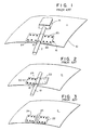
- FIGURES 1-3 illustrate prior art cable mountings used in the environments referred to above, and now will be discussed in some detail.
- Fig. 1 there is shown, generally at 10, a section of a support structure which can be an interior part of the reactor vessel, or a component part therein where a cable run 12 or test instrument 14 must be placed and securely fixed, but fixed in a way that allows for removal if desired at conclusion of the testing, the support structure having a support surface 11.
- Test instruments used can include sensors, strain gages, thermocouples, recorders, etc.
- the prior manner of effecting the mounting employs a clip 16 having a semi-circular part 18 that receives the cable, and a pair of side or wing parts, 22, 24.
- the wing parts are tack welded as at 20 to the support surface 11 to fix the cable and instrument thereon.
- one manner of doing so involves inserting a sharp tool under a corner of one of the wings to pry up a portion with which a pliers or other pulling tool can be engaged. Pulling force is then applied to that wing to break the tack welds and free up the wing. The thus far removed clip is depicted in FIGURE 2. The pulling force is thereafter continued with the pliers to pull off the other wing from the support surface.
- FIGURE 3 An alternative practice for removing the cable is to employ the expedient depicted in FIGURE 3. Since some of the cables involved can be heavily shielded types or even in some instances, conduit rather than a cable, pulling on the cable or conduit with the requisite force, simply pulls it through the semi-circular part 18, rending or shearing this clip structure as shown at 25. That procedure has the disadvantages that the clip residue parts may still be required to be removed, and a part of the residue may be broken off from a parent part and its recovery in a large reactor vessel, problematical. In some case, this removal mode also could damage the cable.
- the clip 16 serves adequate cable mounting function, it has the drawback enumerated above associated with removal. Because of such difficulties, the clip design in some cases, deters removal from the support surface as such. This choice is preferably avoided in a reactor, and particularly where a restraint clip and mounting as provided by the invention is available since same are designed to facilitate removal. Further elaboration on these is given next.
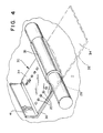
- restraint clip 30 is made from a single, elongated, widened metal strip 32, the strip in most use applications having a thickness of about 0.020 to about 0.030 inch, such thickness being one as allows ready shaping of same to the necessary clip configuration, but also provides sufficiency of structure integrity thereto to withstand the rigors presented by the use involved.
- the strip has opposite strip end sections or parts as shown at 34, 36, and a central or medial lengh part as at 28.
- the medial lengh part and strip end part 34 are shown in their shaped positions, with the pre-formed disposition of strip end part 34 shown in long and short dashed lines.
- the medial lengh part is wound around the cable as shown to form a loop part 38 of the clip which closely encircles the cable, with the strip end parts 34, 36 extending from opposite ends of the loop part, the strip end part 34 having been folded over the cable 12 to a disposition wherein it juxtaposes with strip part 36 and extends codirectionally with that part, preferably in substantial superpositioning therewith, although as will be noted later, strip part 34 may have a somewhat lesser overall lengh than strip part 36.
- the respective strip parts 34, 36 it will be seen, constitute respective anchor plates integral with the loop part.
- Loop part 38 can be formed to tightly embrace the cable 12 holding it under a constraint that insures no longitudinal displacement of the cable relative thereto when the cable and an instrument connected thereto in close proximity to the restraint clip are exposed to the pressurized fluid flow in the reactor. Further, the tight holding of the cable insures that with clip removal from a fixed position thereof, the cable and instrument are removed unitarily with the clip.
- the clip is securely but removably connected to support surface 11 by disposing the underface of anchor plate 36 in contact with support surface 11, and then with suitable electrode elements of a spot welding meams oriented to effect such purpose, passing a high current electric flow through the anchor plates and the support surface at various plural and discrete locations to cause spot welding together of the anchor plates to each other and of anchor plate 36 to the support surface.
- the loop part 38 of clip 30 is offset relative to the codirectional dispositioning of the generally flat anchor plates, and this results in the loop part and cable held therewith when the clip is mounted on the support surface, extending spaced some distance from that surface so that a space 40 (FIGURE 5) is provided behind the loop part for reception of a removal tool as will be detailed below.
- FIGURE 5 illustrates, inter alia, the feature that the anchor plates 34, 36, can be formed such that each includes a respective portion 34a, 36a, proximal the loop part, which said portions are skewed or angled relative to the plate portions 34b, 36b, which are distal or remote from the loop part.
- the loop part will be further spaced from the support surface enhancing the space available for accessing a removal tool behind the loop part.
- Plate portions 34a, 34b, 36a and 36b are in the depicted embodiment planar, although they, and particularly the distal plate portions, could have contours differently configured and in correspondence to the shape of the support surface to which anchor plate 36 is attached.
- the anchor plates in the FIGURE 4 clip embodiment are also generally flat planar since the clip of that FIGURE is intended for mounting on a flat support surface 11.
- Removal of a clip 30 from its fixed attachment to a support surface will described with reference to FIGURES 5 and 6. Removal of the clip requires exertion of a pulling force on the clip structure sufficient to break the weldment holding anchor plate 36 to support surface 11. Preferably, this will be provided in the form of a prying force directed against the loop part from behind such part and with a tool inserted between the loop part and the support surface, the support surface serving as an anchorage against which the tool can be manipulated.
- the anchorage plate 36 can be made somewhat longer than anchor plate 34 so that a tip end lengh segment of anchor plate 36 can be bent at an angle, e.g., orthogonally or at a lesser degree less than that measure, to the main part of such plate and in the direction of and extending for some distance beyond anchor plate 34 so that such bent segment can serve as a gripping tab 41 which can be gripped with a pliers or similar tool to pull the clip loose from the support surface.
- Tool 50 generally resembles a pliers in that it has a pair of pivoted together jaws 52, 54, jaw 52 being primarily a gripping member, and jaw 54, primarily a prying or force applying component for applying pulling force to the clip loop part from the rear side thereof and to the underside of anchor plate 36 when access to same is achieved in course of operation of the tool.
- the jaws are adapted in usual manner to pivot in opposite directions, i.e., pivoting of each in first directions, closes the jaws.
- Tool jaw 52 as seen in FIGURE 6 has a sawtooth or serrated innerface 56 engagable with the clip at the outer surface of the clip generally in the region of juncture of the loop part and anchor plate 34, and when the jaw is pivoted in counterclockwise direction to cause such engagement.
- This gripping of the clip with jaw 52 and maintenance of the force effecting same works in cooperation with the clockwise pivoting force applied to jaw 54 to enable the user to insert jaw 54 under the loop part, and then to advance progressively more and more under the anchor plate 36 to apply upwardly directed force against the anchor plate 36.
- jaw 54 is specially configured.
- This special configuration includes the long sweeping concave inner jaw face shape 58, and the long sweeping convex outer jaw face shape 60, these faces having different radii of curvature as is evident and designed to provide face intersection in the sharp tip end juncture depicted.
Landscapes
- Engineering & Computer Science (AREA)
- General Engineering & Computer Science (AREA)
- Physics & Mathematics (AREA)
- Plasma & Fusion (AREA)
- High Energy & Nuclear Physics (AREA)
- Mechanical Engineering (AREA)
- Supports For Pipes And Cables (AREA)
- Insertion, Bundling And Securing Of Wires For Electric Apparatuses (AREA)
- Installation Of Indoor Wiring (AREA)
Applications Claiming Priority (2)
| Application Number | Priority Date | Filing Date | Title |
|---|---|---|---|
| US07/611,607 US5118916A (en) | 1990-11-13 | 1990-11-13 | Cable mounting and removal in fluid flow environment |
| US611607 | 1990-11-13 |
Publications (1)
| Publication Number | Publication Date |
|---|---|
| EP0486228A1 true EP0486228A1 (en) | 1992-05-20 |
Family
ID=24449701
Family Applications (1)
| Application Number | Title | Priority Date | Filing Date |
|---|---|---|---|
| EP91310346A Withdrawn EP0486228A1 (en) | 1990-11-13 | 1991-11-08 | Cable mounting and removal in fluid flow environment |
Country Status (4)
| Country | Link |
|---|---|
| US (1) | US5118916A (enExample) |
| EP (1) | EP0486228A1 (enExample) |
| JP (1) | JPH04290688A (enExample) |
| TW (1) | TW220013B (enExample) |
Cited By (1)
| Publication number | Priority date | Publication date | Assignee | Title |
|---|---|---|---|---|
| CN120728467A (zh) * | 2025-08-21 | 2025-09-30 | 山东泰莱电气股份有限公司 | 一种海上光伏电站数据接入装置 |
Families Citing this family (6)
| Publication number | Priority date | Publication date | Assignee | Title |
|---|---|---|---|---|
| US5301907A (en) * | 1992-08-03 | 1994-04-12 | Julian Electric Inc. | Cable clamp |
| US5442665A (en) * | 1994-04-13 | 1995-08-15 | General Electric Company | Strain gauge instrumentation device for in-core monitor housings |
| DE19521915A1 (de) * | 1995-06-09 | 1996-12-12 | Mannesmann Ag | Vorrichtung zur Abdichtung zwischen beweglichen Anlagenteilen |
| EP2022581B1 (en) * | 2006-05-19 | 2014-10-08 | Krosakiharima Corporation | Upper nozzle-integrated plate and method of separating them |
| US8816242B2 (en) * | 2010-03-31 | 2014-08-26 | Advanced Neuromodulation Systems, Inc. | Method of fabricating implantable pulse generator using wire connections to feedthrough structures and implantable pulse generators |
| DE102013111219B4 (de) * | 2013-10-10 | 2024-04-18 | Coroplast Fritz Müller Gmbh & Co. Kg | "Umhüllungsmittel für ein langgestrecktes Gut und dessen Verwendung" |
Citations (2)
| Publication number | Priority date | Publication date | Assignee | Title |
|---|---|---|---|---|
| US2161860A (en) * | 1936-07-28 | 1939-06-13 | Telefunken Gmbh | Means to secure electric lines to a support |
| US2814860A (en) * | 1957-01-07 | 1957-12-03 | Sweeney Mfg Co B K | Tools for applying line clamps |
Family Cites Families (14)
| Publication number | Priority date | Publication date | Assignee | Title |
|---|---|---|---|---|
| US2423627A (en) * | 1944-03-15 | 1947-07-08 | Tinnerman Products Inc | Electrical conduit clamp |
| US2790614A (en) * | 1954-03-29 | 1957-04-30 | Preferred Engineering And Res | Support clip for a pipe |
| US3105139A (en) * | 1958-08-14 | 1963-09-24 | Microdot Inc | Strain gages and installation of the same |
| US3152784A (en) * | 1962-03-28 | 1964-10-13 | Lloyd A Robinson | Pipe support |
| US3173639A (en) * | 1962-10-12 | 1965-03-16 | Newport News S & D Co | Cable holder and method of manufacture and installation thereof |
| US3523173A (en) * | 1967-08-17 | 1970-08-04 | Sprague Electric Co | Insulated lead connection |
| US3519778A (en) * | 1968-01-19 | 1970-07-07 | Gen Electric | Method and apparatus for joining electrical conductors |
| DE2259172A1 (de) * | 1972-12-02 | 1974-06-20 | Rasmussen Gmbh | Schelle zum befestigen oder verbinden von bauteilen, wie rohre, schlaeuche, kabel, behaelter u. dgl |
| JPS5149498U (enExample) * | 1974-10-12 | 1976-04-14 | ||
| GB1560552A (en) * | 1976-01-28 | 1980-02-06 | Petit J A L | Cable clips |
| JPS5335760U (enExample) * | 1976-09-02 | 1978-03-29 | ||
| US4878639A (en) * | 1987-11-27 | 1989-11-07 | Westinghouse Electric Corp. | Mounting bracket for a conductor of electrical apparatus |
| JPH02217177A (ja) * | 1989-02-17 | 1990-08-29 | Kohan Kogyo Kk | 結束用帯金の多点溶接接合法 |
| US4971272A (en) * | 1989-06-29 | 1990-11-20 | United Technologies Corporation | Structure for positioning a conduit |
-
1990
- 1990-11-13 US US07/611,607 patent/US5118916A/en not_active Expired - Fee Related
-
1991
- 1991-07-03 TW TW080105166A patent/TW220013B/zh active
- 1991-11-07 JP JP3318611A patent/JPH04290688A/ja active Pending
- 1991-11-08 EP EP91310346A patent/EP0486228A1/en not_active Withdrawn
Patent Citations (2)
| Publication number | Priority date | Publication date | Assignee | Title |
|---|---|---|---|---|
| US2161860A (en) * | 1936-07-28 | 1939-06-13 | Telefunken Gmbh | Means to secure electric lines to a support |
| US2814860A (en) * | 1957-01-07 | 1957-12-03 | Sweeney Mfg Co B K | Tools for applying line clamps |
Cited By (1)
| Publication number | Priority date | Publication date | Assignee | Title |
|---|---|---|---|---|
| CN120728467A (zh) * | 2025-08-21 | 2025-09-30 | 山东泰莱电气股份有限公司 | 一种海上光伏电站数据接入装置 |
Also Published As
| Publication number | Publication date |
|---|---|
| US5118916A (en) | 1992-06-02 |
| TW220013B (enExample) | 1994-02-01 |
| JPH04290688A (ja) | 1992-10-15 |
Similar Documents
| Publication | Publication Date | Title |
|---|---|---|
| US5118916A (en) | Cable mounting and removal in fluid flow environment | |
| KR101975255B1 (ko) | 케이블 보유 장치 | |
| JP6602956B2 (ja) | 止まり穴マウント | |
| US3473768A (en) | Wire bundle clamp | |
| KR100293022B1 (ko) | 케이블고정기 | |
| US4795116A (en) | Fastener for cable strap | |
| EP4173976A2 (en) | Severing a cable tie with a rounded cut | |
| US20020147452A1 (en) | Fracture fixation device in which a fixation pin is axially restrained | |
| US4477948A (en) | Dead-end messenger wire holder | |
| JP2003102122A (ja) | 定着した係止装置を備える低挿入力ケーブルタイ | |
| US4906032A (en) | Tail pipe coupling device | |
| JPH0124120B2 (enExample) | ||
| JP2009544514A (ja) | 前部座席乗員用エアバッグ・モジュールのハウジング内にて保持枠に取り付けられたエアバッグ固定用ラッチ装置 | |
| JPH0755062A (ja) | 保持装置 | |
| EP3067994A1 (en) | Connector plug for a housing | |
| EP3706272A1 (en) | Bracket for cable management | |
| US3958379A (en) | Appliance for linear bodies | |
| WO1985004151A1 (en) | Buckle fastener and method of application | |
| US7570045B2 (en) | Attachment device and method for fastening electrical cable monitoring instruments to electrical cables | |
| US4069738A (en) | Insulation retainer and attachment method therefor | |
| US5443344A (en) | Method and apparatus for attaching two members together from one side thereof | |
| US4677712A (en) | Hose clamp with tightener | |
| EP2106246B1 (en) | Safety attachment for orthodontic wires and pliers to apply attachment | |
| JPH07135729A (ja) | ケーブル把持具 | |
| JPS591910Y2 (ja) | 係留索の分離装置 |
Legal Events
| Date | Code | Title | Description |
|---|---|---|---|
| PUAI | Public reference made under article 153(3) epc to a published international application that has entered the european phase |
Free format text: ORIGINAL CODE: 0009012 |
|
| AK | Designated contracting states |
Kind code of ref document: A1 Designated state(s): CH DE ES IT LI NL SE |
|
| STAA | Information on the status of an ep patent application or granted ep patent |
Free format text: STATUS: THE APPLICATION IS DEEMED TO BE WITHDRAWN |
|
| 18D | Application deemed to be withdrawn |
Effective date: 19930221 |