EP0486151A1 - Fördereinrichtung - Google Patents
Fördereinrichtung Download PDFInfo
- Publication number
- EP0486151A1 EP0486151A1 EP91309155A EP91309155A EP0486151A1 EP 0486151 A1 EP0486151 A1 EP 0486151A1 EP 91309155 A EP91309155 A EP 91309155A EP 91309155 A EP91309155 A EP 91309155A EP 0486151 A1 EP0486151 A1 EP 0486151A1
- Authority
- EP
- European Patent Office
- Prior art keywords
- streams
- flexible element
- liquid
- conveyor apparatus
- conveyor
- Prior art date
- Legal status (The legal status is an assumption and is not a legal conclusion. Google has not performed a legal analysis and makes no representation as to the accuracy of the status listed.)
- Granted
Links
- 239000007788 liquid Substances 0.000 claims abstract description 21
- 239000000758 substrate Substances 0.000 claims 9
- 238000007599 discharging Methods 0.000 claims 2
- 239000000975 dye Substances 0.000 abstract description 19
- 239000003638 chemical reducing agent Substances 0.000 description 9
- 239000000463 material Substances 0.000 description 8
- 230000000712 assembly Effects 0.000 description 7
- 238000000429 assembly Methods 0.000 description 7
- 125000006850 spacer group Chemical group 0.000 description 7
- 230000009977 dual effect Effects 0.000 description 6
- 238000004043 dyeing Methods 0.000 description 4
- 239000000835 fiber Substances 0.000 description 3
- 238000000034 method Methods 0.000 description 3
- 230000001960 triggered effect Effects 0.000 description 3
- XAGFODPZIPBFFR-UHFFFAOYSA-N aluminium Chemical compound [Al] XAGFODPZIPBFFR-UHFFFAOYSA-N 0.000 description 2
- 229910052782 aluminium Inorganic materials 0.000 description 2
- 230000003287 optical effect Effects 0.000 description 2
- 238000000059 patterning Methods 0.000 description 2
- 241000220010 Rhode Species 0.000 description 1
- 229920006364 Rulon (plastic) Polymers 0.000 description 1
- 239000006096 absorbing agent Substances 0.000 description 1
- 239000000853 adhesive Substances 0.000 description 1
- 230000001070 adhesive effect Effects 0.000 description 1
- 239000012636 effector Substances 0.000 description 1
- 230000000694 effects Effects 0.000 description 1
- 239000004519 grease Substances 0.000 description 1
- 230000000977 initiatory effect Effects 0.000 description 1
- 230000001050 lubricating effect Effects 0.000 description 1
- 230000013011 mating Effects 0.000 description 1
- RGCLLPNLLBQHPF-HJWRWDBZSA-N phosphamidon Chemical compound CCN(CC)C(=O)C(\Cl)=C(/C)OP(=O)(OC)OC RGCLLPNLLBQHPF-HJWRWDBZSA-N 0.000 description 1
- 230000001012 protector Effects 0.000 description 1
- 230000035939 shock Effects 0.000 description 1
- 238000001228 spectrum Methods 0.000 description 1
- 239000003381 stabilizer Substances 0.000 description 1
- 239000004753 textile Substances 0.000 description 1
Images


Classifications
-
- D—TEXTILES; PAPER
- D06—TREATMENT OF TEXTILES OR THE LIKE; LAUNDERING; FLEXIBLE MATERIALS NOT OTHERWISE PROVIDED FOR
- D06B—TREATING TEXTILE MATERIALS USING LIQUIDS, GASES OR VAPOURS
- D06B11/00—Treatment of selected parts of textile materials, e.g. partial dyeing
- D06B11/0056—Treatment of selected parts of textile materials, e.g. partial dyeing of fabrics
- D06B11/0059—Treatment of selected parts of textile materials, e.g. partial dyeing of fabrics by spraying
Definitions
- This invention relates generally to conveyor assemblies and particularly to a conveyor apparatus used in the patterned application of dyestuff or other liquids to carpeting that is in preferably the form of tile.
- the present invention solves the above problem and others in a manner not disclosed in the known prior art.
- a conveyor apparatus used primarily in processing products such as applying liquids such as dyestuff by means of a patterned application of a moving stream of dyestuff, having a first planar portion and an endless flexible element adjacent said first planar portion and a second planar portion adjacent said endless flexible element, where said flexible element has a series of slats mounted thereon that precisely coordinate the processed item underneath the processing element that provides patterned application of dyestuff in order to achieve precise repeatable results.
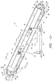
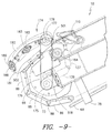
- FIG. 1 discloses an overall side elevational view of the apparatus for conveying material to which the present invention pertains.
- the apparatus is particularly adapted for transporting pile carpet material that is processed by the application of dyestuff in the form of a pattern.
- this conveyor assembly could be employed for transporting a variety of material in a wide spectrum of applications. All of the mechanical attachments in this invention may be accomplished by any of a wide variety of conventional hardware, adhesives, and so forth.
- the conveyor apparatus shown in FIG. 1 comprises a main conveyor apparatus generally indicated by numeral 1 with the conveyor mechanism proper indicated by numeral 10.
- main support frame assembly 14 that is identical on both the left side and the right hand side, which includes horizontal base I-beam supports 56 supporting upper horizontal rails 18 by means of vertical I-beam supports 9 and 16, respectively.
- ancillary vertical supports 15, 13 that also connect the horizontal base I-beam support 56 with the upper horizontal rail 18.
- Ancillary vertical support 13 has two transverse members 20 extending from the lower portion thereof on both sides to the upper horizontal rail 18.
- There is a horizontal support member 362 extending between the transverse member 20, which is on the right of ancillary vertical support 13 in FIG. 1, and vertical I-beam support 9.
- the conveyor mechanism 10 has a support system numerically delineated as numeral 11 comprising of dual horizontal support I-beams 22 forming the carriage weldment assembly with a longer rear vertical support member 24 and a comparatively shorter front vertical support member 26. There is a lateral support member 568 extending between the upper portions of vertical support members 24 and 26. Both vertical support members 24 and 26 have a leveling pad adjustment mechanism 28 that attaches to the conveyor mechanism 10.
- the leveling pad adjustment mechanism 28 comprises of a combination of hex head cap screws, hex head jam nuts and washers that are connected to an angle support bracket and is used to level the conveyor mechanism 10.
- the conveyor mechanism support system 11 and the main support frame assembly 14 are interconnected by means of a rail system indicated generally at numeral 30.
- Rail system 30 includes carriage I-beam tracks 99 located on the left and right hand side of the main conveyor apparatus 1 and running longitudinally along its length and attached to the vertical I-beam supports 9 and 16 by means of support brackets 98. Cylindrical rails 31 are attached to each of the carriage I-beam tracks 99 by means of rail support spacers 34.
- the conveyor mechanism support system 11 can move along the cylindrical rails 31 by means of four Thomson ® pillow block bearings 36, which are in effect open linear bearings and available from Thomson Industries of Port Washington, New York which surround and ride the cylindrical rails 31 and that are located on each side of the main conveyor apparatus 1 with one mounted underneath and outward from horizontal support I-beam 22 and below and outward from rear vertical support member 24 and the other pillow block linear bearing 36 also mounted underneath horizontal support I-beam 22 and below and outward from front vertical support member 26, as shown in FIGS. 8 and 13.
- Four Thomson ® pillow block bearings 36 which are in effect open linear bearings and available from Thomson Industries of Port Washington, New York which surround and ride the cylindrical rails 31 and that are located on each side of the main conveyor apparatus 1 with one mounted underneath and outward from horizontal support I-beam 22 and below and outward from rear vertical support member 24 and the other pillow block linear bearing 36 also mounted underneath horizontal support I-beam 22 and below and outward from front vertical support member 26, as shown in FIGS. 8 and 13.
- the dyeing apparatus shown generally as numeral 40 is supported by a main dye applicator support frame 42.
- a main dye apparatus forwardly slanting support member 96 with a relatively longer rear dye apparatus vertical support member 97 and a relatively shorter front dye apparatus vertical support member 100 attached thereto.
- the front dye apparatus vertical support member 100 is attached to horizontal base I-beam support 56 at the base of the main conveyor apparatus 1.
- the rear dye apparatus vertical support 97 is also attached to the carriage I-beam track 99 by means of support bracket 98.
- There is a horizontal support beam 360 extending between rear dye apparatus vertical support 97 and vertical I-beam support 9.
- the dyeing apparatus 40 is disclosed in U.S. Patent No. 3,393,411, U.S. Patent No. 3,894,413, U.S. Patent No. 3,942,343, U.S. Patent No. 4,019,352, U.S. Patent No. 4,202,189, U.S. Patent No. 4,033,154, U.S. Patent No. 4,034,584, U.S. Patent 4,116,626, U.S. Patent No. 4,309,881, U.S. Patent No. 4,434,632, and U.S. Patent No. 4,584,854.
- the subject matter disclosed in each of the eleven U.S. Patents identified hereinabove is hereby incorporated by reference into the instant disclosure.
- a plurality of dye applicator members, or gun bar assemblies 44 Positioned above and spaced along the length of main conveyor mechanism 10 are a plurality of dye applicator members, or gun bar assemblies 44, which extend in parallel, spaced relation across the width of the conveyor mechanism 10.
- the gun bar assemblies 44 are each provided with a different color dye in order to apply a colored pattern to the carpet.
- the length of the conveyor may vary depending on the number of gun bar assemblies used.
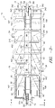
- the main conveying means of this invention is an endless loop of conveyor plates 86 that are connected by linking pin joints 88 that rotate in a hinge-like manner to provide flexibility.
- the main portion of the conveyor mechanism 10 has an upper layer 434, intermediate layer 132 and lower layer 135.
- Each opposing longitudinal end of the conveyor mechanism 10 has an upper and lower pin wheel 72 and 73 respectively.
- Each pin wheel 72, 73 has seven sides and is mounted on a respective shaft 70, 71 that rotates within a respective pillow block linear bearing 60, 61.
- Pillow block linear bearing 60 is mounted on a mounting bracket assembly 74, while pillow block linear bearing 61 is mounted directly to the front of conveyor mechanism 10.
- the upper pin wheel 72 is protected from access by a stand-off load station guard 62.
- the pin wheels 72, 72 guide and rotate the conveyor plates 86 that travel the longitudinal length through the lateral center of the conveyor mechanism 10.
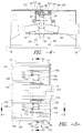
- FIGS. 3, 4 and 15 there are panels 90 on each side of the moving conveyor plates 86.
- These panels 90 are made from a product manufactured by E. I. du Pont de Nemours & Company of Wilmington, Delaware called CORIAN® that is traditionally used as a material for countertops and can be categorized as a type of plastic. However, a wide variety of materials may be used as a conveyor surface as well as a surface may be used underneath such as a quarter of one inch of aluminum.
- These panels are attached to the top of the conveyor mechanism 10 by means of bolts 92 or other attachment means.
- the moving conveyor plates 86 have linear pillow block linear bearings 105, 106 mounted underneath the moving conveyor plates 86 that ride on and enclose cylindrical shafts 103, 104, as shown in FIG. 4.
- the longitudinal shafts 103, 104 are mounted on support rails 107, 108 that extends longitudinally with said shafts 103, 104.
- the conveyor plates 86 have numerous tapped holes with inserts 401 upon which can be attached a slat 402 or plurality thereof that extends across the width of the conveyor mechanism 10 and can accommodate a variety of product of various lengths, i.e., carpet tile.
- the upper and lower pin wheels 72 and 73 respectively, have two parallel plates 53 and 57 that are separated by cylindrical spacers 58 attached by an associated screw and nut. There is an interconnection member 351 between adjacent spacers 58, as shown in FIG. 4. There is a pin wheel support bar 374, 375 located at each end of the conveyor mechanism 10 located at the rear and front of the conveyor mechanism respectively. There is also a left hand mounting bracket 380 and a right hand mounting bracket 381 for the upper pin wheel 72. As shown in FIG. 4, there is both a left hand drip shield 390 and right hand drip shield 391 positioned underneath the longitudinal shafts 103 and 104 respectively. Located at the rear of the conveyor mechanism 10 is a slat protector 342 and mounting angle 343.
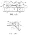
- the mechanical lifter 110 is a means to flip objects from out the end of the bottom end of the conveyor mechanism 10.
- the lifter 110 is connected to a shaft 114 by means of an attachment mechanism 112.
- the attachment mechanism 112 is called a Trantorque ® unit that is manufactured by Fenner Manheim of Manheim, Pennsylvania and is connected to the shaft 114.
- the attachment mechanism 112 will rotate in place around the shaft 114 if opposed by more than 1800 inch/pounds of torque. This will protect the lifters 110 if they come into contact with any slats 402 mounted to the conveyor plates 86.
- the shaft 114 is held in a fixed position by a combination of a two piece clamp collar 121 and thrust bearing 126.
- the shaft 114 is rotatively mounted in a sleeve bearing 120 having the trademark Rulon ® and is manufactured by Dixon Industries Corporation of Bristol, Rhode Island that is connected to a mounting bracket 122 that is attached to the conveyor mechanism 10 by a series of four bolts 426 at an intermediate level 132.
- the conveyor mechanism 10 has a lower layer 135 that connects to the intermediate layer 132 by means of vertical support members 133.
- the upper layer 434 comprising of panels 90 on top of a one-quarter inch of aluminum as shown in FIG. 7, is not shown in FIGS. 5 and 6.
- There is a flat cover plate 130 that conceals the middle of shaft 114.
- a fiber optic sensor assembly generally indicated as numeral 532 comprising a fiber optic sensor 145 utilized to detect the presence of an object, such as a carpet tile, on the end of the conveyor 10 as shown in FIGS. 5 and 15.
- the sensor 145 is connected to a mounting plate 146 by means of a hex head cap screw and washers that is then attached to a spacer 149 that is attached to the conveyor mechanism 10 by means of a socket head cap screw.
- the mechanical lifter 110 is actuated by means of a cylinder 137 with preferably a one and one-half inch bore and a two inch stroke.
- the cylinder 137 is pivotally attached to the end of the conveyor mechanism 10 by means of a mounting bracket 139 and pivot pin 141.
- the lifter 110 is attached to the cylinder 137 by means of a clevis 143 using a hexagonal jam nut.
- the conveyor assembly base generally indicated as numeral 155, as shown in FIG. 8, has dual longitudinal support members 56 between two end members 158 and 159.
- the conveyor mechanism support system 11 with interacting cross beams 161 allows the conveyor mechanism 10 to be able to move away from and underneath the gun bar assemblies 44. This movement is actuated by means of a motor 162, also shown in FIG. 1, such as a one horsepower, 1750 r.p.m., 240 volt d.c. motor operating in conjunction with a c-face, triple reduction, parallel reducer at a 129:1 ratio, which has a carriage drive pulley 163 that winds and unwinds a cable 164 that is stretched between two cable clips 165 and 166.
- a motor 162 also shown in FIG. 1, such as a one horsepower, 1750 r.p.m., 240 volt d.c. motor operating in conjunction with a c-face, triple reduction, parallel reducer at a 129:1 ratio, which has a carriage drive pulley
- air cylinder 152 attached to cable clip 165 that is fastened to the longitudinal support member 56 by means of bracket 153.
- shock absorbers 260 and 261 mounted on L-shaped mounting brackets and located at each end of relative travel of the conveyor support system 11.
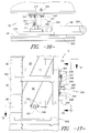
- the take-off conveyor is shown generally by numeral 174, as well as in FIGS. 1 and 15, is mounted to the end of the conveyor mechanism 10 by mating L-shaped mounting brackets 502. Tiles are sensed by fiber optic sensor 145, as shown in FIGS. 5 and 10, and then placed on the take-off conveyor 174 by mechanical lifter 110 in conjunction with a triangular tile transfer bar 501, with the lifter 110 being actuated by a cylinder 137 that is fixedly attached to the end of the conveyor by mounting bracket 139.
- the pin wheels 72, 73 guide the endless loop of conveyor plates 86 with linking pin joints 88 around the conveyor mechanism 10.
- the take-off conveyor 174 is powered by a pulley 175 driven by a one-fourth horsepower, 3-125 r.p.m., 90 volt DC motor (not shown) that is mounted by angle bracket 518 to the front end of the conveyor mechanism.
- the pulley 175 drives another pulley 177 by means of a continuous belt 176, as shown in FIGS. 9 and 10.
- Pulley 177 is connected to drive shaft 178 that traverses the width of the take-off conveyor 174 and is held in position by flange bearings 179 and 180 that are held in position by side plates 181 and 182 respectively.
- an idler shaft 183 that is rotatable held in position by flange bearings 185 and 186 respectively. Positioned on each side of the idler shaft 183 are positioning rods 187 that extends between side plates 181 and 182 and is connected only by bolts and not bearings.
- a belt tensioning shaft 188 held in position by bearings 189 and 190 that are also mounted on side plates 181 and 182 respectively.
- Conveyor mechanism support system 11 comprises vertical support members 24 and 26 mounted on the horizontal support I-beam 22 that is connected to Thomson® pillow block linear bearings 36 that ride on the cylindrical rail 31 that is attached to the rail support spacers 34 that are connected to the carriage I-beam track 99.
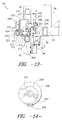
- a main component of the locking assembly 461 is a helical gear reducer 203 operated by a handwheel 209.
- the helical gear reducer 203 controls a locking cam 205 by encircling a bearing 207 that is attached to a hydraulic lubricating fitting and associated bar 206 by means of hex jam nuts 278. This encirclement of the bearing 207 is what locks the conveyor mechanism support system 11 in place. As shown in FIG. 14, the locking cam 205 has an elevated rim 208 around approximately three-quarters of its circumference.
- the locking cam is attached to the helical gear reducer by a socket set cup point 220. There is a cam lock switch target 234 attached to the side of the locking cam 205 by two socket head cap screws.
- the helical gear reducer 203 is attached to the main cover mounting angle 210 that has Thomson ® pillow block linear bearings 211 attached to the underside thereof, which ride on dual index shafts 222 held in position on each side of their three (3) inch length by support blocks 212 that are attached to an index block 213.
- the index block 213 is attached to a L-shaped index base 214 that is connected to a lateral index support member 283 that connects vertical I-beam support 16 and ancillary vertical support 15.
- There is an outer index block 225 having fifteen (15) separate locations for varying heights of carpet or other processed articles that connect to holes in inner index block 226 by means of an expanding pin 223 that holds the locking assembly 461 in a fixed location with relation to the index shafts 222.
- the carriage sensor switch 217 is connected to the bar 206 and comprises a spacer and socket head cap screw.
- Sensor 270 is attached to a mounting bracket 267 that is attached to a mounting plate 265 that connects to a mounting post 266 that is connected to the lateral index support member 283.
- the signal from the sensor 270 goes to the control system that regulates by slowing down the motor 162 of FIG. 8.
- Closer to the helical gear reducer 203 is another sensor 271 which is also triggered by the carriage sensor switch target 217, but this time the control system stops the rotation of motor 162.
- cam unlock sensor 272 that is located on the right of the locking cam 205 in FIG. 11 and looks toward the cam 205.
- cam unlock switch target 291 that is attached to the locking cam 205 that triggers the sensor 272.
- the cam unlock sensor 272 has a mounting bracket 253 attached to mounting angle 210.
- the mounting bracket 254 for sensor 271 is attached to mounting bracket 253.
- cam lock sensor 273 that is located on the left of the locking cam 205 and looks toward the cam and is triggered by the cam lock switch target 234.
- Cam lock sensor 273 is mounted on mounting bracket 286.
- FIGS. 1, 15 and 16 that disclose the transport link return guidance assembly 66, in which there are two dual wheels 230 on the underside of the conveyor mechanism 10 to hold the conveyor plates 86 in horizontal alignment with respect to the longitudinal axis of the conveyor mechanism 10. Both wheels 230 are mounted on a wheel guide base plate 307. Each wheel 230 has a bearing assembly 231 with a shaft 309 within a bearing housing 310 and attached by means of a bolt 311 to the base plate 307.
- the guide wheel base plate 307 is attached to the conveyor mechanism 10 by means of bolt and nut combination 312.
- FIG. 16 also reveals a conveyor plate 86 with associated slat 402 being aligned by a wheel 230.
- FIGS. 3, 15, 17, 18, 19, and 25 there are a pair of effector switch sensors 240 mounted underneath the conveyor mechanism 10 and held to the underside of the conveyor mechanism 10 by means of a clamp and associated cap assembly 341 and held into position by a series of screws and washers 388 and is directed upward on each side of the conveyor to detect the presence of carpet tiles or any other processed article and thereby feed this information into the control system of the processing equipment.
- the location of sensors the 240 is toward the rear of the conveyor mechanism 10, as shown in FIGS. 3 and 15.
- There is a start print sensor assembly is generally indicated at numeral 250 that actuates the control system in order to enable the computerized dyeing process.
- This start print sensor assembly 250 utilizes a high speed reflective sensor 382 and has a surrounding guard 299 to protect it and is mounted to the conveyor mechanism 10 by means of a base and clamp combination 345 that is attached to a mounting bracket 298 by means of conventional hardware 344 such as a shoulder bolts and/or cap screws.
- the mounting bracket 343 has oval holes through which shoulder bolts and cap screws connect to the conveyor mechanism 10.
- the mounting bracket 343 can be positioned by means of an adjustment rod 347 that is threadedly connected to an adjustment block 346.
- the adjustment block 346 is bolted to the side of the conveyor mechanism 10.
- the adjustment rod 347 is connected to extension of the mounting bracket by means of a set screw 348. There are nuts on each side of the adjustment rod 347 that alters the position of the mounting bracket 343.
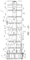
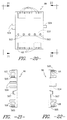
- the conveyor plates 86 travel along a defined path along the center of the longitudinal path of the conveyor mechanism 10. As shown in FIGS. 20, 21, and 22, the conveyor plate is shown in detail with numerous tapped holes with assorted inserts 401 for the attachment of slats 402 at various positions depending on the size of carpet tile being processed.
- There is also a retainer 505 that is held in place by a hex head screw and washer or equivalents thereof.
- There are linking and protruding interconnection portions 504 that are held in place by cup point socket set screws and serve to interconnect the conveyor plates 86 by linking pin joints 88.
- the rack gear 507 is an integral part of the drive means for the conveyor mechanism 10.
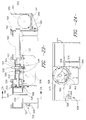
- the conveyor plates 86 are powered by a drive gear 520 that is located toward the rear of the conveyor mechanism 10, as shown in FIG. 2 and interconnects with the rack gear 507 to power the conveyor mechanism 10.
- the drive gear 520 is fixedly attached to a drive shaft 522 by means of a retaining ring 521.
- the housings 524 are bolted 534 or equivalent means thereof to the intermediate level 132 of the conveyor.
- the bearings 523 are lubricated by a series of conduits 526 which run from the bearing housings 524 to a grease fitting generally indicated as numeral 525 including a block 527 and male connectors 528.
- the drive shaft 522 is also connected to an optical incremental encoder 529 with a rawhide seal 530 and encoder seal 531, from left to right as shown on FIG. 23.
- the encoder 529 also has a mounting bushing 561 as well as cover 533 and torque arm 535.
- the opposite side of shaft 522 is connected to a gear reducer 543 that has a 60:1 ratio with a guard bracket 542 and a lower mounting bracket 540 that is attached by means of bolts 541 to the conveyor mechanism 10 and the gear reducer 543.
- the optical encoder 529 has a mounting base 570 as well as an o-ring 560 to mount thereon.
- the encoder 529 has a spring stud 562 with a spring 563 attached thereto that connects to and controls the torque arm 595.
Landscapes
- Engineering & Computer Science (AREA)
- Chemical & Material Sciences (AREA)
- Materials Engineering (AREA)
- Textile Engineering (AREA)
- Chain Conveyers (AREA)
- Attitude Control For Articles On Conveyors (AREA)
- Treatment Of Fiber Materials (AREA)
- Liquid Crystal (AREA)
- Formation And Processing Of Food Products (AREA)
- Screw Conveyors (AREA)
- Manufacturing And Processing Devices For Dough (AREA)
- Discharge Of Articles From Conveyors (AREA)
- Spray Control Apparatus (AREA)
- Fish Paste Products (AREA)
- Apparatuses For Bulk Treatment Of Fruits And Vegetables And Apparatuses For Preparing Feeds (AREA)
- Application Of Or Painting With Fluid Materials (AREA)
- Coating Apparatus (AREA)
Applications Claiming Priority (2)
| Application Number | Priority Date | Filing Date | Title |
|---|---|---|---|
| US613341 | 1984-05-23 | ||
| US61334190A | 1990-11-14 | 1990-11-14 |
Publications (2)
| Publication Number | Publication Date |
|---|---|
| EP0486151A1 true EP0486151A1 (de) | 1992-05-20 |
| EP0486151B1 EP0486151B1 (de) | 1996-04-17 |
Family
ID=24456940
Family Applications (1)
| Application Number | Title | Priority Date | Filing Date |
|---|---|---|---|
| EP91309155A Expired - Lifetime EP0486151B1 (de) | 1990-11-14 | 1991-10-07 | Fördereinrichtung |
Country Status (7)
| Country | Link |
|---|---|
| EP (1) | EP0486151B1 (de) |
| JP (1) | JP3461515B2 (de) |
| AT (1) | ATE136955T1 (de) |
| AU (1) | AU646901B2 (de) |
| CA (1) | CA2052519C (de) |
| DE (1) | DE69118820T2 (de) |
| DK (1) | DK0486151T3 (de) |
Cited By (2)
| Publication number | Priority date | Publication date | Assignee | Title |
|---|---|---|---|---|
| CN109434333A (zh) * | 2018-12-05 | 2019-03-08 | 安徽工程大学 | 一种半挂车底盘焊接用的上料夹紧装置 |
| CN117228223A (zh) * | 2023-09-19 | 2023-12-15 | 中煤科工集团南京设计研究院有限公司 | 一种矿用模块化给煤机 |
Families Citing this family (4)
| Publication number | Priority date | Publication date | Assignee | Title |
|---|---|---|---|---|
| US7588372B2 (en) | 2006-04-13 | 2009-09-15 | Bishop-Wisecarver Corporation | Guide wheel having a bearing for food and beverage applications |
| CN109502296B (zh) * | 2019-01-07 | 2024-07-30 | 昆山金蚂蚁精密机械有限公司 | Ic芯片测试机的翻转上料装置 |
| CN112007800B (zh) * | 2020-07-28 | 2021-10-26 | 江苏衡云智能科技有限公司 | 一种用于地磅底座烘干的烘炉及使用方法 |
| CN116853812B (zh) * | 2023-09-04 | 2023-12-26 | 山西星心半导体科技有限公司 | 一种用于pcb板制造的分类输送装置 |
Citations (2)
| Publication number | Priority date | Publication date | Assignee | Title |
|---|---|---|---|---|
| FR2256981A1 (de) * | 1974-01-03 | 1975-08-01 | Deering Milliken Res Corp | |
| FR2256982A1 (de) * | 1974-01-03 | 1975-08-01 | Deering Milliken Res Corp |
Family Cites Families (3)
| Publication number | Priority date | Publication date | Assignee | Title |
|---|---|---|---|---|
| US3073430A (en) * | 1960-07-25 | 1963-01-15 | Richard E Quinn | Apparatus for stripping hides from conveyors |
| US3985006A (en) * | 1974-01-03 | 1976-10-12 | Deering Milliken Research Corporation | Dyeing and printing of materials |
| US4034584A (en) * | 1974-07-30 | 1977-07-12 | Milliken Research Corporation | Dyeing and printing of materials |
-
1991
- 1991-09-30 CA CA002052519A patent/CA2052519C/en not_active Expired - Fee Related
- 1991-10-07 DK DK91309155.9T patent/DK0486151T3/da active
- 1991-10-07 DE DE69118820T patent/DE69118820T2/de not_active Expired - Fee Related
- 1991-10-07 AT AT91309155T patent/ATE136955T1/de not_active IP Right Cessation
- 1991-10-07 EP EP91309155A patent/EP0486151B1/de not_active Expired - Lifetime
- 1991-10-31 JP JP31382991A patent/JP3461515B2/ja not_active Expired - Fee Related
- 1991-11-07 AU AU87089/91A patent/AU646901B2/en not_active Expired
Patent Citations (2)
| Publication number | Priority date | Publication date | Assignee | Title |
|---|---|---|---|---|
| FR2256981A1 (de) * | 1974-01-03 | 1975-08-01 | Deering Milliken Res Corp | |
| FR2256982A1 (de) * | 1974-01-03 | 1975-08-01 | Deering Milliken Res Corp |
Cited By (3)
| Publication number | Priority date | Publication date | Assignee | Title |
|---|---|---|---|---|
| CN109434333A (zh) * | 2018-12-05 | 2019-03-08 | 安徽工程大学 | 一种半挂车底盘焊接用的上料夹紧装置 |
| CN109434333B (zh) * | 2018-12-05 | 2023-09-22 | 安徽工程大学 | 一种半挂车底盘焊接用的上料夹紧装置 |
| CN117228223A (zh) * | 2023-09-19 | 2023-12-15 | 中煤科工集团南京设计研究院有限公司 | 一种矿用模块化给煤机 |
Also Published As
| Publication number | Publication date |
|---|---|
| JP3461515B2 (ja) | 2003-10-27 |
| DE69118820D1 (de) | 1996-05-23 |
| AU646901B2 (en) | 1994-03-10 |
| EP0486151B1 (de) | 1996-04-17 |
| JPH04267963A (ja) | 1992-09-24 |
| AU8708991A (en) | 1992-05-21 |
| CA2052519C (en) | 2003-10-28 |
| ATE136955T1 (de) | 1996-05-15 |
| DE69118820T2 (de) | 1996-09-05 |
| DK0486151T3 (da) | 1996-08-26 |
| CA2052519A1 (en) | 1992-05-15 |
Similar Documents
| Publication | Publication Date | Title |
|---|---|---|
| US5193363A (en) | Conveyor assembly apparatus | |
| NZ213032A (en) | Sorting plant: plurality of conveyor carriages with independent drive means | |
| US4712670A (en) | Mechanism for the transportation of objects | |
| US6648121B2 (en) | Deviating device for a conveyor | |
| DE102016125533B4 (de) | Förderanlage mit einer Fördervorrichtung | |
| DE69814684T2 (de) | Gelenkförderer | |
| US4180150A (en) | Multi-directional transfer device | |
| GB2297303A (en) | Carrier conveyor system | |
| EP0486151B1 (de) | Fördereinrichtung | |
| DE277447T1 (de) | System zur ermittlung der bewegung eines raupenfahrzeuges. | |
| CN1092374A (zh) | 容器的传运装置 | |
| GB2053824A (en) | Endless conveyors | |
| EP1045808B1 (de) | Fördereinrichtung mit einem übernahmeförderer zur übernahme von fördergutträgern von einem hängeförderer | |
| DE98401400T1 (de) | Vorrichtung zur Beabstandung und Übergabe von Produkten, die kontinuierlich mit drei Ketten arbeitet | |
| US5207314A (en) | Device for horizontally holding loading bases moving circulatively in vertical plane | |
| US4776452A (en) | Mechanism for the transportation of objects | |
| US5476191A (en) | Package dispensing apparatus | |
| EP0192617A3 (en) | Continuous-cycle painting booth, inclusive of the drying step | |
| DE19731656C1 (de) | Vorrichtung zum Überschieben von Verpackungseinheiten, insbesondere Kästen und Kartons zu Verteil- oder Aussortierzwecken | |
| KR20190014289A (ko) | 제품 그룹 포장 간격 조절장치 | |
| CA2026931A1 (en) | Spray painting system | |
| US5103968A (en) | Parallel centerline chain drive | |
| EP0886691B1 (de) | Spannmaschine für eine textile stoffbahn | |
| EP0191556B1 (de) | Sprühgerät | |
| CN211109678U (zh) | 一种行李托盘水平分流装置 |
Legal Events
| Date | Code | Title | Description |
|---|---|---|---|
| PUAI | Public reference made under article 153(3) epc to a published international application that has entered the european phase |
Free format text: ORIGINAL CODE: 0009012 |
|
| AK | Designated contracting states |
Kind code of ref document: A1 Designated state(s): AT BE CH DE DK ES FR GB GR IT LI LU NL SE |
|
| 17P | Request for examination filed |
Effective date: 19920507 |
|
| 17Q | First examination report despatched |
Effective date: 19940830 |
|
| GRAA | (expected) grant |
Free format text: ORIGINAL CODE: 0009210 |
|
| AK | Designated contracting states |
Kind code of ref document: B1 Designated state(s): AT BE CH DE DK ES FR GB GR IT LI LU NL SE |
|
| PG25 | Lapsed in a contracting state [announced via postgrant information from national office to epo] |
Ref country code: IT Free format text: LAPSE BECAUSE OF FAILURE TO SUBMIT A TRANSLATION OF THE DESCRIPTION OR TO PAY THE FEE WITHIN THE PRE;WARNING: LAPSES OF ITALIAN PATENTS WITH EFFECTIVE DATE BEFORE 2007 MAY HAVE OCCURRED AT ANY TIME BEFORE 2007. THE CORRECT EFFECTIVE DATE MAY BE DIFFERENT FROM THE ONE RECORDED.SCRIBED TIME-LIMIT Effective date: 19960417 Ref country code: AT Effective date: 19960417 Ref country code: BE Effective date: 19960417 Ref country code: FR Effective date: 19960417 Ref country code: CH Effective date: 19960417 Ref country code: NL Free format text: LAPSE BECAUSE OF FAILURE TO SUBMIT A TRANSLATION OF THE DESCRIPTION OR TO PAY THE FEE WITHIN THE PRESCRIBED TIME-LIMIT Effective date: 19960417 Ref country code: GR Free format text: LAPSE BECAUSE OF FAILURE TO SUBMIT A TRANSLATION OF THE DESCRIPTION OR TO PAY THE FEE WITHIN THE PRESCRIBED TIME-LIMIT Effective date: 19960417 Ref country code: LI Effective date: 19960417 Ref country code: ES Free format text: THE PATENT HAS BEEN ANNULLED BY A DECISION OF A NATIONAL AUTHORITY Effective date: 19960417 |
|
| REF | Corresponds to: |
Ref document number: 136955 Country of ref document: AT Date of ref document: 19960515 Kind code of ref document: T |
|
| REF | Corresponds to: |
Ref document number: 69118820 Country of ref document: DE Date of ref document: 19960523 |
|
| PG25 | Lapsed in a contracting state [announced via postgrant information from national office to epo] |
Ref country code: SE Effective date: 19960717 |
|
| GRAH | Despatch of communication of intention to grant a patent |
Free format text: ORIGINAL CODE: EPIDOS IGRA |
|
| REG | Reference to a national code |
Ref country code: DK Ref legal event code: T3 |
|
| EN | Fr: translation not filed | ||
| NLV1 | Nl: lapsed or annulled due to failure to fulfill the requirements of art. 29p and 29m of the patents act | ||
| PG25 | Lapsed in a contracting state [announced via postgrant information from national office to epo] |
Ref country code: LU Free format text: LAPSE BECAUSE OF NON-PAYMENT OF DUE FEES Effective date: 19961031 |
|
| REG | Reference to a national code |
Ref country code: CH Ref legal event code: PL |
|
| PLBE | No opposition filed within time limit |
Free format text: ORIGINAL CODE: 0009261 |
|
| STAA | Information on the status of an ep patent application or granted ep patent |
Free format text: STATUS: NO OPPOSITION FILED WITHIN TIME LIMIT |
|
| 26N | No opposition filed | ||
| REG | Reference to a national code |
Ref country code: GB Ref legal event code: 732E |
|
| REG | Reference to a national code |
Ref country code: GB Ref legal event code: IF02 |
|
| PGFP | Annual fee paid to national office [announced via postgrant information from national office to epo] |
Ref country code: DE Payment date: 20061130 Year of fee payment: 16 |
|
| PGFP | Annual fee paid to national office [announced via postgrant information from national office to epo] |
Ref country code: DK Payment date: 20071031 Year of fee payment: 17 |
|
| PG25 | Lapsed in a contracting state [announced via postgrant information from national office to epo] |
Ref country code: DE Free format text: LAPSE BECAUSE OF NON-PAYMENT OF DUE FEES Effective date: 20080501 |
|
| REG | Reference to a national code |
Ref country code: DK Ref legal event code: EBP |
|
| PG25 | Lapsed in a contracting state [announced via postgrant information from national office to epo] |
Ref country code: DK Free format text: LAPSE BECAUSE OF NON-PAYMENT OF DUE FEES Effective date: 20081031 |
|
| PGFP | Annual fee paid to national office [announced via postgrant information from national office to epo] |
Ref country code: GB Payment date: 20101025 Year of fee payment: 20 |
|
| REG | Reference to a national code |
Ref country code: GB Ref legal event code: PE20 Expiry date: 20111006 |
|
| PG25 | Lapsed in a contracting state [announced via postgrant information from national office to epo] |
Ref country code: GB Free format text: LAPSE BECAUSE OF EXPIRATION OF PROTECTION Effective date: 20111006 |