EP0485996A2 - Système flexible d'enregistrement-en-sortie d'articles et de gestion d'inventaire - Google Patents
Système flexible d'enregistrement-en-sortie d'articles et de gestion d'inventaire Download PDFInfo
- Publication number
- EP0485996A2 EP0485996A2 EP91119370A EP91119370A EP0485996A2 EP 0485996 A2 EP0485996 A2 EP 0485996A2 EP 91119370 A EP91119370 A EP 91119370A EP 91119370 A EP91119370 A EP 91119370A EP 0485996 A2 EP0485996 A2 EP 0485996A2
- Authority
- EP
- European Patent Office
- Prior art keywords
- check
- item
- bar code
- items
- related information
- Prior art date
- Legal status (The legal status is an assumption and is not a legal conclusion. Google has not performed a legal analysis and makes no representation as to the accuracy of the status listed.)
- Granted
Links
- 238000004891 communication Methods 0.000 claims description 19
- 238000012545 processing Methods 0.000 claims description 17
- 238000000034 method Methods 0.000 claims description 13
- 238000013479 data entry Methods 0.000 claims description 10
- 238000012546 transfer Methods 0.000 claims description 7
- 238000004519 manufacturing process Methods 0.000 claims 1
- 235000013339 cereals Nutrition 0.000 description 16
- 238000010586 diagram Methods 0.000 description 12
- 230000006870 function Effects 0.000 description 12
- 230000015654 memory Effects 0.000 description 9
- 230000008569 process Effects 0.000 description 7
- 230000008901 benefit Effects 0.000 description 4
- 238000005516 engineering process Methods 0.000 description 4
- 239000000976 ink Substances 0.000 description 4
- 238000007639 printing Methods 0.000 description 4
- 230000005540 biological transmission Effects 0.000 description 3
- 238000013497 data interchange Methods 0.000 description 3
- 238000007726 management method Methods 0.000 description 3
- 238000012015 optical character recognition Methods 0.000 description 3
- 230000008859 change Effects 0.000 description 2
- 230000003287 optical effect Effects 0.000 description 2
- 230000008520 organization Effects 0.000 description 2
- 230000002093 peripheral effect Effects 0.000 description 2
- 238000013519 translation Methods 0.000 description 2
- 241000321728 Tritogonia verrucosa Species 0.000 description 1
- 230000003213 activating effect Effects 0.000 description 1
- 238000013475 authorization Methods 0.000 description 1
- 235000015496 breakfast cereal Nutrition 0.000 description 1
- 235000013574 canned fruits Nutrition 0.000 description 1
- 238000007596 consolidation process Methods 0.000 description 1
- 238000001514 detection method Methods 0.000 description 1
- 230000000694 effects Effects 0.000 description 1
- 238000009408 flooring Methods 0.000 description 1
- 238000009434 installation Methods 0.000 description 1
- 230000033001 locomotion Effects 0.000 description 1
- 230000007246 mechanism Effects 0.000 description 1
- 238000004806 packaging method and process Methods 0.000 description 1
- 238000012856 packing Methods 0.000 description 1
- 238000007634 remodeling Methods 0.000 description 1
- 239000004065 semiconductor Substances 0.000 description 1
- 230000029305 taxis Effects 0.000 description 1
- 235000013311 vegetables Nutrition 0.000 description 1
- 230000000007 visual effect Effects 0.000 description 1
- 239000002699 waste material Substances 0.000 description 1
Images


Classifications
-
- G—PHYSICS
- G07—CHECKING-DEVICES
- G07G—REGISTERING THE RECEIPT OF CASH, VALUABLES, OR TOKENS
- G07G1/00—Cash registers
- G07G1/0036—Checkout procedures
- G07G1/0045—Checkout procedures with a code reader for reading of an identifying code of the article to be registered, e.g. barcode reader or radio-frequency identity [RFID] reader
-
- G—PHYSICS
- G06—COMPUTING; CALCULATING OR COUNTING
- G06K—GRAPHICAL DATA READING; PRESENTATION OF DATA; RECORD CARRIERS; HANDLING RECORD CARRIERS
- G06K7/00—Methods or arrangements for sensing record carriers, e.g. for reading patterns
- G06K7/10—Methods or arrangements for sensing record carriers, e.g. for reading patterns by electromagnetic radiation, e.g. optical sensing; by corpuscular radiation
- G06K7/14—Methods or arrangements for sensing record carriers, e.g. for reading patterns by electromagnetic radiation, e.g. optical sensing; by corpuscular radiation using light without selection of wavelength, e.g. sensing reflected white light
- G06K7/1404—Methods for optical code recognition
- G06K7/146—Methods for optical code recognition the method including quality enhancement steps
- G06K7/1486—Setting the threshold-width for bar codes to be decoded
-
- G—PHYSICS
- G07—CHECKING-DEVICES
- G07G—REGISTERING THE RECEIPT OF CASH, VALUABLES, OR TOKENS
- G07G1/00—Cash registers
- G07G1/0036—Checkout procedures
Definitions
- the present invention relates to apparatus for utilizing scanners (e.g., contact scanners or laser-beam scanners) in conjunction with optical read-only memories (e.g., "bar codes") to achieve various useful results.
- scanners e.g., contact scanners or laser-beam scanners
- optical read-only memories e.g., "bar codes
- a flexible information input system is used to speed up customer check-outs at high-volume retail establishments such as, e.g., grocery stores, large toy stores, and the like.
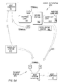
- FIG. 1 An exemplar data communications network is shown; the network is described in more detail in the commonly assigned co-pending application Serial No. 374,452, PACKET DATA COMMUNICATION NETWORK, filed June 29, 1989.
- a host processor 10 is connected by a communications link 11 to a number of base stations 12 and 13; other base stations 14 can be coupled to the host through the base stations 12 or 13 by an RF (radio frequency)link.
- Each one of the base stations 12, 13, or 14 is coupled by an RF link to one or more remote units 15 (sometimes referred to for convenience herein as "terminals” or “readers”).
- the RF link utilizes a protocol, a timing diagram of which is depicted in Figure 2 as explained in more detail in the aforementioned co-pending application.
- the remote units 15 may be connected to the host processor 10 by physical wiring, perhaps via one or more intermediary units 12, 13, or 14.
- the remote units 15 are laser-scan bar-code readers of the hand-held, battery-operated type, for example, as disclosed in U.S. Patents No. 4,387,297; 4,409,470; or 4,760,248, all commonly assigned with this application to Symbol Technologies, Inc.
- Various other types of remote terminals may be advantageously employed in a system in accordance with the invention; these remote terminals would ordinarily include data entry facilities such as a keyboard or the like, as well as a display (or printer) for indicating to a user information detected, transmitted, and/or received by the remote unit 15.
- the network may be expanded by merely changing the size of address fields and the like in the digital system.
- the terminals 15 may also be bar-code readers of the wand type, and except as may be otherwise mentioned below may be stationary rather than hand-held.
- the device may be of the optical character recognition (OCR) type as well.
- (b) Host Computer Referring to Figure 3, one typical host-computer architecture is shown.
- the host processor 10 maintains a database management system (DBMS), employing suitable database management software similar to that commercially available, to which the remote units 15 make entries or inquiries via the base stations 12, 13, and 14.
- DBMS database management system
- the host processor 10 has a CPU 20 which may be a microprocessor device of the 80386 type manufactured by Intel Corporation, for example, and the CPU accesses a memory 21 via a main bus 22 to execute instructions.
- Various I/O processors 23 are used to access peripherals such as keyboard, video display, etc., as well as disk storage 24 for the database system and other computer functions.
- a communications adapter 25 couples the CPU 20 via the main bus 22 to the link 11.
- This communications link 11 may be of the serial type such as RS-232, or alternatively the link 11 may use one of the available local area network (LAN) type of protocols.
- LAN local area network
- the base stations 12, 13, and 14 each utilize a CPU 30 which accesses a memory 31 via a local bus 32, also seen in Figure 3.
- This data processing unit is coupled to the serial link 11 via a communications adapter 33.
- a printer 33a may be included which may be driven by the CPU 30 via the local bus 32 to print data from the memory 31.
- An RF transceiver 34 is coupled to the CPU 30 in each base station via the local bus 32 and is connected to an antenna 35 for RF transmission to and reception from the remote units 15.
- An additional RF transmitter 34a may be used, as well, as an RE link to and from other base stations, if necessary.
- An example of a commercially- available microprocessor device which may be used as the CPU 30 is a V-25 device manufactured by NEC Corporation, which is the same device used in the remote units 15.
- the base stations 12, 13, and 14 are ordinarily located in various rooms or bays of the commercial establishment containing the network of Figure 1.
- the RF signal path in this environment is changeable in nature as equipment, fork-lift trucks, furniture, doors, etc., are moved about, or as the user moves from place to place and carries the hand-held remote unit with him, or as the network is expanded or reduced in size; there is a high degree of multipathing in this type of RF.
- the particular one of the base stations communicating at a given time with one of the remote units 15 may change; to this end a "hand- off" protocol maybe utilized as described in the co-pending application to change the base station which is designated to handle a remote unit.
- a remote unit 15 has a confirmed link with only one base station at a time, although other base stations may be within range of the remote unit 15.
- the base station 12, 13, or 14 is merely an intermediary.
- the remote unit is communicating with the host processor 10, and the function of a base station is merely to relay data from a remote unit to the host computer or vice versa.
- the communications link 11 may be a direct connection via an RS-232 serial port and cable or, if the building is such that the base station can be mounted at the same location as the host computer, the link 11 may be replaced by a parallel bus-to-bus interface, in which case the base station and host computer may be considered a single unit.
- a base station 12, 13, 14 will preferably be transportable, e.g., mounted on a suitable cart in a conventional manner.
- Suitable power and communications jacks may be provided, e.g., at strategic points in flooring, to provide electrical power as well as a link between the base station and the host computer 10.
- Alternatively, such a link may be provided as an RF link as discussed above.
- each remote unit 15 in the example embodiment is a data terminal (e.g., a hand-held bar code reader) having a CPU 40 executing instructions from a program and data memory 41 which is coupled to the CPU via a local bus 42.
- a peripheral bar code data acquisition device 43 is coupled to the CPU via the bus 42 and is used to detect and/or convert data from the bar code scanning section to be stored in the memory 41 and processed by the CPU 40; other control devices may interface with a keyboard and display.
- An RF transceiver 44 is coupled to and controlled by the CPU via the bus 42, and transmits the coded RF signal through an antenna 45 or detects and converts RF received by the antenna, according to a protocol.
- the terminal unit 15 may be connected with the host computer 10 via a conventional electrical or optical cable.
- the remote unit 15 has a manual data entry device such as a keyboard 48, and a visual display 49 such as an LCD device.
- a hand-held, laser-scan, bar code reader unit as illustrated in Figure 5 is an example of a remote unit particularly suited for use in the system of Figure 1.
- This hand-held device of Figure 5 is generally of the style disclosed in U.S. Patents No. 4,760,248, 4,806,742, or 4,816,660, commonly assigned with this application to Symbol Technologies, Inc., and also similar to the configuration of a bar code reader commercially available as part number LS 810011 from Symbol Technologies.
- features of U.S. Patents No. 4,409,470 or 4,816,661 maybe employed in constructing the bar code reader 15 of Figure 4.
- the aforementioned patents are incorporated herein by reference.
- an outgoing light beam 51 is generated in the reader 15, usually be a laser diode or the like, and directed to impinge on a bar code symbol a few inches from the front of the reader unit.
- the outgoing beam 51 is scanned in a fixed linear pattern, and the user positions the hand-held unit so this scan pattern traverses the bar code symbol to be read.
- Reflected light 52 from the symbol is detected by a light-responsive device 46 in the reader unit, producing serial electrical signals to be processed for identifying the bar code.
- the reader unit 15 is a gun-shaped device having a pistol-grip type of handle 53, and a movable trigger 54 is employed to allow the user to activate the light beam 51 and detector circuitry when pointed at the symbol to be read, thereby saving battery life if the unit is self-powered.
- a lightweight plastic housing 55 contains the laser light source, the detector 46, the optics and signal processing circuitry, and the CPU 40 and RF transceiver 44 of Figure 4, as well as a battery.
- a light-transmissive window 56 in the front end of the housing 55 allows the outgoing light beam 51 to exit and the incoming reflected light 52 to enter.
- a lens 57 used to collimate and focus the scanned beam into the bar code symbol at the proper depth of field; a light source 58 such as a semiconductor diode; an oscillating mirror attached to a scanning motor 60 which is activated when the trigger 54 is pulled.
- the electronic components of Figure 3 are mounted on one or more small circuit boards 61 within the housing 55 of Figure 4, and batteries 62 are enclosed to provide a self-contained portable unit.
- the antenna 45 may be printed on one of the circuit boards 61.
- FIG. 5a another embodiment of a remote terminal 15 is illustrated wherein a wand- type bar code reader is employed instead of the laser scanner of Figure 5.
- the device of Figure 5a is similar to a commercially available portable radio terminal sold under the product name "MSI PRT" by MSI Data Corporation, of Costa Mesa, California, a subsidiary of Symbol Technologies, Inc., which is the assignee of this application.
- the keyboard 48 and display 49 are mounted at the face of a hand-held housing 63, and the light source 58 (in this case an LED, for example) and light detector 46 (not seen in Figure 5a) are mounted within a pencil-shaped wand 64 connected to the housing 63 by a cable.
- the person using the device of Figure 5a holds the housing 63 in one hand and the wand 64 in the other, and moves the wand 64 across the bar code symbol, in contact with the symbol, instead of holding the unit steady (spaced from the symbol) and relying upon the oscillating mirror to generate the scan of the symbol as is the case for the embodiment shown in Figure 5. Otherwise, the device of Figure 5a contains the circuitry of Figure 4, and the RF link operates in the same way.
- Bar Code Labels In some of the applications described below, a conventional bar code such as the well known Code 39 (for example) may be used. In other applications, it is particularly advantageous to utilize a high-density, two-dimensional (2D) bar code symbology similar to that disclosed in the commonly assigned co-pending application Serial No. 461,881, by Pavlidis et al. As used herein, the term "bar code" is intended to encompass any symbol representative of information content and whose information content is readable by a reader 15.
- FIGS 9A, 9B, 10-11, 14A, 14B, and 15-16 set forth logic diagrams of certain database management functions and the like performed by the illustrative embodiments. Those skilled in the art will appreciate that the actual optimum organization and structure of software to control various hardware components in accordance with the invention will depend greatly on the characteristics of the specific hardware with which the invention is implemented, and likewise that functions shown as implemented in software can equivalently be implemented in, e.g., discrete-logic hardware and vice versa. By and large, the logic diagrams do not set forth common input/output (I/O) routines, error trapping and/or handling, boundary condition detection, and similar conventional functions.
- I/O input/output
- a modern grocery store check-out lane typically includes a cash register 705 that is used to check out merchandise items bearing bar code labels.
- a cashier removes items from a shopping carrier such as a cart 710 one a time, drags them across the laser beam of a fixed scanner 720 (e.g., a "slot" scanner built into a horizontal counter 740), and places them on a moving conveyor belt 760.
- the fixed scanner 720 is linked with a processor, e.g., a CPU built into the cash register 705, that translates the bar code symbol on a package into a cash register entry including the price of the scanned item and, e.g., a brief description of the item.
- the translation may be direct, i.e., the price of the item is encoded in the bar code itself.
- the translation is indirect, i.e., the bar code encodes item identification information that is used as the input to a lookup table, e.g., in disk storage, from which information such as the price and brief description are obtained.
- a sacking station 780 Downstream of the cash register 705 on the conveyor belt 760 is a sacking station 780; one or more baggers removes previously scanned items from the conveyor belt 760 and places the items in paper or plastic sacks. (Some items, e.g., non-canned fruits and vegetables, are not scanned; their prices are entered manually using a cash register keyboard and/or a scale, neither of which are shown in Figure 7A). When all items have been scanned or otherwise checked, the cash register 705 tallies the prices of the items, factors in any discounts (e.g., coupon discounts) or other adjustments (e.g., sales taxes on some items), displays the total to be paid by the customer, and prints a receipt. In sophisticated systems, the cash register 705 is linked with a host computer 10 via cabling or other arrangement. While the purchases are being “rung up," the customer may write a check to pay for the purchases at a check-writing counter 785.
- discounts e.g., coupon discounts
- other adjustments e
- a throughput-limiting aspect of this arrangement is the fact that typicaly only one person at a time empties a shopping cart 10 and scans the items contained therein. Two or more persons could theoretically share a fixed scanner 720, but this could easily create physical coordination problems involving each person getting in the other person's way.
- Another throughput-limiting factor is that a certain amount of time is required for the cashier to verify that the customer's check is not obviously a "bad check" (e.g., by transmitting the customer's driver's license number to a central clearing house).
- a primary check-out station 700 is designed (or remodeled if necessary) to include an auxiliary checker well 790, which is configured to allow a human auxiliary checker to stand (or sit) on the other side of the fixed scanner 720.
- Many existing check-out lanes 700 already include space in which an auxiliary checker could stand in this manner; no significant remodeling of such lanes should be necessary in this respect.
- Such an auxiliary checker may be equipped as needed with an auxiliary check-out terminal such as a remote terminal 15, e.g., the portable terminal described above.
- the terminal 15 is linked with a check-out computer (discussed below), which correlates scanned bar-code data with item price and item description information, by a suitable connection.
- the cash register 705 includes a base station 12, 13, or 14 as described above, thereby allowing the cash register 705 to serve as the link between the terminal 15 and the host computer 10.
- item price data, brief item descriptions, and similar lookup table information can be downloaded periodically from the host computer 10 to the cash register 705 for storage in the memory 31 of the base station or in disk storage (not shown) of the base station.
- the base station and its CPU 30 thus serve as the check-out computer.
- a base station 12, 13, or 14 may be strategically located elsewhere in the store.
- the terminal 15 may be plugged into a suitable jack (not shown) appropriately located in or near the check-out lane 700 to connect to the host computer 10 via a conventional cabling arrangement, using amplifiers and other conventional equipment as necessary; in such an arrangement, the host computer may function as the check-out computer.
- the auxiliary checker may thus remove packages from the shopping cart 710 and scan them with the terminal 15, thereby relaying bar-code data from the scanned items to the check-out computer, at essentially the same time as the cashier is removing packages and dragging them across the fixed scanner 720. In this way, the speed of processing customers through the check-out lane 700 is increased.
- This check-out system presents distinct advantages over conventional systems. It handles peak-period increases in customer traffic by activating terminals 15 instead of additional fixed scanners 720. During nonpeak periods these terminals 15 can be put to other uses such as inventory control, e.g., by selecting different preprogrammed functions using the terminal's keyboard 48 (or alternatively by down-loading new programming from, e.g., a program storage device such as disk storage 24 at a base station or a host computer 10 via the RF link), thus avoiding the economic waste of idling the no-longer-needed additional fixed scanners 720 and their floor space during such periods.
- inventory control e.g., by selecting different preprogrammed functions using the terminal's keyboard 48 (or alternatively by down-loading new programming from, e.g., a program storage device such as disk storage 24 at a base station or a host computer 10 via the RF link
- the check-out function of taking inventory of the customer's purchase is separated from the function of receiving the customer's payment.
- FIG. 8A a customer takes his purchases to a primary check-out station 800, frequently with the purchases being carried in a shopping cart 710.
- the check-out station 800 may include a base station 12, 13, or 14, preferably transportable.
- a second primary check-out station 801 is shown in outline only.
- Each item in the customer's shopping cart 710 is removed and machine-read by one or more checkers or, if unreadable, is manually recorded via a keyboard or other conventional means.
- One or more terminals 15 of the type discussed above may be used for both reading and manual recording.
- Information obtained by reading bar codes or by manual keyboard input is processed and stored in a transaction data file, e.g., by the base station 12, 13, 14, or by the host computer 10.
- the purchases are sacked at a sacking station 780. If the customer desires, he or she may write a check at a check-writing station 785.
- the sacking station 80 and check-writing station 785 may comprise simple counters, which may be designed in any convenient form for easy portability and storage in a manner known to persons of ordinary skill.
- the sacking station 780 and check-writing station 785 may comprise foldable counters 850 that open for use on lockable hinges 852 and, when folded, may be easily moved on lockable wheels or casters 854.
- check-out station 800 may thus be readily taken down, moved, stored, and set up again when needed. During nonpeak periods, one or more check-out stations 800 may be taken down, thus freeing up space and equipment for other uses.
- a checker reads a bar code 820 affixed to and identifying the carry-out cart 810. Each purchased item's bar code 905 is likewise read.
- a checker so indicates, e.g., using a suitable key 48 on the terminal 15.
- additional checkers may be employed at any given check-out station 800 on an as-needed basis to handle peak traffic periods.
- a human-readable itemized sales slip (not shown) is printed at the check-out station 800 using a bar code-capable printer (e.g., a printer 33a comprising part of a base station 12, 13, or 14) in the conventional manner in much the same way as an adding machine tape.
- a sales-slip transaction bar code 910 is generated via process 915, e.g., by a base station 12 and printed on the sales slip.
- the transaction bar code 910 includes the total amount due as well as optional security-related information such as the date and time, the identity of the check-out station 800, the identity of the customer's carry-out cart, and the like.
- the customer takes his or her bagged purchases, the sales slip, and the amount due to a payment station 830. If he so desires (e.g., if a check-writing station 785 is not provided at the particular check-out station 800), he may stop at a check-writing station 840 to write a check to avoid delaying others at the payment station 830.
- the station operator uses a terminal 15 to read the transaction bar code 910 from the sales slip and thereby determine (a) the carry-out cart identification data previously encoded into the bar code 910, and (b) the amount due.
- the terminal 15 is also used to read the bar code 820 from the carry-out cart 810.
- the CPU 40 of the terminal 15 may compare the carry-out cart identification data from the cart bar code 820 and the transaction bar code 910 to verify that they match, as shown at process 920 in Figure 9A.
- the payment station 830 is shown as receiving customers from both check-out stations 800 and 801. Depending on customer traffic flow, additional payment station operators equipped with terminals 15 can be assigned to the payment station 830. Alternatively or in addition, extra payment stations can be set up to handle increased traffic.
- the payment stations may conveniently comprise one or more counters 850 as shown in Figure 8B.
- the bar code 820 on the carry-out cart may be used as a "claim check" to identify the transaction.
- identification data encoded into the carry-out cart bar code 820 and the amount due may be saved at process 925 to a transaction data file 930 (e.g., by the host computer 10) for later retrieval by the operator of the payment station 830 using a terminal 15.
- the amount due may be displayed on the display 49 of the terminal 15 so that the payment station operator can determine whether the amount tendered matches the amount due.
- a check-out station 800 of the kind described above, with or without a payment station 830, or alternatively a check-out lane 700, may be utilized in conjunction with an electronic funds transfer (EFT) system.
- EFT electronic funds transfer
- Those of ordinary skill having the benefit of this disclosure will recognize that in this context an EFT system, generally speaking, permits a customer at a store or other establishment to transmit an electronic signal to the customer's bank (or, e.g., to the customer's credit card issuer, or to another institution at which the customer has an account), directing that the customer's bank account be debited for the amount of the customer's transaction at the store, and that the debited amount be transferred into the store's account at the same or another bank (or other institution).
- the customer's bank or, e.g., to the customer's credit card issuer, or to another institution at which the customer has an account
- the customer's bank account be debited for the amount of the customer's transaction at the store, and that the debit
- a customer applies to the store for an EFT card having printed thereon an identification code encoded in an EFT bar code 1010.
- the customer supplies the store with bank and account identification data.
- the host computer 10 maintains a customer data file, e.g., in the disk storage 24, that includes the identification code as well as the bank and account identification data.
- a card could alternatively be issued by the customer's bank itself, either a a card or preprinted on the customer's checks, or could be issued by a third-party organization.
- a credit card number could be encoded in the bar code.
- an identification code may be printed in a bar code label and given to the customer to apply to an existing record device, e.g., an already existing credit card, as has been done by some video rental stores to identify their customers.
- the customer presents the EFT card to the station operator.
- the station operator uses a terminal 15, the station operator reads the EFT bar code 1010 (and if necessary the claim-check bar code 820) as illustrated by process 1015 and sends a signal to, e.g., the host computer 10 (or simply to the base station 12, 13, or 14 as illustrated in Figure 10) to associate the EFT identification code with the specific transaction.
- the programming of the system may be designed to require the customer to input a secret personal identification number (PIN) code using the keyboard 48 of the terminal 15 to confirm his or her authorization to use the EFT card.
- PIN personal identification number
- the base station 12 queries the host computer 10 to retrieve the bank information necessary for an electronic funds transaction. If this information is already encoded in the EFT bar code 1010, this query may not be necessary.
- the base station builds an EFT transaction request and transmits it to the customer's bank or to a suitable service bureau, e.g., via a modem 1020 or alternatively by passing a transmittal request to the host computer 10. If the base station receives a reply that the EFT request has been approved by the customer's bank, it transmits a signal to that effect to the terminal 15 for display on the display 49. If desired, a printed receipt may be generated using the printer 33a.
- the EFT bar code 1010 may be scanned at the check-out station 800. If customer traffic is heavy and it is desired to get the customer out of the check-out station 800, the customer may be asked to proceed to the payment station 830, where he may enter his PIN, wait for bank approval of the EFT request, and obtain his printed receipt. Alternatively, if a delay at the check-out station 800 is acceptable and the check-out station 800 is equipped with a base station 12 with a printer 33a, the customer may input his PIN and receive his printed receipt at the check-out station in lieu of proceeding to the payment station 830.
- the EFT card information and the fact that an EFT request had been submitted via the host computer 10 may be encoded in the transaction bar code printed on the sales slip at the check-out station 800. Then, at the payment station 830, the station operator may use the terminal 15 to query the host computer 10 whether the EFT request was approved by the customer's bank.
- one or more check-out stations 800 may be designated for EFT card transactions only; traffic flow out of such stations could be set up so that their customers could exit the store directly, bypassing the payment station 830.
- the availability of rapid, specially privileged check-out would encourage customers to obtain and use EFT cards as a payment medium.
- the EFT card could be used merely as a form of identification to speed up the store's decision whether to accept a customer's check.
- the EFT-card bar code 1010 may be scanned to obtain the customer's identification (e.g., driver's license number), which may then be transmitted in a conventional manner to a service bureau computer system or other system to ascertain whether the customer has been identified as a bad risk.
- the printer 33a may be used to print a cancellation mark on the check immediately upon completion of the EFT transaction (inasmuch as there is then no need for the physical check to be processed and later returned to the customer). The payment station operator may then return the check to the customer for his or her records.
- the EFT request preferably should include the check number or similar identifying information so that an inadvertent or fraudulent attempt to process the check again will be less likely to succeed.
- Such an implementation permits essentially "real-time" processing of checks, facilitated by the customer's contemporaneous entry of his PIN code.
- a payment station 830 of the kind described above may be utilized in conjunction with an electronic data interchange (EDI) system for quicker processing of customers' paper checks, thus advantageously speeding up the store's receipt of funds from customers' banks.
- EDI electronic data interchange
- a printer 33a of a base station 12, 13, or 14 at a payment station 830 is of a kind suitable for printing bar code labels.
- the payment station operator receiving a paper check from a customer, aligns the check under the printing mechanism of the printer 33a.
- the printer 33a prints an endorsement bar code 1110 as illustrated at process 1120.
- This bar code may include some or all information needed to effectuate a transfer of funds from the customer's bank account to the store's bank account.
- Such information may include the amount of the check as entered by the payment station operator, as well as identification data concerning the store's bank and account number retrieved from a file 1130 stored, e.g., in a memory (not shown) at a base station 12.
- the endorsement bar code 1110 printed on a check may thus replace a conventional endorsement stamp on the check.
- the customer's check may include a preprinted bar code label containing his own bank identification number and account number in the same manner as is commonly done with magnetically readable inks.
- An improved processing system for store inventory and other goods involves the use of a terminal 15 and a host computer 10 for more effective processing.
- the improved processing system is described in connection with the movement of items from an origination point to a destination point via a receiving/redistribution point.
- a hypothetical breakfast-cereal product line that is produced at a "CereaICo" company factory and is shipped to, e.g., a retail grocery store for eventual sale.
- CerealCo cereals come in three types, referred to here as flakes, oat rings, and nuggets, and that they are shipped in cartons containing a dozen cereal boxes per carton.
- shipment-ready cartons 1205 of a dozen cereal boxes 1210 each are stored, e.g., in warehouse bays 1305, 1306, 1307 in the CerealCo factory or other convenient place.
- an identifying bar code 1215 is conventionally applied to each cereal box, by printing or other suitable means.
- the piece-type bar code may be in the format of the well-known Universal Product Code (UPC), a 2D bar code as described above, or other suitable format; the bar code preferably contains identifying information such as one or more of: the type of cereal, the cereal lot number, CerealCo's name and address, and the like.
- UPC Universal Product Code
- an identifying bar code 1250 is applied to each carton 1205 of cereal boxes 1210.
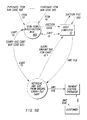
- Foodway places an order with CerealCo for 12 cartons of flakes cereal boxes, 24 cartons of oat rings cereal boxes, and 3 cartons of nuggets cereal boxes. Foodway intends to redistribute these cereal boxes, once received at the receiving point, to its stores as follows:
- the Foodway order including addressing information for the destination stores, is transmitted to CerealCo in any convenient way, e.g., by telephone, telecopy, or the like, or alternatively by an electronic data interchange (EDI) technique.
- the order is conventionally input into a host computer 1402, e.g., via a scanner, a keyboard, or the like, or directly from a Foodway computer 1404 via an EDI link 1410.
- the CerealCo host computer 1402 consolidates the Foodway order with other orders and prints a special pick-list form 1420, e.g., by transmitting the appropriate data to a base station 12 for printing on a printer 33a.
- the pick-list form 1420 is printed on blank stock that includes a series of blank peel-off labels (for use as bar code labels as discussed below).
- the pick-list form 1420 includes appropriate order-filling information, e.g., the specific locations of warehouse bays 1305, 1306, 1307 from which cartons 1205 of cereal boxes 1210 are to be drawn to fill the orders.
- the pick-list form 1420 as printed also includes bar-coded destination address labels 1450, printed on the aforementioned blank labels, that are applied to cartons 1205 of cereal boxes 1210 stored at the location(s) specified on the pick-list form 1420.
- the pick-list form 1420 thus serves as a machine-readable destination-information storage device comprising transferable machine-readable destination-information modules.
- the labels 1450 may be applied manually and/or with suitable automatic means.
- the destination information encoded in the address labels 1250 may be as detailed as desired, perhaps even including the shelf locations at which the cereal boxes in question are displayed at various Foodway stores. This information may be supplied by Foodway, e.g., via the EDI link 1410.
- the now-labeled cartons 1205 of cereal boxes 1210 are transported by suitable means (not shown) to an order filling station, where all cartons 1205 destined for the Foodway stores are consolidated for shipment into, e.g., one crate 1310.
- suitable means not shown
- all cartons 1205 destined for the Foodway stores are consolidated for shipment into, e.g., one crate 1310.
- the destination information included on the destination address labels 1420 may be read using a terminal 15 or other reading means to aid in the sorting and order-consolidation process.
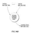
- the carton bar codes 1250 are read by a terminal 15 or other suitable means.
- the information read from the carton bar codes 1250 is used to build a shipment list, e.g., in the memory 31 of a base station 12 at the order filling point, comprising identification information about each carton 1205 in the Foodway shipment.
- a bar-coded crate shipping label 1350 is printed (e.g., at the printer 33a of a base station 12) and applied to the exterior of the crate.
- the bar code label 1350 may be stenciled, spray-painted, or otherwise applied to the crate.
- the shipping label 1350 may include virtually any information desired, e.g., the point of origin of the crate, the destination, the contact person(s) at either the origin or the destination, insurance information, and the like.
- the crate 1310 with its bar-coded shipping label 1350 is shipped by any convenient means, e.g., a commercial carrier company, to Foodway's central warehouse 1308.
- a terminal 15 may be used to read the shipping label 1350 when the crate 1310 physically leaves the CerealCo facility; shipping and departure information may be transmitted to the CerealCo host computer 1404 and thereby to the Foodway host computer 1402 via the EDI link 1410 in a conventional manner.
- the carrier company may use a terminal 15 or other suitable means to read information from the crate shipping label 1350 as needed; additional bar codes maybe printed and applied to the exterior of the crate as needed, e.g., to indicate handling instructions for the carrier company's personnel at various stages of the journey.
- this information may be transmitted to the carrier company's host computer 1510, where it may be made available as a status report to the Foodway and CerealCo host computers 1402 and 1404 via EDI links 1515 and 1516, respectively.
- Foodway personnel may use a terminal 15 or other suitable means to read information from the crate shipping label 1350.
- the fact of receipt and other information so read may be communicated to and stored in Foodway's host computer 1402, which may then relay the information to the CerealCo host computer 1404 and generate a payment order to be transmitted to a bank host computer 1520 via an EDI link 1525.
- each carton bar code label 1250 is read using a terminal 15 or other suitable means.
- the destination information encoded in the bar code labels 1250 maybe used in the manner described above for routing of the cartons 1205 to their respective specific destination Foodway stores.
- the information obtained by reading the bar code labels 1250 may be used to enter a lookup table, e.g., in the host computer's disk storage 24, in a conventional manner for this purpose.
- Similar techniques maybe used by Foodway personnel for processing incoming shipments that do not include bar code labels.
- the destination information in question may be read (e.g., with an OCR scanner (not shown) and/or by manual keyboard entry using the keyboard 48 of a terminal 15); carton bar code labels 1250 may then be printed and applied to incoming cartons 1205, and cereal-box bar code labels 1215 may even be printed and applied to individual cereal boxes 1210, in the manner described above.
- the retail store described above may use a system in accordance with the invention to manage its inventory more effectively.
- the shelf item labels 1610 normally include human-readable information identifying specific items and stating the price; they also include bar-coded order information that can be a detailed as desired, e.g., the stock number of the item in question, the reorder limit (i.e., the lowest acceptable on-the-shelf count below which reordering is desired) and perhaps even information about the vendor or vendors who supply the item.
- An inventory clerk may use a terminal 15 to read a shelf item label 1310.
- the terminal 15 may also be used to input an actual count of the items on the shelf, e.g., by reading bar codes (such as cereal-box bar codes 1215) from each individual item or by manually counting the items and entering the count on the keyboard 48 of the terminal 15. If the actual count is below the reorder limit, the CPU 40 of the terminal 15 generates a reorder message and transmits it to the host computer 10. Alternatively or in addition, the actual count itself may of course likewise be transmitted to the host computer 10 for storage, e.g., in disk storage 24, allowing the count information to be used in generating reports in any convenient manner.
- bar codes such as cereal-box bar codes 1215
Landscapes
- Physics & Mathematics (AREA)
- Engineering & Computer Science (AREA)
- General Physics & Mathematics (AREA)
- Health & Medical Sciences (AREA)
- Electromagnetism (AREA)
- General Health & Medical Sciences (AREA)
- Toxicology (AREA)
- Artificial Intelligence (AREA)
- Computer Vision & Pattern Recognition (AREA)
- Quality & Reliability (AREA)
- Theoretical Computer Science (AREA)
- Cash Registers Or Receiving Machines (AREA)
- Management, Administration, Business Operations System, And Electronic Commerce (AREA)
- Financial Or Insurance-Related Operations Such As Payment And Settlement (AREA)
- Warehouses Or Storage Devices (AREA)
Applications Claiming Priority (2)
| Application Number | Priority Date | Filing Date | Title |
|---|---|---|---|
| US61266490A | 1990-11-13 | 1990-11-13 | |
| US612664 | 1990-11-13 |
Publications (3)
| Publication Number | Publication Date |
|---|---|
| EP0485996A2 true EP0485996A2 (fr) | 1992-05-20 |
| EP0485996A3 EP0485996A3 (en) | 1993-10-06 |
| EP0485996B1 EP0485996B1 (fr) | 1996-04-03 |
Family
ID=24454129
Family Applications (1)
| Application Number | Title | Priority Date | Filing Date |
|---|---|---|---|
| EP91119370A Expired - Lifetime EP0485996B1 (fr) | 1990-11-13 | 1991-11-13 | Système flexible d'enregistrement-en-sortie d'articles et de gestion d'inventaire |
Country Status (6)
| Country | Link |
|---|---|
| EP (1) | EP0485996B1 (fr) |
| JP (1) | JPH04287163A (fr) |
| AT (1) | ATE136387T1 (fr) |
| CA (1) | CA2055363A1 (fr) |
| DE (1) | DE69118485T2 (fr) |
| ES (1) | ES2085401T3 (fr) |
Cited By (4)
| Publication number | Priority date | Publication date | Assignee | Title |
|---|---|---|---|---|
| US5401944A (en) * | 1990-11-20 | 1995-03-28 | Symbol Technologies, Inc. | Traveler security and luggage control system |
| FR2718623A1 (fr) * | 1994-04-13 | 1995-10-20 | Gempsy Sa | Procédé et dispositifs de caisses-express pour la grande et petite distribution. |
| US5497822A (en) * | 1994-07-20 | 1996-03-12 | Venture Enterprises Inc | Shoe for use on continuous casting machines and method of use |
| EP1688851A2 (fr) | 1996-08-02 | 2006-08-09 | Symbol Technologies, Inc. | Système et procédé de récupération des données |
Families Citing this family (3)
| Publication number | Priority date | Publication date | Assignee | Title |
|---|---|---|---|---|
| US7333947B2 (en) | 2000-11-13 | 2008-02-19 | Anoto Ab | Network-based system |
| CN107323931A (zh) * | 2017-06-13 | 2017-11-07 | 重庆都英科技有限公司 | 一种钣金信息化存取的方法及其钣金存放转运装置 |
| CN113998352B (zh) * | 2021-10-12 | 2023-09-12 | 北京迈格威科技有限公司 | 拣选调度方法、装置、电子设备、存储介质及仓储系统 |
Citations (2)
| Publication number | Priority date | Publication date | Assignee | Title |
|---|---|---|---|---|
| EP0210963A2 (fr) * | 1985-08-02 | 1987-02-04 | SINTEL ORSINI S.p.A. | Caisse pour l'émission et la confirmation de carte-clef optique et/ou magnétique |
| EP0339266A2 (fr) * | 1988-04-27 | 1989-11-02 | Ascom Autelca Ag | Aménagement pour le service des clients dans un local de vente libre-service |
-
1991
- 1991-11-13 AT AT91119370T patent/ATE136387T1/de not_active IP Right Cessation
- 1991-11-13 EP EP91119370A patent/EP0485996B1/fr not_active Expired - Lifetime
- 1991-11-13 DE DE69118485T patent/DE69118485T2/de not_active Expired - Lifetime
- 1991-11-13 ES ES91119370T patent/ES2085401T3/es not_active Expired - Lifetime
- 1991-11-13 CA CA002055363A patent/CA2055363A1/fr not_active Abandoned
- 1991-11-13 JP JP3297297A patent/JPH04287163A/ja active Pending
Patent Citations (2)
| Publication number | Priority date | Publication date | Assignee | Title |
|---|---|---|---|---|
| EP0210963A2 (fr) * | 1985-08-02 | 1987-02-04 | SINTEL ORSINI S.p.A. | Caisse pour l'émission et la confirmation de carte-clef optique et/ou magnétique |
| EP0339266A2 (fr) * | 1988-04-27 | 1989-11-02 | Ascom Autelca Ag | Aménagement pour le service des clients dans un local de vente libre-service |
Cited By (4)
| Publication number | Priority date | Publication date | Assignee | Title |
|---|---|---|---|---|
| US5401944A (en) * | 1990-11-20 | 1995-03-28 | Symbol Technologies, Inc. | Traveler security and luggage control system |
| FR2718623A1 (fr) * | 1994-04-13 | 1995-10-20 | Gempsy Sa | Procédé et dispositifs de caisses-express pour la grande et petite distribution. |
| US5497822A (en) * | 1994-07-20 | 1996-03-12 | Venture Enterprises Inc | Shoe for use on continuous casting machines and method of use |
| EP1688851A2 (fr) | 1996-08-02 | 2006-08-09 | Symbol Technologies, Inc. | Système et procédé de récupération des données |
Also Published As
| Publication number | Publication date |
|---|---|
| CA2055363A1 (fr) | 1992-05-14 |
| JPH04287163A (ja) | 1992-10-12 |
| DE69118485D1 (de) | 1996-05-09 |
| EP0485996B1 (fr) | 1996-04-03 |
| DE69118485T2 (de) | 1996-11-07 |
| ATE136387T1 (de) | 1996-04-15 |
| ES2085401T3 (es) | 1996-06-01 |
| EP0485996A3 (en) | 1993-10-06 |
Similar Documents
| Publication | Publication Date | Title |
|---|---|---|
| US5393965A (en) | Flexible merchandise checkout and inventory management system | |
| US5646389A (en) | Inventory management system using coded re-order information | |
| US5984182A (en) | Scan-ahead system for processing merchandise at a checkout register | |
| US6189789B1 (en) | Method and system for a merchandise checkout system | |
| CN101156187B (zh) | 减少误报警、无效安全去激活和内部偷窃的设备、系统和方法 | |
| US5729697A (en) | Intelligent shopping cart | |
| CN100520838C (zh) | 自助收款装置 | |
| US6354496B1 (en) | Method for self service checkout | |
| Codes | their Applications | |
| US3819012A (en) | Merchandise handling and identifying system | |
| US20020050526A1 (en) | Portable shopping and order fulfillment system | |
| LT5774B (lt) | Pirkimo sistema savitarnos būdu | |
| JPH10105832A (ja) | セルフ・サービス・ショピング・システム及び購入商品記録方法 | |
| CN1694122A (zh) | 印刷物品的电子标签购物系统 | |
| US6776333B2 (en) | Customer management system | |
| Jones et al. | The adoption of RFID technology in the retail supply chain | |
| EP0485996B1 (fr) | Système flexible d'enregistrement-en-sortie d'articles et de gestion d'inventaire | |
| US7191950B1 (en) | Portable tendering and customer service stations and related systems and method | |
| RU2684490C2 (ru) | Способ и система розничной продажи товаров | |
| CN101916416A (zh) | 商品销售数据处理装置及方法 | |
| CN205827569U (zh) | 超市便捷电子购物装置 | |
| US7311251B1 (en) | System and method of completing a transaction involving goods tagged with RFID labels | |
| JPH0773380A (ja) | Posシステム | |
| CN1042980C (zh) | 购进物品结算及库存柔性管理系统 | |
| JP2010113391A (ja) | 商品荷揃えシステム及び方法 |
Legal Events
| Date | Code | Title | Description |
|---|---|---|---|
| PUAI | Public reference made under article 153(3) epc to a published international application that has entered the european phase |
Free format text: ORIGINAL CODE: 0009012 |
|
| AK | Designated contracting states |
Kind code of ref document: A2 Designated state(s): AT DE ES FR GB IT |
|
| PUAL | Search report despatched |
Free format text: ORIGINAL CODE: 0009013 |
|
| AK | Designated contracting states |
Kind code of ref document: A3 Designated state(s): AT DE ES FR GB IT |
|
| 17P | Request for examination filed |
Effective date: 19940406 |
|
| 17Q | First examination report despatched |
Effective date: 19940824 |
|
| GRAH | Despatch of communication of intention to grant a patent |
Free format text: ORIGINAL CODE: EPIDOS IGRA |
|
| GRAA | (expected) grant |
Free format text: ORIGINAL CODE: 0009210 |
|
| AK | Designated contracting states |
Kind code of ref document: B1 Designated state(s): AT DE ES FR GB IT |
|
| REF | Corresponds to: |
Ref document number: 136387 Country of ref document: AT Date of ref document: 19960415 Kind code of ref document: T |
|
| ITF | It: translation for a ep patent filed | ||
| REF | Corresponds to: |
Ref document number: 69118485 Country of ref document: DE Date of ref document: 19960509 |
|
| REG | Reference to a national code |
Ref country code: ES Ref legal event code: FG2A Ref document number: 2085401 Country of ref document: ES Kind code of ref document: T3 |
|
| ET | Fr: translation filed | ||
| PLBE | No opposition filed within time limit |
Free format text: ORIGINAL CODE: 0009261 |
|
| STAA | Information on the status of an ep patent application or granted ep patent |
Free format text: STATUS: NO OPPOSITION FILED WITHIN TIME LIMIT |
|
| 26N | No opposition filed | ||
| REG | Reference to a national code |
Ref country code: GB Ref legal event code: IF02 |
|
| PGFP | Annual fee paid to national office [announced via postgrant information from national office to epo] |
Ref country code: AT Payment date: 20101022 Year of fee payment: 20 Ref country code: FR Payment date: 20101109 Year of fee payment: 20 |
|
| PGFP | Annual fee paid to national office [announced via postgrant information from national office to epo] |
Ref country code: DE Payment date: 20101130 Year of fee payment: 20 |
|
| PGFP | Annual fee paid to national office [announced via postgrant information from national office to epo] |
Ref country code: GB Payment date: 20101022 Year of fee payment: 20 Ref country code: IT Payment date: 20101118 Year of fee payment: 20 |
|
| PGFP | Annual fee paid to national office [announced via postgrant information from national office to epo] |
Ref country code: ES Payment date: 20101119 Year of fee payment: 20 |
|
| REG | Reference to a national code |
Ref country code: DE Ref legal event code: R071 Ref document number: 69118485 Country of ref document: DE |
|
| REG | Reference to a national code |
Ref country code: DE Ref legal event code: R071 Ref document number: 69118485 Country of ref document: DE |
|
| REG | Reference to a national code |
Ref country code: GB Ref legal event code: PE20 Expiry date: 20111112 |
|
| REG | Reference to a national code |
Ref country code: AT Ref legal event code: MK07 Ref document number: 136387 Country of ref document: AT Kind code of ref document: T Effective date: 20111113 |
|
| PG25 | Lapsed in a contracting state [announced via postgrant information from national office to epo] |
Ref country code: GB Free format text: LAPSE BECAUSE OF EXPIRATION OF PROTECTION Effective date: 20111112 |
|
| PG25 | Lapsed in a contracting state [announced via postgrant information from national office to epo] |
Ref country code: DE Free format text: LAPSE BECAUSE OF EXPIRATION OF PROTECTION Effective date: 20111114 |
|
| REG | Reference to a national code |
Ref country code: ES Ref legal event code: FD2A Effective date: 20140827 |
|
| PG25 | Lapsed in a contracting state [announced via postgrant information from national office to epo] |
Ref country code: ES Free format text: LAPSE BECAUSE OF EXPIRATION OF PROTECTION Effective date: 20111114 |