EP0483698A1 - Bobines d'indication de la position de capteurs utilisées pour les examens de magnétoencéphalographe et les moyens pour les attacher à la tête - Google Patents
Bobines d'indication de la position de capteurs utilisées pour les examens de magnétoencéphalographe et les moyens pour les attacher à la tête Download PDFInfo
- Publication number
- EP0483698A1 EP0483698A1 EP91118278A EP91118278A EP0483698A1 EP 0483698 A1 EP0483698 A1 EP 0483698A1 EP 91118278 A EP91118278 A EP 91118278A EP 91118278 A EP91118278 A EP 91118278A EP 0483698 A1 EP0483698 A1 EP 0483698A1
- Authority
- EP
- European Patent Office
- Prior art keywords
- head
- coils
- fastening strips
- attaching
- position indicator
- Prior art date
- Legal status (The legal status is an assumption and is not a legal conclusion. Google has not performed a legal analysis and makes no representation as to the accuracy of the status listed.)
- Granted
Links
- 238000002474 experimental method Methods 0.000 title claims abstract description 5
- 239000000463 material Substances 0.000 claims abstract description 8
- 238000000034 method Methods 0.000 claims description 16
- 239000004020 conductor Substances 0.000 claims description 11
- 239000004033 plastic Substances 0.000 claims description 3
- 229920003023 plastic Polymers 0.000 claims description 3
- 238000005452 bending Methods 0.000 claims description 2
- 238000000059 patterning Methods 0.000 claims 2
- 238000000151 deposition Methods 0.000 claims 1
- 239000003822 epoxy resin Substances 0.000 abstract description 6
- 229920000647 polyepoxide Polymers 0.000 abstract description 6
- 238000005266 casting Methods 0.000 abstract 1
- 210000003128 head Anatomy 0.000 description 38
- 238000005259 measurement Methods 0.000 description 15
- 230000005291 magnetic effect Effects 0.000 description 11
- 238000010276 construction Methods 0.000 description 4
- 239000010408 film Substances 0.000 description 3
- 238000002582 magnetoencephalography Methods 0.000 description 3
- 230000007177 brain activity Effects 0.000 description 2
- 238000012552 review Methods 0.000 description 2
- 239000000758 substrate Substances 0.000 description 2
- 239000002390 adhesive tape Substances 0.000 description 1
- 238000010420 art technique Methods 0.000 description 1
- 210000004556 brain Anatomy 0.000 description 1
- 230000003925 brain function Effects 0.000 description 1
- 230000005670 electromagnetic radiation Effects 0.000 description 1
- 239000004744 fabric Substances 0.000 description 1
- 239000011152 fibreglass Substances 0.000 description 1
- 230000004907 flux Effects 0.000 description 1
- 239000006260 foam Substances 0.000 description 1
- 230000006698 induction Effects 0.000 description 1
- 239000011810 insulating material Substances 0.000 description 1
- 230000000149 penetrating effect Effects 0.000 description 1
- 239000000700 radioactive tracer Substances 0.000 description 1
- 238000011160 research Methods 0.000 description 1
- 210000004761 scalp Anatomy 0.000 description 1
- 230000002123 temporal effect Effects 0.000 description 1
- 239000010409 thin film Substances 0.000 description 1
Images


Classifications
-
- A—HUMAN NECESSITIES
- A61—MEDICAL OR VETERINARY SCIENCE; HYGIENE
- A61B—DIAGNOSIS; SURGERY; IDENTIFICATION
- A61B5/00—Measuring for diagnostic purposes; Identification of persons
- A61B5/24—Detecting, measuring or recording bioelectric or biomagnetic signals of the body or parts thereof
- A61B5/242—Detecting biomagnetic fields, e.g. magnetic fields produced by bioelectric currents
- A61B5/245—Detecting biomagnetic fields, e.g. magnetic fields produced by bioelectric currents specially adapted for magnetoencephalographic [MEG] signals
Definitions
- This invention is about coils used in magnetoencephalographic experiments to determine the position and orientation of the magnetometer, and a means of attaching the said coils to the head.
- MEG magnetoencephalography
- the method is gaining gradually a more important role in medical research and diagnostics.
- it is possible to investigate the brain functions and disorders in a human being without touching the person or exposing him to electromagnetic radiation or radioactive tracers.
- EEG electroencephalogram
- the magnetoencephalogram suffers far less from distortions caused by inhomogeneities in the conductivity of the human tissue.
- Instruments used in MEG should be able to detect magnetic signals whose magnetic flux density is typically 100 fT or less. In addition, the measurement is to be performed simultaneously at several locations; the measurement of even more than one hundred magnetic signals from all over the head is necessary.
- the only sensor capable of detecting these minute signals is the so-called Superconducting Quantum Interference Device (SQUID) magnetometer. The operation of the device has been explained in detail in an article in Journal of Low Temperature Physics, volume 76 (1989), issue 5/6, pp. 287-386.
- SQUID Superconducting Quantum Interference Device
- a locating method employing at least three transmitter coils are attached to the subject's head; the positions and orientations of the coils are accurately determined prior to the measurement by some other means.
- the system also includes a current supply, a magnetic field detector, and a computer to determine the coordinates of the coils on the basis of the measured magnetic field.
- the system is capable of automatically determining the position and orientation of the magnetometer during the measurement.
- a multichannel SQUID-magnetometer is particularly useful (cf. Review of Scientific Instruments, volume 58 (1987), issue 11, pp. 2145-2156 or Advances in Biomagnetism, edited by S. J. Williamson, M. Hoke, G.
- Another known position indicator system (US4793355) employs orthogonal coil sets comprising three coils as transmitters and receivers; the method is based on the induction principle. The receiver coils are attached to the head of the subject and the transmitter coils to the magnetometer.
- the coils are wound, by hand or by other means, from wire around a non-magnetic core, as in the references cited above. Three such coils are cast in epoxy resin, forming a coil set.
- the coil sets are attached to the subject's head by means of a flexible headband or with adhesive tape.
- the main drawback of the prior-art technique is that the coil sets are too big to be attached to the actual measurement area, i.e. between the head and the SQUID magnetometer.
- the present techniques do not provide a possibility to attach the coils firmly at an arbitrary position on the cortex.
- the area where the attachment of the coils is possible is limited, and the hair prevents a firm adhering of the coils with tape.
- the accuracy of dimensions of wire-wound multi-turn coils is not very good, and taking into account the stray fields or eliminating them is very elaborate.
- the determination of the effective dipole moment of the coil is therefore difficult; the error reflects itself correspondingly in the results of the sensor position determination.
- DE-2 206 913 deals with a stiff headband to be placed around the subject's head for attaching EEG electrodes.
- the headband is hinged on the back, and it is tightened around the head using a punched rubber strap or, alternatively, a spring-loaded hinge.
- the electrodes are attached to the headband via stiff connector wires.
- the wires are bent in a spring-like manner to press the electrodes against the head.
- the solution presented in the said reference has several drawbacks. Due to the completely stiff structure, the construction cannot be made flat enough not to considerably hamper the ease of operation of the magnetometer.
- the multichannel magnetometer must be placed rather far from the head, resulting in a substantially deteriorated signal-to-noise ratio.
- the means of attaching the electrodes (Fig. 1 of the reference cited above) is not suitable for position indicator coils because it utilizes only one support arm: a well-defined position and orientation (along the tangent plane) on the head, accurate enough for the MEG method and stationary during the measurement, cannot be guaranteed; coils may move easily during the measurement, for instance, when moving the magnetometer.
- a third drawback is that the electrodes can only be attached to certain predetermined positions.
- DE-2 124 704 describes an elastic, hollow headband used to attach electrodes.
- the electrodes are located on the inside surface of the headband, and when the headband is pressurized, e.g., by compressed air the electrodes are pressed against the head of the subject. This is not a solution either, because the construction cannot be made flat enough not to hamper the placing the magnetometer as close to the head as possible.
- the electrodes can be attached only to predetermined places.
- EP-A2-399 499 magnetometer elements are attached to a stiff shell (cf. Fig. 6 of the reference).
- the method is not suitable for position indicator coils, since the resulting structure is completely stiff.
- the coils cannot be attached freely anywhere on the cortex on every subject so that the distance from the magnetometers to the head would not substantially increase.
- a solution to this problem would be an individual, tight-fitting shell for each subject, but this would certainly considerably annoy the subject.
- making individual shells would make clinical measurements with patients more elaborate and increase the time consumption and cost for preparing the measurement excessively.
- EP-A3-199 214 mentions two means of attaching electrodes to the subject's head.
- the first one employs an elastic cap which can be set very tightly against the head.
- the second method includes a stiff headband which can be tightened around the head. A stiff strip is then attached to this headband in a fixed and stiff manner; this strip goes over the head.
- Neither of the two methods is suitable for position indicator coils, since the elastic cap does not guarantee that the coils are not moved during the measurement and the stiff construction does not allow a free selection of measurement points on the cortex. The stiff construction is also uncomfortable for the subject.
- planar coils fabricated using thin film or thick film techniques and encapsulating them inside epoxy resin as well as the use of parallel conductors patterned on flexible, insulating substrates is known as such, for example, from DE-A1-3 135 962, DE-C3-2 315 498, US-7 749 946, IEEE Transactions on Magnetics, vol. MAG-17, issue 1 (January 1981), pp. 400-401 and DE-A1-3 148 192. None of the features described in the above references solves alone the problem how to make a small, dimensionally accurate coil the stray fields of which are negligible, including current supply leads, and which is, in addition, as flat as possible and can be reliably and easily attached to the head.
- the most important advantage of the invention is that the position indicator coils can be firmly and easily attached to the head without sacrificing the free choice of the place of attachment or the comfort of the subject.
- the coil set can be made so thin that it fits without any trouble between the subject's head and the magnetometer.
- the fastening strips made of a thin, non-stretching and flexible material, wide enough to prevent lateral movements, guarantee that the coils stay in place during the measurement and firmly press the coils against the head.
- planar coils fabricated with thin- or thick film techniques combined with the use of the headband and the fastening strips, described in claims 1-3, in a common structure is the key to functionality of the concept.
- the planar coils can be made very thin, and with the use of cast epoxy resin the coils and their necessary contact leads can be encapsulated to protect them mechanically for increased reliability and to attach the coils to the fastening strips.
- the cast epoxy resin can be used to form the small elevations or knobs necessary for supporting the coil element.
- the fastening strips also include the current supply leads; when the return conductors run symmetrically on both sides of the supply conductor, the stray fields due to them are minimized.
- Figure 1 represents the headband portion and Figure 2 the coil portion so that the part against the head is visible.
- Figure 3 the geometry of the coil is shown schematically, and
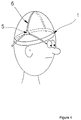
- Fig. 4 represents the invention attached to the head of the subject.
- the headband (1) shown in Fig. 1 is made of fabric or other similar material and its inside has been covered with material, which glides poorly on the skin, e.g. thin foam plastic.
- the outside surface of the headband has been covered with material (3) onto which the fastening strips of the coil assembly, shown in Fig. 2, adhere.
- material (3) onto which the fastening strips of the coil assembly, shown in Fig. 2, adhere.
- This can be accomplished using, e.g. commercially available VelcroTM tape, which has a plurality of small hooks.
- the headband has a buckle (4) or another similar device with which the headband is fixed firmly around the head.
- the coil assembly depicted in Fig. 2, comprises the planar coil set (5) attached to at least three long enough fastening strips (6) made of a thin, flexible and inelastic material, e.g. fiber glass.
- each of the fastening strips has a planar coil set (5) or a separate planar coil (5').
- the strips ought to be so thin that they bend easily following the curvature of the head but, at the same time, thick enough to exert a force sufficient to press the coils against the head.
- the strips must be wide enough to prevent bending laterally.
- the underside of the strips has been covered with material (7) adhering to the outside surface of the head band, such as VelcroTM tape.
- the coil set has at least three small elevations (8) so that the coil set will settle firmly in the tangent plane of the head, leaning on the knobs (8).
- the coil set (5) comprises at least three coils fabricated using thin or thick film techniques. Also, the separate coils (5') have been made with the same methods. Each coil consists of, for example, of two spirals laid on top of each other so that the spirals are mirror images. Then, the current can be routed from one spiral to another simply by a via in the insulating material in between. The magnetic fields of the two spirals add to each other, and the stray fields of the conductors can be minimized by having the conductors on top of each other on the substrate plane. Figure 3 shows this situation. The supply leads to the coils should be made as twisted pairs or coaxial cables to minimize stray fields.
- the current supply leads have been patterned with a printed-circuit board technique on the fastening strips, is preferable.
- the stray fields can be minimized in that case so that the middle conductor is symmetrically surrounded by two return conductors.
- the coils are contacted with the supply leads using, for example, ultrasonic bonding and thin contact wires.
- the coils with the contacts can finally be encapsulated in epoxy resin or other cast plastics.
- a coil assembly so fabricated has a thickness of only a few millimeters.
- the headband shown in Fig. 1 is first set firmly around the head. Thereafter, the coil assembly is positioned to the desired place and the fastening strips are pressed, following tightly the shape of the head, on the headband.
- Figure 4 shows the invention attached to the head.
- the knobs of the coil set, penetrating through hair, are leaning against the head, and to keep the coils firmly in place and oriented in the tangent plane of the head.
- the properties of the fastening strips described earlier guarantee that the coils are pressed against the head and that the coil set cannot move during the measurement in any direction.
- the fastening strips are first detached from the headband and thereafter the headband is loosened.
- the fastening strips need not be of equal length.
- one of the strips can be made longer than the others, facilitating the connection to the headband that is most far apart.
- the strips can be equipped with extensions, too.
Landscapes
- Life Sciences & Earth Sciences (AREA)
- Health & Medical Sciences (AREA)
- Medical Informatics (AREA)
- Animal Behavior & Ethology (AREA)
- Pathology (AREA)
- Engineering & Computer Science (AREA)
- Biomedical Technology (AREA)
- Heart & Thoracic Surgery (AREA)
- Physics & Mathematics (AREA)
- Molecular Biology (AREA)
- Surgery (AREA)
- Biophysics (AREA)
- General Health & Medical Sciences (AREA)
- Public Health (AREA)
- Veterinary Medicine (AREA)
- Measurement And Recording Of Electrical Phenomena And Electrical Characteristics Of The Living Body (AREA)
- Measuring Magnetic Variables (AREA)
- Agricultural Chemicals And Associated Chemicals (AREA)
- Investigating Or Analysing Biological Materials (AREA)
Applications Claiming Priority (2)
| Application Number | Priority Date | Filing Date | Title |
|---|---|---|---|
| FI905397A FI89130C (fi) | 1990-11-01 | 1990-11-01 | Lokaliseringsspolar och anordning foer deras faestning vid huvudet foer anvaendning i magnetoenkefalografiska maetningar |
| FI905397 | 1990-11-01 |
Publications (2)
| Publication Number | Publication Date |
|---|---|
| EP0483698A1 true EP0483698A1 (fr) | 1992-05-06 |
| EP0483698B1 EP0483698B1 (fr) | 1995-04-26 |
Family
ID=8531349
Family Applications (1)
| Application Number | Title | Priority Date | Filing Date |
|---|---|---|---|
| EP91118278A Expired - Lifetime EP0483698B1 (fr) | 1990-11-01 | 1991-10-26 | Bobines d'indication de la position de capteurs utilisées pour les examens de magnétoencéphalographe et les moyens pour les attacher à la tête |
Country Status (7)
| Country | Link |
|---|---|
| US (1) | US5323777A (fr) |
| EP (1) | EP0483698B1 (fr) |
| JP (1) | JPH04314424A (fr) |
| AT (1) | ATE121607T1 (fr) |
| CA (1) | CA2053762A1 (fr) |
| DE (1) | DE69109234T2 (fr) |
| FI (1) | FI89130C (fr) |
Cited By (5)
| Publication number | Priority date | Publication date | Assignee | Title |
|---|---|---|---|---|
| WO2005067789A1 (fr) * | 2004-01-19 | 2005-07-28 | Elekta Ab (Publ) | Procede de separation de signaux multicanaux les uns des autres produits par des sources ca et cc |
| WO2018092114A1 (fr) * | 2016-11-21 | 2018-05-24 | St. Jude Medical International Holding S.À R.L. | Générateur de champ magnétique fluoroluminescent |
| IT201600131510A1 (it) * | 2016-12-28 | 2018-06-28 | Fond Ospedale San Camillo | Sistema di ritenzione per l’uso in magnetoencefalografia (MEG). |
| US10321848B2 (en) | 2013-11-06 | 2019-06-18 | St. Jude Medical International Holding S.À R.L. | Magnetic field generator with minimal image occlusion and minimal impact on dimensions in C-arm x-ray environments |
| US11786694B2 (en) | 2019-05-24 | 2023-10-17 | NeuroLight, Inc. | Device, method, and app for facilitating sleep |
Families Citing this family (32)
| Publication number | Priority date | Publication date | Assignee | Title |
|---|---|---|---|---|
| US5442289A (en) * | 1989-07-31 | 1995-08-15 | Biomagnetic Technologies, Inc. | Biomagnetometer having flexible sensor |
| JP3204542B2 (ja) * | 1992-07-24 | 2001-09-04 | 株式会社東芝 | 磁場源測定装置 |
| US5743854A (en) * | 1994-03-29 | 1998-04-28 | The Regents Of The University Of California | Method and apparatus for inducing and localizing epileptiform activity |
| DE69530798T2 (de) * | 1995-02-15 | 2004-03-18 | Exogen, Inc. | Positionierungsvorrichtung |
| US7196514B2 (en) * | 2002-01-15 | 2007-03-27 | National University Of Singapore | Multi-conductive ferromagnetic core, variable permeability field sensor and method |
| US6853186B2 (en) | 2002-01-15 | 2005-02-08 | National University Of Singapore | Variable permeability magnetic field sensor and method |
| US6856823B2 (en) * | 2002-06-18 | 2005-02-15 | Ascension Technology Corporation | Spiral magnetic transmitter for position measurement system |
| US7672707B2 (en) * | 2003-06-11 | 2010-03-02 | Japan Science And Technology Agency | Sensor for magnetoencephalography meter and supermultichannel magnetoencephalography meter system using the same |
| US8104892B2 (en) * | 2004-12-03 | 2012-01-31 | The Invention Science Fund I, Llc | Vision modification with reflected image |
| US7344244B2 (en) * | 2004-12-03 | 2008-03-18 | Searete, Llc | Adjustable lens system with neural-based control |
| US7390088B2 (en) * | 2004-12-03 | 2008-06-24 | Searete Llc | Adjustable lens system with neural-based control |
| US7470027B2 (en) * | 2004-12-03 | 2008-12-30 | Searete Llc | Temporal vision modification |
| US7931373B2 (en) * | 2004-12-03 | 2011-04-26 | The Invention Science Fund I, Llc | Vision modification with reflected image |
| US8244342B2 (en) * | 2004-12-03 | 2012-08-14 | The Invention Science Fund I, Llc | Method and system for adaptive vision modification |
| US7656569B2 (en) * | 2004-12-03 | 2010-02-02 | Searete Llc | Vision modification with reflected image |
| US7594727B2 (en) * | 2004-12-03 | 2009-09-29 | Searete Llc | Vision modification with reflected image |
| US7350919B2 (en) * | 2004-12-03 | 2008-04-01 | Searete Llc | Vision modification with reflected image |
| US7334892B2 (en) * | 2004-12-03 | 2008-02-26 | Searete Llc | Method and system for vision enhancement |
| US7486988B2 (en) * | 2004-12-03 | 2009-02-03 | Searete Llc | Method and system for adaptive vision modification |
| US7334894B2 (en) * | 2004-12-03 | 2008-02-26 | Searete, Llc | Temporal vision modification |
| US9155483B2 (en) | 2004-12-03 | 2015-10-13 | The Invention Science Fund I, Llc | Vision modification with reflected image |
| DE102005045912B4 (de) * | 2005-09-26 | 2010-06-02 | Armatix Gmbh | Selbsthemmende Waffenlaufsicherung und Verfahren zum Sichern eines Waffenlaufs |
| AU2007224993A1 (en) * | 2006-03-15 | 2007-09-20 | Compumedics Limited | Ultrasound in magnetic spatial imaging apparatus |
| US20080183064A1 (en) * | 2007-01-30 | 2008-07-31 | General Electric Company | Multi-sensor distortion detection method and system |
| FR2992543B1 (fr) * | 2012-06-29 | 2015-05-29 | Commissariat Energie Atomique | Procede de localisation d'une activite cerebrale |
| CN104739405B (zh) * | 2015-04-15 | 2017-04-12 | 重庆博恩富克医疗设备有限公司 | 一种脑水肿信号检测装置及方法 |
| JP7069563B2 (ja) * | 2016-06-07 | 2022-05-18 | 株式会社リコー | マーカコイル、マーカコイルユニット |
| US11723579B2 (en) | 2017-09-19 | 2023-08-15 | Neuroenhancement Lab, LLC | Method and apparatus for neuroenhancement |
| US11717686B2 (en) | 2017-12-04 | 2023-08-08 | Neuroenhancement Lab, LLC | Method and apparatus for neuroenhancement to facilitate learning and performance |
| WO2019133997A1 (fr) | 2017-12-31 | 2019-07-04 | Neuroenhancement Lab, LLC | Système et procédé de neuro-activation pour améliorer la réponse émotionnelle |
| US11364361B2 (en) | 2018-04-20 | 2022-06-21 | Neuroenhancement Lab, LLC | System and method for inducing sleep by transplanting mental states |
| WO2020056418A1 (fr) | 2018-09-14 | 2020-03-19 | Neuroenhancement Lab, LLC | Système et procédé d'amélioration du sommeil |
Citations (2)
| Publication number | Priority date | Publication date | Assignee | Title |
|---|---|---|---|---|
| US3998213A (en) * | 1975-04-08 | 1976-12-21 | Bio-Volt Corporation | Self-adjustable holder for automatically positioning electroencephalographic electrodes |
| GB2083952A (en) * | 1980-09-11 | 1982-03-31 | Asahi Chemical Ind | Microcoil Assembly |
Family Cites Families (11)
| Publication number | Priority date | Publication date | Assignee | Title |
|---|---|---|---|---|
| DE2124704A1 (de) * | 1971-05-18 | 1972-11-30 | Stadelmayr, Hans Guenther, 8100 Garmisch Partenkirchen | Elektrodenanordnung fur biomedizinische Zwecke |
| US3735753A (en) * | 1971-11-09 | 1973-05-29 | Humetrics Corp | Head harness for eeg electrodes |
| US3736543A (en) * | 1972-03-31 | 1973-05-29 | Bendix Corp | Photoetched induction coil assembly |
| DE3148192A1 (de) * | 1981-12-05 | 1983-06-09 | Robert Bosch Gmbh, 7000 Stuttgart | Elektrische spule aus leiterbahnen |
| DE3247543A1 (de) * | 1982-12-22 | 1984-06-28 | Siemens AG, 1000 Berlin und 8000 München | Vorrichtung zur mehrkanaligen messung schwacher, sich aendernder magnetfelder und verfahren zu ihrer herstellung |
| US4697598A (en) * | 1985-04-25 | 1987-10-06 | Westinghouse Electric Corp. | Evoked potential autorefractometry system |
| US4709702A (en) * | 1985-04-25 | 1987-12-01 | Westinghouse Electric Corp. | Electroencephalographic cap |
| US4967038A (en) * | 1986-12-16 | 1990-10-30 | Sam Techology Inc. | Dry electrode brain wave recording system |
| US5038782A (en) * | 1986-12-16 | 1991-08-13 | Sam Technology, Inc. | Electrode system for brain wave detection |
| US4793355A (en) * | 1987-04-17 | 1988-12-27 | Biomagnetic Technologies, Inc. | Apparatus for process for making biomagnetic measurements |
| JP2893714B2 (ja) * | 1989-05-25 | 1999-05-24 | 株式会社日立製作所 | 薄膜型squid磁束計およびこれを用いた生体磁気計測装置 |
-
1990
- 1990-11-01 FI FI905397A patent/FI89130C/fi not_active IP Right Cessation
-
1991
- 1991-10-18 CA CA002053762A patent/CA2053762A1/fr not_active Abandoned
- 1991-10-26 EP EP91118278A patent/EP0483698B1/fr not_active Expired - Lifetime
- 1991-10-26 AT AT91118278T patent/ATE121607T1/de not_active IP Right Cessation
- 1991-10-26 DE DE69109234T patent/DE69109234T2/de not_active Expired - Fee Related
- 1991-10-28 US US07/783,856 patent/US5323777A/en not_active Expired - Fee Related
- 1991-11-01 JP JP3287881A patent/JPH04314424A/ja not_active Withdrawn
Patent Citations (2)
| Publication number | Priority date | Publication date | Assignee | Title |
|---|---|---|---|---|
| US3998213A (en) * | 1975-04-08 | 1976-12-21 | Bio-Volt Corporation | Self-adjustable holder for automatically positioning electroencephalographic electrodes |
| GB2083952A (en) * | 1980-09-11 | 1982-03-31 | Asahi Chemical Ind | Microcoil Assembly |
Non-Patent Citations (2)
| Title |
|---|
| CRYOGENICS vol. 30, no. SUPP, September 1990, GUILDFORD GB pages 1 - 8; JUKKA KNUUTILA: 'MULTI-SQUID MAGNETOMETERS FOR NEUROMAGNETIC RESEARCH' * |
| IEEE TRANSACTIONS ON MAGNETICS. vol. MAG23, no. 2, March 1987, NEW YORK US pages 1319 - 1322; S.N.ERNE ET AL: 'THE POSITIONING PROBLEM IN BIOMAGNETIC MEASUREMENTS: A SOLUTION FOR ARRAYS OF SUPERCONDUCTING SENSORS' * |
Cited By (8)
| Publication number | Priority date | Publication date | Assignee | Title |
|---|---|---|---|---|
| WO2005067789A1 (fr) * | 2004-01-19 | 2005-07-28 | Elekta Ab (Publ) | Procede de separation de signaux multicanaux les uns des autres produits par des sources ca et cc |
| US10321848B2 (en) | 2013-11-06 | 2019-06-18 | St. Jude Medical International Holding S.À R.L. | Magnetic field generator with minimal image occlusion and minimal impact on dimensions in C-arm x-ray environments |
| US11771337B2 (en) | 2013-11-06 | 2023-10-03 | St Jude Medical International Holding S.A.R.L. | Magnetic field generator with minimal image occlusion and minimal impact on dimensions in c-arm x-ray environments |
| WO2018092114A1 (fr) * | 2016-11-21 | 2018-05-24 | St. Jude Medical International Holding S.À R.L. | Générateur de champ magnétique fluoroluminescent |
| US11617511B2 (en) | 2016-11-21 | 2023-04-04 | St Jude Medical International Holdings Sarl | Fluorolucent magnetic field generator |
| US11826123B2 (en) | 2016-11-21 | 2023-11-28 | St Jude Medical International Holding S.À R.L. | Fluorolucent magnetic field generator |
| IT201600131510A1 (it) * | 2016-12-28 | 2018-06-28 | Fond Ospedale San Camillo | Sistema di ritenzione per l’uso in magnetoencefalografia (MEG). |
| US11786694B2 (en) | 2019-05-24 | 2023-10-17 | NeuroLight, Inc. | Device, method, and app for facilitating sleep |
Also Published As
| Publication number | Publication date |
|---|---|
| DE69109234T2 (de) | 1995-08-31 |
| ATE121607T1 (de) | 1995-05-15 |
| US5323777A (en) | 1994-06-28 |
| FI89130B (fi) | 1993-05-14 |
| JPH04314424A (ja) | 1992-11-05 |
| EP0483698B1 (fr) | 1995-04-26 |
| DE69109234D1 (de) | 1995-06-01 |
| FI89130C (fi) | 1993-08-25 |
| FI905397A0 (fi) | 1990-11-01 |
| CA2053762A1 (fr) | 1992-05-02 |
| FI905397A (fi) | 1992-05-02 |
Similar Documents
| Publication | Publication Date | Title |
|---|---|---|
| EP0483698B1 (fr) | Bobines d'indication de la position de capteurs utilisées pour les examens de magnétoencéphalographe et les moyens pour les attacher à la tête | |
| Knuutila et al. | A 122-channel whole-cortex SQUID system for measuring the brain's magnetic fields | |
| JP3096336B2 (ja) | 弱磁界測定デバイス | |
| US4951674A (en) | Biomagnetic analytical system using fiber-optic magnetic sensors | |
| US5817029A (en) | Spatial measurement of EEG electrodes | |
| US4793355A (en) | Apparatus for process for making biomagnetic measurements | |
| JP2893714B2 (ja) | 薄膜型squid磁束計およびこれを用いた生体磁気計測装置 | |
| US4995395A (en) | Method and apparatus for location finding of electrodes placed onto the body, particularly to the head | |
| CN211213132U (zh) | 一种全头型脑磁图装置 | |
| US4887038A (en) | Solenoidal surface coils for magnetic resonance imaging | |
| KR101987536B1 (ko) | 뇌파 측정장치 및 이를 이용한 뇌파 측정방법 | |
| US4503860A (en) | Electroencephalography electrode assembly | |
| Melcher et al. | Dependence of the MEG on dipole orientation in the rabbit head | |
| JP5894072B2 (ja) | Rf受信コイル及びこれを用いた磁気共鳴イメージング装置 | |
| JP2751408B2 (ja) | 脳磁計測装置 | |
| JP2022147846A (ja) | 磁気計測装置および磁気計測システム | |
| JPH04129527A (ja) | 脈波測定機器 | |
| Oyama et al. | Evaluation of an isosceles-triangle-coil phantom for magnetoencephalography | |
| US20220304605A1 (en) | Biomagnetic measurement apparatus | |
| CN217907757U (zh) | 一种电阻抗信号采集组件及电阻抗断层成像仪 | |
| JP3814923B2 (ja) | 生体磁気計測装置 | |
| JP3567564B2 (ja) | 電流源シミュレータ | |
| JPH08266499A (ja) | 生体磁気計測装置 | |
| CA2306530A1 (fr) | Appareil et methodes pour la magnetometrie foetale | |
| Brauer et al. | Reconstruction of low frequency currents |
Legal Events
| Date | Code | Title | Description |
|---|---|---|---|
| PUAI | Public reference made under article 153(3) epc to a published international application that has entered the european phase |
Free format text: ORIGINAL CODE: 0009012 |
|
| AK | Designated contracting states |
Kind code of ref document: A1 Designated state(s): AT BE CH DE DK ES FR GB IT LI NL SE |
|
| 17P | Request for examination filed |
Effective date: 19920319 |
|
| 17Q | First examination report despatched |
Effective date: 19940902 |
|
| GRAA | (expected) grant |
Free format text: ORIGINAL CODE: 0009210 |
|
| AK | Designated contracting states |
Kind code of ref document: B1 Designated state(s): AT BE CH DE DK ES FR GB IT LI NL SE |
|
| PG25 | Lapsed in a contracting state [announced via postgrant information from national office to epo] |
Ref country code: LI Effective date: 19950426 Ref country code: ES Free format text: THE PATENT HAS BEEN ANNULLED BY A DECISION OF A NATIONAL AUTHORITY Effective date: 19950426 Ref country code: DK Effective date: 19950426 Ref country code: CH Effective date: 19950426 Ref country code: BE Effective date: 19950426 Ref country code: AT Effective date: 19950426 |
|
| REF | Corresponds to: |
Ref document number: 121607 Country of ref document: AT Date of ref document: 19950515 Kind code of ref document: T |
|
| REF | Corresponds to: |
Ref document number: 69109234 Country of ref document: DE Date of ref document: 19950601 |
|
| ET | Fr: translation filed | ||
| ITF | It: translation for a ep patent filed | ||
| PG25 | Lapsed in a contracting state [announced via postgrant information from national office to epo] |
Ref country code: SE Effective date: 19950726 |
|
| REG | Reference to a national code |
Ref country code: CH Ref legal event code: PL |
|
| PLBE | No opposition filed within time limit |
Free format text: ORIGINAL CODE: 0009261 |
|
| STAA | Information on the status of an ep patent application or granted ep patent |
Free format text: STATUS: NO OPPOSITION FILED WITHIN TIME LIMIT |
|
| 26N | No opposition filed | ||
| PGFP | Annual fee paid to national office [announced via postgrant information from national office to epo] |
Ref country code: GB Payment date: 19991005 Year of fee payment: 9 |
|
| PGFP | Annual fee paid to national office [announced via postgrant information from national office to epo] |
Ref country code: FR Payment date: 19991007 Year of fee payment: 9 |
|
| PGFP | Annual fee paid to national office [announced via postgrant information from national office to epo] |
Ref country code: NL Payment date: 19991029 Year of fee payment: 9 |
|
| PGFP | Annual fee paid to national office [announced via postgrant information from national office to epo] |
Ref country code: DE Payment date: 19991124 Year of fee payment: 9 |
|
| PG25 | Lapsed in a contracting state [announced via postgrant information from national office to epo] |
Ref country code: GB Free format text: LAPSE BECAUSE OF NON-PAYMENT OF DUE FEES Effective date: 20001026 |
|
| PG25 | Lapsed in a contracting state [announced via postgrant information from national office to epo] |
Ref country code: DE Free format text: LAPSE BECAUSE OF NON-PAYMENT OF DUE FEES Effective date: 20001031 |
|
| PG25 | Lapsed in a contracting state [announced via postgrant information from national office to epo] |
Ref country code: NL Free format text: LAPSE BECAUSE OF NON-PAYMENT OF DUE FEES Effective date: 20010501 |
|
| GBPC | Gb: european patent ceased through non-payment of renewal fee |
Effective date: 20001026 |
|
| PG25 | Lapsed in a contracting state [announced via postgrant information from national office to epo] |
Ref country code: FR Free format text: LAPSE BECAUSE OF NON-PAYMENT OF DUE FEES Effective date: 20010629 |
|
| NLV4 | Nl: lapsed or anulled due to non-payment of the annual fee |
Effective date: 20010501 |
|
| REG | Reference to a national code |
Ref country code: FR Ref legal event code: ST |
|
| PG25 | Lapsed in a contracting state [announced via postgrant information from national office to epo] |
Ref country code: IT Free format text: LAPSE BECAUSE OF NON-PAYMENT OF DUE FEES;WARNING: LAPSES OF ITALIAN PATENTS WITH EFFECTIVE DATE BEFORE 2007 MAY HAVE OCCURRED AT ANY TIME BEFORE 2007. THE CORRECT EFFECTIVE DATE MAY BE DIFFERENT FROM THE ONE RECORDED. Effective date: 20051026 |