EP0483570B1 - Verfahren und Vorrichtung zur Erfassung der Beseitigung einer Abwärtslast in einem Kontrollsystem für eine Gasturbine - Google Patents
Verfahren und Vorrichtung zur Erfassung der Beseitigung einer Abwärtslast in einem Kontrollsystem für eine Gasturbine Download PDFInfo
- Publication number
- EP0483570B1 EP0483570B1 EP91117400A EP91117400A EP0483570B1 EP 0483570 B1 EP0483570 B1 EP 0483570B1 EP 91117400 A EP91117400 A EP 91117400A EP 91117400 A EP91117400 A EP 91117400A EP 0483570 B1 EP0483570 B1 EP 0483570B1
- Authority
- EP
- European Patent Office
- Prior art keywords
- speed
- signal
- load
- derivative
- turbine
- Prior art date
- Legal status (The legal status is an assumption and is not a legal conclusion. Google has not performed a legal analysis and makes no representation as to the accuracy of the status listed.)
- Expired - Lifetime
Links
Images


Classifications
-
- H—ELECTRICITY
- H02—GENERATION; CONVERSION OR DISTRIBUTION OF ELECTRIC POWER
- H02J—CIRCUIT ARRANGEMENTS OR SYSTEMS FOR SUPPLYING OR DISTRIBUTING ELECTRIC POWER; SYSTEMS FOR STORING ELECTRIC ENERGY
- H02J3/00—Circuit arrangements for ac mains or ac distribution networks
- H02J3/38—Arrangements for parallely feeding a single network by two or more generators, converters or transformers
- H02J3/40—Synchronising a generator for connection to a network or to another generator
Definitions
- the present invention relates generally to the field of control systems for controlling fuel flow in combustion turbine power plants and more particularly to an electric power plant according to the preamble of claim 1, as for example disclosed in US-A - 4 470 257. Furthermore, the present invention relates to a method for controlling fuel flow during a condition of downline load rejection. Although the present invention may find particular utility in the field of gas turbine electric power plants, and will be described in relation to such equipment, the invention can also be applied to combustion turbines having other uses.
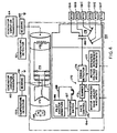
- Micro-processor based computers and other control system circuitry are contained in cabinet 118 and provide operation and control of power plant 100.
- cabinet 118 includes Westinghouse Distributed Processing Family (WDPF) equipment sold by Westinghouse Electric Corporation and can include two distributed processing units, an engineers console and a logger.
- WDPF Westinghouse Distributed Processing Family
- Such other control system circuitry would include appropriate input/output (I/O) circuitry necessary for interfacing the computer control systems with various operating equipment and condition sensors.
- An operator's cabinet 120 associated with the control cabinet 118, contains vibration monitor, electronics for UV flame detectors, a synchroscope and various push-button switches.
- a printer 122 and a protective relay panel 124 for sensing abnormal electric power system conditions are associated with the control cabinet 118.
- the present invention would be implemented in its preferred form in WDPF equipment contained in cabinet 118.
- circuits shown in Figs. 2 and 3 allow plant 100 to be separated from an external power system in trouble without shutting down gas turbine 104.
- the breaker nearest the power system load would be tripped to drop the load and let generator 102 continue to run and supply its own auxiliaries.
- the fuel demand representation is applied to a dual fuel control where the fuel demand signal is processed to produce a gas fuel demand signal for application to the gas starting and throttle valves or a liquid fuel demand signal for application to the oil throttle and pressure bypass valve or as a combination of gas and liquid fuel demand signals for application to the gas and oil valves together.
- Comparator 422 determines whether the sign of the load derivative is positive or negative. If the sign of the load derivative is negative, the output of comparator 422 is a logic high which is provided to AND gate 416. Upon receipt of logic high signals at all inputs of AND gate 416, the output will become logic high which is connected to the set input of a set/reset flipflop 424. The "Q" output of flipflop 424 enables a monostable multivibrator 426. The output of multivibrator 426 is provided to the speed reference generator 304. In the preferred embodiment, a logic high signal from vibrator 426 serves to set the speed reference signal to be representative of 3600 rpm.
- rate monitor 440 detects that the speed is changing in excess of the speed change limits a logic high output is provided to AND gate 442.
- the load signal is provided to rate monitor 444 which monitors the rate of change of the load signal.
- Monitor 444 generates a logic high output when the rate of change of the load signal exceeds the predetermined load change limits.
- the predetermined load change limits are identical to those utilized by comparators 420 and 422. When a logic high signal appears at both inputs to AND gate 442, a logic high output is provided to the set input of set/reset flipflop 446.
Claims (8)
- Ein Elektrizitätskraftwerk (100) zur Erzeugung von elektrischem Strom zur Versorgung eines elektrischen Kraftnetzes (137) mit Energie, wobei dieses Kraftwerk enthält:eine Verbrennungsturbine (104), wobei die Verbrennungsturbine durch Verbrennen von Kraftstoff in der Turbine arbeitet, wobei der Kraftstoffdurchsatz in Reaktion auf ein Steuersignal geregelt wird;einen Generator (102), der mit der Turbine (104) und dem Kraftnetz (137) verbunden ist, so daß durch den Betrieb der Turbine elektrische Energie erzeugt wird; wobei diese Turbine aufweist;ein erstes Referenzglied (314) zum Generieren eines Drehzahlsignals, das die Turbinendrehzahl wiedergibt;ein zweites Referenzglied (309) zum Generieren eines Lastsignals, das die Generatorlast wiedergibt;eine Steuerung (312) zum Generieren eines Steuersignals im Zusammenhang mit dem Unterschied zwischen dem Drehzahlsignal und dem Bezugsdrehzahlsignal; undein drittes Referenzglied (304) zum Generieren des Bezugsdrehzahlsignals, dadurch gekennzeichnet, daß das dritte Referenzglied (304) beinhalteteinen ersten Änderungswächter (440), der zum Empfang des Drehzahlsignals zur Überwachung der Änderungsgeschwindigkeit des Drehzahlsignals angeschlossen ist, und zum Generieren eines Drehzahlangabesignals, wenn die Änderungsgeschwindigkeit des Drehzahlsignals vorgegebene Drehzahländerungsgrenzen überschreitet;ein zweiter Änderungswächter (444), der zum Empfang des Lastsignals zur Überwachung der Anderungsgeschwindigkeit des Lastsignals und zum Generieren eines Lastanzeigesignals angeschlossen ist, wenn die Änderungsgeschwindigkeit des Lastsignals vorgegebene Laständerungsgrenzen überschreitet; undeinen Signalgenerator zum Generieren eines Bezugsdrehzahlsignals, das repräsentativ für die Synchrondrehzahl ist, wenn der erste und der zweite Anderungsgeschwindigkeitswächter eine Überschreitung der Änderungsgeschwindigkeitsgrenzen und der Laständerungsgrenzen anzeigen.
- Ein Kraftwerk gemäß Definition in Anspruch 1, dadurch gekennzeichnet, daß ein viertes Bezugsglied (448) zur Erzeugung eines Maximalturbinendrehzahl-Bezugssignals vorgesehen ist, das ein Maximalturbinenbezugsdrehzahlsignal und das Drehzahlsignal empfängt und das Drehzahlsignal mit dem Maximalturbinenbezugsdrehzahlsignal vergleicht, wobei das Bezugsdrehzahlsignal einen Zwischensolldrehzahlwert anzeigt, wenn die erste und zweite Anderungsgeschwindigkeitswächter (440, 444) anzeigen, daß die Drehzahlsänderungsgrenzen und die Laständerungsgrenzen überschritten wurden, und wenn das vierte Bezugsglied (448) bestimmt, daß das Drehzahlsignal das Maximalturbinendrehzahlsignal überschreitet.
- Ein Verfahren zur Erfassung eines Lastabwurfs in einer Verbrennungsturbine (104), wobei ein Drehzahlsignal, das für die Turbinendrehzahl repräsentativ ist, und ein Lastsignal, das für die Turbinenlast repräsentativ ist, vorgesehen sind, und das Verfahren durch die folgenden Schritte gekennzeichnet ist:Generieren eines Delta-Drehzahlbezugssignals;Generieren eines Delta-Lastbezugssignals;Bestimmen der Ableitung des Drehzahlsignals, wobei diese Ableitung eine Drehzahlableitung definiert;Bestimmen der Ableitung des Lastsignals, wobei diese Ableitung eine Lastableitung definiert;Vergleichen der Drehzahlableitung mit dem Delta-Drehzahlbezugssignal;Vergleichen der Lastableitung mit dem Delta-Lastbezugssignal; undAnzeigen, wenn die Drehzahlableitung das Delta-Drehzahlbezugssignal überschreitet und wenn die Lastableitung das Delta-Lastbezugssignal überschreitet.
- Ein Verfahren gemäß Anspruch 3, dadurch gekennzeichnet, daß die Drehzahlableitung bestimmt wird durch die Ableitung des Drehzahlsignals nach der Zeit.
- Ein Verfahren gemäß Anspruch 4, dadurch gekennzeichnet, daß die Lastableitung bestimmt wird durch die Ableitung des Lastsignals nach der Zeit.
- Ein Verfahren gemäß Anspruch 3, wobei die Delta-Bezugsdrehzahl und die Drehzahlableitung eine Größe und ein Vorzeichen haben, und wobei der Schritt des Vergleichens der Drehzahlableitung mit dem Delta-Bezugsdrehzahlsignal gekennzeichnet wird durch den Verlgeich der Größe und des Vorzeichens des Delta-Bezugsdrehzahlsignals mit der Größe und dem Vorzeichen der Drehzahlableitung.
- Das Verfahren gemäß Anspruch 6, wobei die Delta-Bezugslast und die Lastableitung eine Größe und ein Vorzeichen haben, und wobei der Schritt des Vergleichens der Lastableitung mit dem Delta-Bezugslastsignal gekennzeichnet wird durch den Vergleich der Größe und des Vorzeichens des Delta-Bezugslastsignals mit der Größe und dem Vorzeichen der Lastableitung.
- Das Verfahren gemäß Anspruch 3, wobei ein Maximal-Turbinendrehzahl-Bezugssignal vorgesehen ist, dadurch gekennzeichnet, daß das Drehzahlsignal mit dem Maximal-Turbinendrehzahl-Bezugssignal verglichen wird und eine Anzeige vorgesehen ist, wenn die Drehzahlableitung das Delta-Bezugsdrehzahlsignal überschreitet, wenn die Lastableitung das Delta-Bezugslastsignal überschreitet, und wenn das Drehzahlsignal das Maximal-Turbinendrehzahlsignal überschreitet.
Applications Claiming Priority (2)
| Application Number | Priority Date | Filing Date | Title |
|---|---|---|---|
| US07/607,921 US5180923A (en) | 1990-11-01 | 1990-11-01 | Method and apparatus for downline load rejection sensing in a gas turbine control system |
| US607921 | 1990-11-01 |
Publications (2)
| Publication Number | Publication Date |
|---|---|
| EP0483570A1 EP0483570A1 (de) | 1992-05-06 |
| EP0483570B1 true EP0483570B1 (de) | 1996-05-01 |
Family
ID=24434264
Family Applications (1)
| Application Number | Title | Priority Date | Filing Date |
|---|---|---|---|
| EP91117400A Expired - Lifetime EP0483570B1 (de) | 1990-11-01 | 1991-10-11 | Verfahren und Vorrichtung zur Erfassung der Beseitigung einer Abwärtslast in einem Kontrollsystem für eine Gasturbine |
Country Status (5)
| Country | Link |
|---|---|
| US (1) | US5180923A (de) |
| EP (1) | EP0483570B1 (de) |
| JP (1) | JPH0696994B2 (de) |
| CA (1) | CA2054645A1 (de) |
| DE (1) | DE69119187T2 (de) |
Cited By (1)
| Publication number | Priority date | Publication date | Assignee | Title |
|---|---|---|---|---|
| CN107210694A (zh) * | 2015-02-03 | 2017-09-26 | 西门子股份公司 | 用于监测发电设施的运行的方法和设备 |
Families Citing this family (18)
| Publication number | Priority date | Publication date | Assignee | Title |
|---|---|---|---|---|
| NO952860L (no) * | 1994-08-08 | 1996-02-09 | Compressor Controls Corp | Framgangsmåte og apparat for å hindre parameterdrift i gassturbiner |
| US5521444A (en) * | 1994-11-30 | 1996-05-28 | Honeywell Inc. | Apparatus for transferring electrical power from a stationary device to a rotating device without the use of brushes or contacts |
| US5953902A (en) * | 1995-08-03 | 1999-09-21 | Siemens Aktiengesellschaft | Control system for controlling the rotational speed of a turbine, and method for controlling the rotational speed of a turbine during load shedding |
| US5609465A (en) * | 1995-09-25 | 1997-03-11 | Compressor Controls Corporation | Method and apparatus for overspeed prevention using open-loop response |
| DE19601359A1 (de) * | 1996-01-16 | 1997-07-17 | Fraunhofer Ges Forschung | Verfahren zum Steuern eines Gleichstromantriebs |
| US5949153A (en) * | 1997-03-06 | 1999-09-07 | Consolidated Natural Gas Service Company, Inc. | Multi-engine controller |
| US6707169B2 (en) * | 2000-07-19 | 2004-03-16 | Honda Giken Kogyo Kabushiki Kaisha | Engine generator, controller, starter apparatus, and remote control system for the engine generator |
| AT413132B (de) * | 2001-08-03 | 2005-11-15 | Jenbacher Ag | Mehrzylindrige stationäre brennkraftmaschine |
| RU2298653C2 (ru) * | 2002-07-04 | 2007-05-10 | Сименс Акциенгезелльшафт | Способ регулирования частоты вращения турбины, подключенной посредством генератора к электрической сети энергоснабжения (варианты) и устройство для его осуществления (варианты) |
| DE10328932A1 (de) * | 2003-06-27 | 2005-01-13 | Alstom Technology Ltd | Verfahren und Vorrichtung zum Erfassen eines Lastabwurfes zwischen einer elektrische Energie erzeugenden Rotationsmaschine und einem zur Stromversorgung an die Rotationsmaschine angeschlossenen Versorgungsnetzwerkes |
| US7449795B2 (en) * | 2005-08-05 | 2008-11-11 | Siemens Energy, Inc. | Electric power generation system using a permanent magnet dynamoelectric machine for starting a combustion turbine and for generating uninterruptible excitation power |
| US7535684B2 (en) * | 2007-01-09 | 2009-05-19 | Honeywell International Inc. | Overspeed protection for sensorless electric drives |
| GB0816637D0 (en) * | 2008-09-12 | 2008-10-22 | Rolls Royce Plc | Blade Pitch Control |
| GB0816636D0 (en) * | 2008-09-12 | 2008-10-22 | Rolls Royce Plc | Controlling rotor overspeed |
| US8744634B2 (en) * | 2010-11-19 | 2014-06-03 | General Electric Company | Safety instrumented system (SIS) for a turbine system |
| US9771823B2 (en) * | 2014-06-26 | 2017-09-26 | General Electric Company | Power generation system control following transient grid event |
| JP6680555B2 (ja) * | 2016-02-10 | 2020-04-15 | 三菱日立パワーシステムズ株式会社 | ガスタービン制御装置、ガスタービン制御方法及びプログラム |
| CN110344945B (zh) * | 2019-07-25 | 2021-10-01 | 中国航发沈阳发动机研究所 | 一种甩负荷控制方法及系统 |
Citations (1)
| Publication number | Priority date | Publication date | Assignee | Title |
|---|---|---|---|---|
| US4470257A (en) * | 1982-04-30 | 1984-09-11 | Westinghouse Electric Corp. | Isochronous and droop speed control for a combustion turbine |
Family Cites Families (8)
| Publication number | Priority date | Publication date | Assignee | Title |
|---|---|---|---|---|
| US3601617A (en) * | 1970-05-28 | 1971-08-24 | Gen Electric | Turbine control system with early valve actuation under unbalanced conditions |
| US4019315A (en) * | 1973-06-20 | 1977-04-26 | Westinghouse Electric Corporation | Gas turbine power plant control apparatus including a temperature reset starting control system and an ignition pressure control system |
| CH589785A5 (de) * | 1974-05-31 | 1977-07-15 | Bbc Brown Boveri & Cie | |
| GB1520882A (en) * | 1974-07-24 | 1978-08-09 | Lucas Industries Ltd | Electronic fuel control for a gas turbine engine |
| US4136286A (en) * | 1977-07-05 | 1979-01-23 | Woodward Governor Company | Isolated electrical power generation system with multiple isochronous, load-sharing engine-generator units |
| JPS55104533A (en) * | 1979-02-06 | 1980-08-11 | Nissan Motor Co Ltd | Fuel control system for gas turbine |
| GB8717287D0 (en) * | 1987-07-22 | 1987-11-18 | Lucas Ind Plc | Closed loop control system |
| US5095221A (en) * | 1989-11-03 | 1992-03-10 | Westinghouse Electric Corp. | Gas turbine control system having partial hood control |
-
1990
- 1990-11-01 US US07/607,921 patent/US5180923A/en not_active Expired - Lifetime
-
1991
- 1991-10-11 DE DE69119187T patent/DE69119187T2/de not_active Expired - Fee Related
- 1991-10-11 EP EP91117400A patent/EP0483570B1/de not_active Expired - Lifetime
- 1991-10-31 CA CA002054645A patent/CA2054645A1/en not_active Abandoned
- 1991-11-01 JP JP3287646A patent/JPH0696994B2/ja not_active Expired - Lifetime
Patent Citations (1)
| Publication number | Priority date | Publication date | Assignee | Title |
|---|---|---|---|---|
| US4470257A (en) * | 1982-04-30 | 1984-09-11 | Westinghouse Electric Corp. | Isochronous and droop speed control for a combustion turbine |
Cited By (2)
| Publication number | Priority date | Publication date | Assignee | Title |
|---|---|---|---|---|
| CN107210694A (zh) * | 2015-02-03 | 2017-09-26 | 西门子股份公司 | 用于监测发电设施的运行的方法和设备 |
| CN107210694B (zh) * | 2015-02-03 | 2019-08-16 | 西门子股份公司 | 用于监测发电设施的运行的方法和设备 |
Also Published As
| Publication number | Publication date |
|---|---|
| JPH04265404A (ja) | 1992-09-21 |
| US5180923A (en) | 1993-01-19 |
| EP0483570A1 (de) | 1992-05-06 |
| DE69119187D1 (de) | 1996-06-05 |
| DE69119187T2 (de) | 1996-08-14 |
| JPH0696994B2 (ja) | 1994-11-30 |
| CA2054645A1 (en) | 1992-05-02 |
Similar Documents
| Publication | Publication Date | Title |
|---|---|---|
| EP0483570B1 (de) | Verfahren und Vorrichtung zur Erfassung der Beseitigung einer Abwärtslast in einem Kontrollsystem für eine Gasturbine | |
| US5252860A (en) | Gas turbine control system having maximum instantaneous load-pickup limiter | |
| EP0429840B1 (de) | Steuervorrichtung einer Gasturbine mit optimiertem Zündzeitpunkt | |
| US5095221A (en) | Gas turbine control system having partial hood control | |
| US4031407A (en) | System and method employing a digital computer with improved programmed operation for automatically synchronizing a gas turbine or other electric power plant generator with a power system | |
| US4536126A (en) | System and method employing a digital computer for automatically synchronizing a gas turbine or other electric power plant generator with a power system | |
| US5321308A (en) | Control method and apparatus for a turbine generator | |
| US4283634A (en) | System and method for monitoring and controlling operation of industrial gas turbine apparatus and gas turbine electric power plants preferably with a digital computer control system | |
| EP0501152B1 (de) | Einrichtung zur Zündungsdiagnose in einer Verbrennungsturbine | |
| US7045913B2 (en) | Microturbine engine system | |
| US3978659A (en) | Bumpless transfer in shifting control command between the primary and backup control systems of a gas turbine power plant | |
| EP0432570B1 (de) | Regelsystem für eine Gasturbine mit einem Aufnahmebegrenzer der maximalen unmittelbaren Leistung | |
| US4107542A (en) | Time delayed relay sequencer and alarm reset for a gas turbine local maintenance controller | |
| Coyle | Protective Relaying of Emergency and Standby Generators | |
| Aguirre | MAIN CONSIDERATIONS IN THE PROTECTION SYSTEM DESIGN FOR A GEOTHERMAL POWER PLANT | |
| Reading et al. | The Application of a Large Induction Generator to a Fluid Catalytic Cracking Power Recovery Train | |
| ILYUSHIN et al. | DN YAROSH, Yu. G. FEDOROV System Operator of the UPS | |
| JPH04303103A (ja) | タービン制御方法および装置 | |
| YAROSH et al. | PV ILYUSHIN | |
| Power Generation Committee | Minimum Recommended Protection, Interlocking and Control for Fossil Fuel Unit-Connected Steam Station I. Overall Protection | |
| Chapallaz et al. | Operation and Control | |
| Jayme et al. | CONTROL SYSTEM RETROFIT FOR FIAT TG20 GAS TURBINE POWER UNITS |
Legal Events
| Date | Code | Title | Description |
|---|---|---|---|
| PUAI | Public reference made under article 153(3) epc to a published international application that has entered the european phase |
Free format text: ORIGINAL CODE: 0009012 |
|
| AK | Designated contracting states |
Kind code of ref document: A1 Designated state(s): CH DE FR GB IT LI |
|
| 17P | Request for examination filed |
Effective date: 19920914 |
|
| 17Q | First examination report despatched |
Effective date: 19941222 |
|
| GRAH | Despatch of communication of intention to grant a patent |
Free format text: ORIGINAL CODE: EPIDOS IGRA |
|
| GRAA | (expected) grant |
Free format text: ORIGINAL CODE: 0009210 |
|
| PGFP | Annual fee paid to national office [announced via postgrant information from national office to epo] |
Ref country code: FR Payment date: 19960418 Year of fee payment: 6 |
|
| AK | Designated contracting states |
Kind code of ref document: B1 Designated state(s): CH DE FR GB IT LI |
|
| ET | Fr: translation filed | ||
| REG | Reference to a national code |
Ref country code: CH Ref legal event code: NV Representative=s name: A. BRAUN, BRAUN, HERITIER, ESCHMANN AG PATENTANWAE |
|
| PGFP | Annual fee paid to national office [announced via postgrant information from national office to epo] |
Ref country code: DE Payment date: 19960531 Year of fee payment: 6 |
|
| REF | Corresponds to: |
Ref document number: 69119187 Country of ref document: DE Date of ref document: 19960605 |
|
| ITF | It: translation for a ep patent filed |
Owner name: MODIANO & ASSOCIATI S.R.L. |
|
| PGFP | Annual fee paid to national office [announced via postgrant information from national office to epo] |
Ref country code: GB Payment date: 19960919 Year of fee payment: 6 |
|
| PGFP | Annual fee paid to national office [announced via postgrant information from national office to epo] |
Ref country code: CH Payment date: 19961211 Year of fee payment: 6 |
|
| PLBE | No opposition filed within time limit |
Free format text: ORIGINAL CODE: 0009261 |
|
| STAA | Information on the status of an ep patent application or granted ep patent |
Free format text: STATUS: NO OPPOSITION FILED WITHIN TIME LIMIT |
|
| 26N | No opposition filed | ||
| PG25 | Lapsed in a contracting state [announced via postgrant information from national office to epo] |
Ref country code: GB Free format text: LAPSE BECAUSE OF NON-PAYMENT OF DUE FEES Effective date: 19971011 |
|
| PG25 | Lapsed in a contracting state [announced via postgrant information from national office to epo] |
Ref country code: LI Free format text: LAPSE BECAUSE OF NON-PAYMENT OF DUE FEES Effective date: 19971031 Ref country code: CH Free format text: LAPSE BECAUSE OF NON-PAYMENT OF DUE FEES Effective date: 19971031 Ref country code: FR Free format text: THE PATENT HAS BEEN ANNULLED BY A DECISION OF A NATIONAL AUTHORITY Effective date: 19971031 |
|
| GBPC | Gb: european patent ceased through non-payment of renewal fee |
Effective date: 19971011 |
|
| REG | Reference to a national code |
Ref country code: CH Ref legal event code: PL |
|
| PG25 | Lapsed in a contracting state [announced via postgrant information from national office to epo] |
Ref country code: DE Free format text: LAPSE BECAUSE OF NON-PAYMENT OF DUE FEES Effective date: 19980701 |
|
| REG | Reference to a national code |
Ref country code: FR Ref legal event code: ST |
|
| PGFP | Annual fee paid to national office [announced via postgrant information from national office to epo] |
Ref country code: IT Payment date: 20101027 Year of fee payment: 20 |