EP0483570B1 - Method and apparatus for downline load rejection sensing in a gas turbine control system - Google Patents
Method and apparatus for downline load rejection sensing in a gas turbine control system Download PDFInfo
- Publication number
- EP0483570B1 EP0483570B1 EP91117400A EP91117400A EP0483570B1 EP 0483570 B1 EP0483570 B1 EP 0483570B1 EP 91117400 A EP91117400 A EP 91117400A EP 91117400 A EP91117400 A EP 91117400A EP 0483570 B1 EP0483570 B1 EP 0483570B1
- Authority
- EP
- European Patent Office
- Prior art keywords
- speed
- signal
- load
- derivative
- turbine
- Prior art date
- Legal status (The legal status is an assumption and is not a legal conclusion. Google has not performed a legal analysis and makes no representation as to the accuracy of the status listed.)
- Expired - Lifetime
Links
Images


Classifications
-
- H—ELECTRICITY
- H02—GENERATION; CONVERSION OR DISTRIBUTION OF ELECTRIC POWER
- H02J—CIRCUIT ARRANGEMENTS OR SYSTEMS FOR SUPPLYING OR DISTRIBUTING ELECTRIC POWER; SYSTEMS FOR STORING ELECTRIC ENERGY
- H02J3/00—Circuit arrangements for ac mains or ac distribution networks
- H02J3/38—Arrangements for parallely feeding a single network by two or more generators, converters or transformers
- H02J3/40—Synchronising a generator for connection to a network or to another generator
Definitions
- the present invention relates generally to the field of control systems for controlling fuel flow in combustion turbine power plants and more particularly to an electric power plant according to the preamble of claim 1, as for example disclosed in US-A - 4 470 257. Furthermore, the present invention relates to a method for controlling fuel flow during a condition of downline load rejection. Although the present invention may find particular utility in the field of gas turbine electric power plants, and will be described in relation to such equipment, the invention can also be applied to combustion turbines having other uses.
- Micro-processor based computers and other control system circuitry are contained in cabinet 118 and provide operation and control of power plant 100.
- cabinet 118 includes Westinghouse Distributed Processing Family (WDPF) equipment sold by Westinghouse Electric Corporation and can include two distributed processing units, an engineers console and a logger.
- WDPF Westinghouse Distributed Processing Family
- Such other control system circuitry would include appropriate input/output (I/O) circuitry necessary for interfacing the computer control systems with various operating equipment and condition sensors.
- An operator's cabinet 120 associated with the control cabinet 118, contains vibration monitor, electronics for UV flame detectors, a synchroscope and various push-button switches.
- a printer 122 and a protective relay panel 124 for sensing abnormal electric power system conditions are associated with the control cabinet 118.
- the present invention would be implemented in its preferred form in WDPF equipment contained in cabinet 118.
- circuits shown in Figs. 2 and 3 allow plant 100 to be separated from an external power system in trouble without shutting down gas turbine 104.
- the breaker nearest the power system load would be tripped to drop the load and let generator 102 continue to run and supply its own auxiliaries.
- the fuel demand representation is applied to a dual fuel control where the fuel demand signal is processed to produce a gas fuel demand signal for application to the gas starting and throttle valves or a liquid fuel demand signal for application to the oil throttle and pressure bypass valve or as a combination of gas and liquid fuel demand signals for application to the gas and oil valves together.
- Comparator 422 determines whether the sign of the load derivative is positive or negative. If the sign of the load derivative is negative, the output of comparator 422 is a logic high which is provided to AND gate 416. Upon receipt of logic high signals at all inputs of AND gate 416, the output will become logic high which is connected to the set input of a set/reset flipflop 424. The "Q" output of flipflop 424 enables a monostable multivibrator 426. The output of multivibrator 426 is provided to the speed reference generator 304. In the preferred embodiment, a logic high signal from vibrator 426 serves to set the speed reference signal to be representative of 3600 rpm.
- rate monitor 440 detects that the speed is changing in excess of the speed change limits a logic high output is provided to AND gate 442.
- the load signal is provided to rate monitor 444 which monitors the rate of change of the load signal.
- Monitor 444 generates a logic high output when the rate of change of the load signal exceeds the predetermined load change limits.
- the predetermined load change limits are identical to those utilized by comparators 420 and 422. When a logic high signal appears at both inputs to AND gate 442, a logic high output is provided to the set input of set/reset flipflop 446.
Description
- The present invention relates generally to the field of control systems for controlling fuel flow in combustion turbine power plants and more particularly to an electric power plant according to the preamble of claim 1, as for example disclosed in US-A - 4 470 257. Furthermore, the present invention relates to a method for controlling fuel flow during a condition of downline load rejection. Although the present invention may find particular utility in the field of gas turbine electric power plants, and will be described in relation to such equipment, the invention can also be applied to combustion turbines having other uses.
- In the operation of gas turbines, particularly in electric power plants, various kinds of control systems have been employed from relay-pneumatic type systems, to analog type electronic controls, to digital controls, and more recently to computer based software controls. For example, US-A-4 296 600 discloses an electric power plant comprising a rate monitor which is connected to receive the load signal for monitoring the rate of change of the load signal and for generating a load indication signal when the rate of change of the load exceeds a predetermined load change limit. U.S. Patent No. 4,308,463 - Giras et al., assigned to the assignee of the present invention, lists several others of such prior systems. That patent in particular discloses a digital computer based control system for use with gas turbine electric power plants. It will be noted that the Giras et al. patent is one of a family of patents all of which are cross referenced therein.
- Subsequent to the Giras et al. patent, other control systems have been introduced by Westinghouse Electric Corporation of Pittsburgh, Pennsylvania under the designations POWERLOGIC and POWERLOGIC II. Similar to the Giras et al. patent these control systems are used to control gas turbine electric power plants. However, such control systems are primarily micro-processor based computer systems, i.e. the turbine control systems are implemented in software, whereas prior control systems were implemented in electrical and electronic hardware. All modes of turbine-generator operation are controlled including control of fuel flow after the attainment of full load. Loss of full load presents interesting control system problems in relation to fuel flow control.
- When load rejection occurs in a combustion turbine-generator arrangement, the initial problem is to control fuel flow in a manner which limits turbine overspeed to a value less than the turbine trip point. If turbine speed exceeds the turbine trip point, fuel flow ceases and a flame out will occur. If load rejection is caused by the opening of the generator circuit breaker, a condition which can be readily detected in relation to the state change of breaker auxiliary contacts, appropriate procedures have been provided in previous combustion turbine control systems to hold the turbine speed set point to synchronous speed for the control of fuel flow. Since the turbine is accelerating due to a loss of load, actual turbine speed will be above the turbine speed set point resulting in a closing of the fuel throttle valve by the control system.
- A fuel problem can occur in previous procedures for controlling fuel flow in a generator breaker based load rejection condition. The problem stems from the use of a proportional, integral, differential (PID) controller. Since a PID controller is primarily a high gain proportional control, the greater the difference between actual turbine speed and the turbine speed set point, the further the closure of the fuel throttle that will occur. If the speed difference is great enough, flame out can occur. Prior procedures have been developed to prevent such a flame out condition from occurring in a generator breaker based load rejection situation. Unfortunately, load rejection in a gas turbine/generator arrangement has another form, namely, downline load rejection. Since downline load rejection is not as readily detectable as generator breaker based load rejection, a flame out situation due to turbine speed exceeding the turbine trip point is significantly more probable.
- When downline load rejection occurs, two significant events take place. First, the generator breaker remains closed, which in previous control systems allows the speed reference to remain set to the speed equivalent of full turbine load versus synchronous speed. If it is assumed that synchronous speed, i.e., the speed desired for connection of the generator to an electrical power grid, is 3600 RPM and that the turbine generator has a 4% droop governor, i.e., 100% generator power is equivalent to 104% turbine speed, the speed equivalent of full load is 3744 RPM. Second, actual turbine spead drops to approximately 3600 RPM at the instant of load rejection while the speed reference remains at 3744 RPM. The result of these events is that the fuel throttle controller sensing the speed difference between actual turbine speed and the speed reference will cause the fuel throttle valve to open until actual turbine speed exceeds the speed reference, i.e., 3744 RPM. In such a situation, it is more probable that actual speed will exceed the turbine speed trip point.
- It is the principal object of the present invention to provide a turbine-generator control scheme which will avoid tripping of the plant as a result of downline load rejection and minimize the occurrence of flame out conditions.
- With this object in view, the present invention resides in an electric power plant for generating electric power and for providing such power to an electric power grid , said power plant including:
- a combustion turbine , the combustion turbine being operative in response to the combustion of fuel in the turbine wherein the flow of fuel is regulated in response to a control signal;
- a generator , connected to the turbine and to the power grid , so that electric power is produced when the turbine is operating; said turbine having
- a first reference member for generating a speed signal reflective of turbine speed;
- a second reference member for generating a load signal reflective of the load on the generator;
- a controller for generating the control signal in relation to the difference between the speed signal and a speed reference signal; and
- a third reference member for generating the speed reference signal, characterized in that the third reference member includes
- a first rate monitor , connected to receive the speed signal for monitoring the rate of change of the speed signal and for generating a speed indication signal when the rate of change of the speed signal exceeds predetermined speed change limits;
- a second rate monitor , connected to receive the load signal for monitoring the rate of change of the load signal and for generating a load indication signal when the rate of change of the load signal exceeds predetermined load change limits; and
- a signal generator for generating a speed reference signal which is representative of synchronous speed when the first and second rate monitors are indicating that the speed change limits and the load change limits have been exceeded.
- The invention will become more readily apparent from the following description of a preferred embodiment thereof shown, by way of example only, in the accompanying drawings, in which:
- Fig. 1 is a top plan view of a gas turbine power plant arranged to operate in accordance with the principles of the present invention;
- Figs. 2 and 3 are respective electrical systems usable in the operation of the gas turbine power plant of Fig. 1;
- Fig. 4 is a schematic view of a rotating rectifier exciter and a generator employed in the gas turbine power plant of Fig. 1;
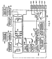
- Fig. 5 shows a schematic diagram of a control loop which may be employed in operating the computer control system of Fig. 1; and
- Figs. 6 and 7 are schematic diagrams of alternative embodiments for detecting downline load rejection in accordance with the present invention.
- There is shown in Fig. 1 a gas turbine
electric power plant 100 which includesAC generator 102 driven by combustion orgas turbine 104. In the embodiment described herein,gas turbine 104 is preferably the W 501D5 type manufactured by Westinghouse Electric Corporation. - A typical use of
power plant 100 is where continuous power generation is desired and the exhaust heat fromgas turbine 104 is desired for other purposes such as feedwater heating, boilers, oreconomizers. Power plant 100 can be located relatively close to load centers, i.e. population centers or manufacturing sites, as indicated by system requirements without the need for a cooling water supply thereby advantageously producing a savings in transmission facilities. Further,power plant 100 is capable of being relatively unattended and automatically operated from a remote location. - Community acceptance of
power plant 100 is enhanced by the use of inlet andexhaust silencers exhaust ductworks - In order to gain an appreciation of the size of the power plant described herein, the foundation for
plant 100 is approximately 106 feet long if a control station is provided for a single plant unit. The foundation length can be increased as indicated by thereference character 116 to provide for a master control station. A master control station would be warranted if additional plant units, grouped withplant 100, are to have common control. Although the present invention can be utilized in a master control setting for multiple power plants, for simplicity, the invention is described herein in relation to only a single turbine generator. - Micro-processor based computers and other control system circuitry are contained in
cabinet 118 and provide operation and control ofpower plant 100. In the preferred embodiment,cabinet 118 includes Westinghouse Distributed Processing Family (WDPF) equipment sold by Westinghouse Electric Corporation and can include two distributed processing units, an engineers console and a logger. Such other control system circuitry would include appropriate input/output (I/O) circuitry necessary for interfacing the computer control systems with various operating equipment and condition sensors. An operator'scabinet 120, associated with thecontrol cabinet 118, contains vibration monitor, electronics for UV flame detectors, a synchroscope and various push-button switches. Aprinter 122 and aprotective relay panel 124 for sensing abnormal electric power system conditions are associated with thecontrol cabinet 118. The present invention would be implemented in its preferred form in WDPF equipment contained incabinet 118. - Startup or cranking power for the
plant 100 is provided by astarting engine 126 which in the preferred embodiment is an AC motor unit. Startingengine 126 is mounted on an auxiliary bedplate and coupled to the drive shaft ofgas turbine 104 through astarting gear unit 128. During the initial startup period,AC motor 128 operates through aturning gear 130 and startinggear 132 to drive the gas turbine. Whenturbine 104 reaches approximately 20 percent of rated speed, ignition takes place.AC motor 128 continues to operate untilturbine 104 reaches sustaining speed.AC motor 128 can be operated for longer periods if turbine disc cavity temperature is excessive, in order to avoid thermally induced shaft bowing. - A
motor control center 134 is also mounted on the auxiliary bedplate and it includes motor starters and other devices to provide for operation of the various auxiliary equipment items associated with theplant 100. Electrical breakers formotor control center 134 are preferably front mounted. Various signals from sensor or contact elements associated withmotor control center 134 and with other devices mounted on the auxiliary bedplate are transmitted for use in the control system. - A
plant battery 135 is disposed adjacent to one end of the auxiliary bedplate or skid. A battery charger, described in relation to Fig. 1, is connected to themotor control center 134 through a breaker (not shown).Battery 135 can be any heavy duty control battery such as the EHGS-17 EXIDE rated at 125 volts, 60 cells. In any event,battery 135 should be capable of supplying adequate power for emergency lighting, auxiliary motor loads, computer supply voltages and other control power for one hour following shutdown of theplant 100. - One possible internal electrical power system for use with
plant 100 is shown generally in Fig. 2. Onceplant 100 is in operation, power generated bygenerator 102 is transmitted to the power system throughgenerator breaker 136, through 13.8KV bus 137 to a main transformer (not shown) andline breaker 138. Auxiliary power for theplant 100 is obtained from the internal power system through anauxiliary breaker 139 and an auxiliary power 480 volt bus 140. Thegenerator breaker 136 serves as a synchronizing and protective disconnect device for theplant 100. - If a suitable 480 volt source is not available in the internal power system, an
auxiliary power transformer 141 can be provided as shown in Fig. 3. Adisconnect switch 142 is connected betweentransformer 141 and the station 13.8 KVbus 137. The arrangement as shown in Fig. 3 can provide for so-called black plant startup operation. With this arrangement,gas turbine 104 may be started at any time, since the auxiliaries may be supplied from eithergenerator 102 or the internal power system, whichever is energized. In a black start, i.e. a dead system,gas turbine 104 may be started at any time for availability as a so-called spinning standby power source, even though the external power system, to whichplant 100 is connected, is not ready to accept power fromgenerator 102. Further, the circuits shown in Figs. 2 and 3 allowplant 100 to be separated from an external power system in trouble without shutting downgas turbine 104. The breaker nearest the power system load would be tripped to drop the load and letgenerator 102 continue to run and supply its own auxiliaries. - An additional advantage of the scheme shown in Fig. 3 is the protection provided if the connection to the power system is vulnerable to a permanent fault between
plant 100 and the next breaker in the system. In such asituation line breaker 138 would be the clearing breaker in case of such a fault and the auxiliary system would remain energized bygenerator 102 which would allow an orderly shutdown of thegas turbine 104 or continued operation as standby. - The arrangement of Fig. 3 is preferable if
gas turbine 104 is programmed to start during a system low voltage or decaying frequency situation. During such events, automatic startup could bringturbine 104 up to speed,close generator breaker 136 and supply power to the auxiliary load. The turbine-generator unit would then be running and would be immediately available when desired. The arrangement of Fig. 3 can also be utilized if an under-frequency or under-voltage signal is to be used to separate thegas turbine 104 from the system. - A
switchgear pad 143 is included for 15 KVswitchgear generator breaker 136. Theauxiliary power transformer 141 and disconnectswitch 142 are also disposed onswitchgear pad 143 if they are selected for use by the user.Excitation switchgear 150 associated with the generator excitation system is also included on theswitchgear pad 143. As will be described in greater detail hereinafter, the I/O circuitry ofcabinet 118 accepts signals from certain sensor or contact elements associated with various switchgear pad devices. - A pressure switch and gauge cabinet 152 is also included on the auxiliary bedplate. Cabinet 152 contains the pressure switches, gauges, regulators and other miscellaneous elements needed for gas turbine operation.
- Although not specifically shown, it should be understood that
plant 100 also incorporates a turbine high pressure cooling system and a radiation-type air-to-oil cooler for lubrication oil cooling. Such devices can be of any known design. -
Generator 102, includingbrushless exciter 154, is schematically illustrated in greater detail in Fig. 4. The rotating elements ofgenerator 102 andexciter 154 are supported by a pair ofbearings generator vibration transducers 162 and 164 are coupled tobearings - Resistance temperature detectors (RTD) 181 A-F, embedded in the stator winding, are installed to measure the air inlet and discharge temperatures and the bearing oil drain temperatures as indicated in Fig. 4. Signals from the temperature sensors and
vibration transducers 162 and 164 are transmitted to the control system, i.e.cabinet 118. - In the operation of the
exciter 154, a permanentmagnet field member 165 is rotated to induce voltage in apilot exciter armature 166 which is coupled to a stationaryAC exciter field 168 through a voltage regulator (not shown). Voltage is thereby induced in anAC exciter armature 172 formed on the exciter rotating element and it is applied across diodes mounted with fuses on a diode wheel 174 to energize arotating field element 176 of thegenerator 102. Generator voltage is induced in a stationary armature winding 178 which supplies current to the power system through agenerator breaker 136 when theplant 100 is synchronized and on the line. Atransformer 180 supplies a feedback signal for theregulator 170 to control the excitation level of theexciter field 168. The signal fromtransformer 180 is also used as the generator megawatt signal, a control signal supplied tocabinet 118. In relation to the present invention, the generator megawatt signal is used as an indication of the generator load onturbine 104. - Generally,
exciter 154 operates without the use of brushes, slip rings, and external connections to the generator field. Brush wear, carbon dust, brush maintenance requirements and brush replacement are thereby eliminated. - In the preferred embodiment, all of the exciter parts are supported by
generator 102. The generator rotor can be installed and withdrawn without requiring removal of the exciter rotor from the generator shaft. - Consider now the control system utilized in controlling
plant 100.Power plant 100 is operated under the control of an integrated turbine-generator computer based control system. The plant control system embraces elements disposed incontrol cabinet 118, the pressure switch and gauge cabinet 152 and other elements included in theelectric power plant 100 of Fig. 1. The control system is characterized with centralized system packaging. Thus, thecontrol cabinet 118 shown in Fig. 1 houses an entire speed/load control package, an automatic plant sequence package, and a systems monitoring package. As a further benefit to the plant operator, turbine and generator operating functions are in the preferred embodiment included on a single operator's panel in conformity with the integrated turbine-generator plant control provided by the control system. - Under automatic
control power plant 100 can be operated under local operator control or it can be unattended and operated by remote supervisory control. Further, theplant 100 is started from rest, accelerated under accurate and efficient control to synchronous speed preferably in a normal fixed time period to achieve in the general case extended time between turbine repairs, synchronized manually or automatically with the power system and loaded under preferred ramp control to a preselectable constant or temperature limit controlled load level thereby providing better power plant management. - The starting sequence generally embraces starting and operating the starting engine to accelerate the
gas turbine 104 from low speed, stopping the turning gear, igniting the fuel in the combustion system at about 20% rated speed, accelerating the gas turbine to about 60% rated speed and stopping the starting engine, accelerating thegas turbine 104 to synchronous speed, and loading the power aftergenerator breaker 136 closure. During shutdown, fuel flow is stopped and thegas turbine 104 undergoes a deceleration coastdown. The turning gear is started to drive the turbine rotating element during the cooling off period. - A control loop arrangement shown in Fig. 2 provides a representation of the preferred general control looping embodied in the control system and applicable in a wide variety of other applications of the invention. Protection, sequencing, more detailed control functioning and other aspects of the control system operation are subsequently considered more fully herein. In the drawings, SAMA standard function symbols are employed.
- The control loop arrangement comprises an arrangement of blocks of process control loops for use in operating the gas
turbine power plant 100. No delineation is made in Fig. 2 between hardware and software elements since many aspects of the control philosophy can be implemented in hard or soft form. - Generally, a feedforward characterization is preferably used to determine a representation of fuel demand needed to satisfy speed requirements. Measured process variables including turbine speed, ambient temperature and pressure, the controlled load variable or the plant megawatts, combustor shell pressure and turbine exhaust temperature are employed to limit, calibrate or control the fuel demand so that apparatus design limits are not exceeded. The characterization of the feedforward speed fuel demand, a start ramp limit fuel demand and a maximum exhaust temperature limit fuel demand are preferably nonlinear in accordance with the nonlinear characteristics of the gas turbine to achieve more accurate, efficient, available and reliable gas turbine apparatus operation. The control arrangement has capability for maintaining cycle temperature, gas turbine apparatus speed, acceleration rate during startup, loading rate and compressor surge margin.
- The fuel demand in the control arrangement provides position control for turbine gas or liquid fuel valves, 263 and 274. Further, the control arrangement can provide for simultaneous burning of gas and liquid fuel and it can provide for automatic bumpless transfer from one fuel to the other when required. The subject of bumpless plant transfer between different fuels and the plant operation associated therewith is known and has been disclosed in U.S. pat. No. 3,919,623, incorporated herein by reference.
- In the combination of plural control loop functions shown in Fig. 5, a low
fuel demand selector 316 is employed to limit fuel demand by selecting from various fuel limit representations generated by each control loop. These limit representations are generated respectively by speed control 303, startramp control 305, maximumexhaust temperature control 306,maximum megawatt control 307 and maximum instantaneousload pickup limiter 308. - During startup and after ignition, start
ramp control 305 provides a closed loop fuel demand to accelerateturbine 104 to approximately 80% rated speed. From 80% speed up to and through synchronization, speed control 303controls turbine 104 to maintain a constant acceleration and desired speed during synchronization. - After synchronization of
generator 102, turbine speed is regulated by the power system frequency if the power system is large. Consequently, after synchronization speed control 303 regulates fuel flow by ramping the speed reference signal, generated at 304 by any known technique, in order to cause a ramping of the megawatt output ofgenerator 102. The present invention, more particularly described in relation to Figs. 6 and 7, manipulates the speed reference in situations where downline load rejection has been detected to regulate fuel flow. - In the preferred embodiment, turbine speed is controlled during normal operation by proportional, integral, differential (PID)
controller 312. A megawatt feedback signal representative of the megawatt output ofgenerator 102 is generated at 309 by any known technique, for example via the signal generated bytransformer 180, and is provided to switch 310.Switch 310 provides the megawatt feedback signal to a negative input ofcontroller 312 whenevergenerator breaker control 311 indicates that the generator breaker has been closed. A signal representative of turbine speed is generated byspeed sensor 314, by any known technique, and is provided to another negative input ofcontroller 312. The speed reference signal is provided to the positive input ofcontroller 312. - Since
controller 312 will require its inputs to sum zero and since the speed signal fromsensor 314 is essentially constant at synchronization, the speed reference signal will be balanced by the megawatt signal such that the output ofcontroller 312 will be representative of a ramping of the speed reference signal to pick up load. - As the turbine load, i.e. generator megawatt output, is increased,
control loops exhaust temperature control 307 will eventually control fuel flow toturbine 104 to the maximum allowed temperature. - At low ambient temperatures,
maximum megawatt control 308 will become low selected beforemaximum temperature control 307 becomes effective. - At the output of the low
fuel demand selector 316, the fuel demand representation is applied to a dual fuel control where the fuel demand signal is processed to produce a gas fuel demand signal for application to the gas starting and throttle valves or a liquid fuel demand signal for application to the oil throttle and pressure bypass valve or as a combination of gas and liquid fuel demand signals for application to the gas and oil valves together. - The control arrangement generally protects gas turbine apparatus against factors including too high loading rates, too high speed excursions during load transients, too high speed at generator breaker close, too high fuel flow which may result in overload too low fuel flow which may result in combustor system outfires during all defined modes of operation, compressor surge, and excessive turbine inlet exhaust and blade over-temperature. Further, the control arrangement meets all requirements set forth in the NEMA publication "Gas Turbine Governors", SM32-1960 relative to system stability and transient response and adjustment capability. As augmented by the embodiments of the present invention illustrated in Figs. 6 and 7,
control arrangement 302 also promotes efficient operation of the gas turbine during downline load rejection conditions. - The apparatus and method for detecting downline load rejection, i.e. load rejection while
generator breaker 136 remains closed, is more particularly shown in Figures 6 and 7. As indicated previously, the method and apparatus of the present invention is preferably implemented in programming contained in cabinet 118 (Fig. 1). Generally, the present invention serves to detect downline load rejection conditions despitegenerator breaker 136 being closed and serves to fix the speed reference signal at a suitable level until turbine overspeed is controlled. - As shown in Figure 6, the turbine speed signal generated at 314 (Fig. 6) is provided to a first
derivative generator 410.Generator 410 determines the derivative of the speed signal which derivative thereby defines a speed derivative. In the preferred embodiment such speed derivative is reflective of the derivative of the speed signal with respect to time. The speed derivative is thereafter provided tocomparator 412 which compares the magnitude of the speed derivative to the magnitude of a preselected delta speed reference. If the magnitude of the speed derivative is greater than the magnitude of the preselected delta speed reference the speed derivative is thereafter provided tocomparator 414.Comparator 414 determines whether the sign of the speed derivative is positive. If the sign of the speed derivative is positive a logic high signal is provided to ANDgate 416. At all other times, the output ofcomparator 414 remains low. - Concurrently with the processing of the speed signal, a load signal representative of the turbine load is provided to a second
derivative generator 418. In the preferred embodiment this load signal is representative of the load ongenerator 102 and is provided bytransformer 180. In the preferred embodiment this load signal is converted to a digital signal prior to application toderivative generator 418.Generator 418 determines the derivative of the load signal, which in the preferred embodiment is with respect to time. The derivative of the load signal defines a load derivative. The load derivative is thereafter provided tocomparator 420.Comparator 420 compares the magnitude of the load derivative to the magnitude of a preselected delta load reference. If the magnitude of the load derivative exceeds the magnitude of the preselected delta load reference, the load derivative is provided tocomparator 422.Comparator 422 determines whether the sign of the load derivative is positive or negative. If the sign of the load derivative is negative, the output ofcomparator 422 is a logic high which is provided to ANDgate 416. Upon receipt of logic high signals at all inputs of ANDgate 416, the output will become logic high which is connected to the set input of a set/reset flipflop 424. The "Q" output offlipflop 424 enables amonostable multivibrator 426. The output ofmultivibrator 426 is provided to thespeed reference generator 304. In the preferred embodiment, a logic high signal fromvibrator 426 serves to set the speed reference signal to be representative of 3600 rpm. - As will be appreciated from the above, a logic high output from AND
gate 416 is representative of turbine speed increasing in excess of a predetermined rate and generator load decreasing in excess of a predetermined rate. In a preferred embodiment wherein a W501D5 combustion turbine-generator arrangement, the preselected delta speed reference is approximately equal to 100 rpm per second and the preselected delta load reference is approximately equal to minus 200 megawatts per second. - There will also be noted that the speed signal is provided to
comparator 428.Comparator 428 compares the speed of the turbine to a preselected value which is slightly above synchronous speed. In the preferred embodiment, this preselected value is approximately equal to 3672 rpm. If turbine speed is greater than the preselected speed value a logic high signal is provided bycomparator 428 to ANDgate 430. The other input of ANDgate 430 is connected to the "Q" output offlipflop 424. As will be appreciated from this arrangement, once a downline load rejection has been detected, a logic high output will appear atflipflop 424. Since turbine speed will generally be above synchronous speed, i.e. 104 percent of rated speed or 3744 rpm, a logic high output will also appear atcomparator 428 which in turn results in a logic high output appearing at ANDgate 430. The provision of a logic high output from ANDgate 430 to speedreference 304 serves to set the speed reference to slightly below synchronous speed until the actual speed returns to a value just below the reference speed utilized bycomparator 428. In the preferred embodiment, a logic high output from ANDgate 430 serves to set the speed reference at approximately 3200 rpm. Once the actual speed drops below that value utilized bycomparator 428, a logic low output will appear from ANDgate 430 and the remaining logic high output frommultivibrator 426 will serve to set the speed reference at synchronous speed or 3600 rpm. - An especially preferred embodiment of the present invention is depicted in Figure 7. As shown in Figure 7, the speed signal from
speed sensor 314 is provided to rate monitor 440. Rate monitor 440 monitors the rate at which speed is changing and whether such change is positive or negative, i.e. increasing or decreasing. Such a rate monitor is presently known and has been implemented in WDPF Software and is available as a building block for software design. Although such rate monitor is known, its use as described in relation to the present invention is not known. A logic high output fromrate monitor 440 indicates that the speed is changing in a fashion which exceeds predetermined speed change limits. In the preferred embodiment, the speed change limits are identical to those utilized in relation tocomparators rate monitor 440 detects that the speed is changing in excess of the speed change limits a logic high output is provided to ANDgate 442. The load signal is provided to rate monitor 444 which monitors the rate of change of the load signal.Monitor 444 generates a logic high output when the rate of change of the load signal exceeds the predetermined load change limits. In the preferred embodiment, the predetermined load change limits are identical to those utilized bycomparators gate 442, a logic high output is provided to the set input of set/reset flipflop 446. - The speed signal is also provided to
comparator 448 which determines whether speed is in excess of a preselected speed. The preselected speed utilized bycomparator 448 is identical to that utilized bycomparator 428. If the speed is in excess of the preselected speed a logic high output is presented to ANDgate 450. The "Q" output offlipflop 446 is also connected to ANDgate 450 andmonostable multivibrator 452. - Similar to the operation described in relation to Figure 6, if the magnitude and sign of the load and speed signals exceeds the magnitude and sign of the predetermined speed change limits and the predetermined load change limits, a logic high output is presented to flipflop 446 which in turn results in a logic high signal being presented to the input of AND
gate 450 andmultivibrator 452. Similar to ANDgate 430, ANDgate 450 holds the speed reference to a value which is slightly less than synchronous speed, i.e. approximately 3200 rpm. Once turbine speed drops below the value utilized bycomparator 448,multivibrator 452 serves to set the speed reference at synchronous speed, namely 3600 rpm. - While the invention has been described and illustrated with reference to specific embodiments, those skilled in the art will recognize that modification and variations may be made without departing from the principles of the invention as described herein above and set forth in the following claims.


Claims (8)
- An electric power plant (100) for generating electric power and for providing such power to an electric power grid (137), said power plant including:a combustion turbine (104), the combustion turbine being operative in response to the combustion of fuel in the turbine wherein the flow of fuel is regulated in response to a control signal;a generator (102), connected to the turbine (104) and to the power grid (137), so that electric power is produced when the turbine is operating; said turbine havinga first reference member (314) for generating a speed signal reflective of turbine speed;a second reference member (309) for generating a load signal reflective of the load on the generator;a controller (312) for generating the control signal in relation to the difference between the speed signal and a speed reference signal; anda third reference member (304) for generating the speed reference signal, characterized in that the third reference member (304) includesa first rate monitor (440), connected to receive the speed signal for monitoring the rate of change of the speed signal and for generating a speed indication signal when the rate of change of the speed signal exceeds predetermined speed change limits;a second rate monitor (444), connected to receive the load signal for monitoring the rate of change of the load signal and for generating a load indication signal when the rate of change of the load signal exceeds predetermined load change limits; anda signal generator for generating a speed reference signal which is representative of synchronous speed when the first and second rate monitors are indicating that the speed change limits and the load change limits have been exceeded.
- A power plant as defined in claim 1, characterized by a fourth reference member (448) for generating a maximum turbine speed reference signal is provided and connected to receive the maximum turbine speed reference signal and the speed signal for comparing the speed signal to the maximum turbine speed reference signal, the speed reference signal being representative of an intermediate set point speed when the first and second rate monitors (440, 444) are indicating that the speed change limits and the load change limits have been exceeded and when the fourth reference member (448) determines that the speed signal exceeds the maximum turbine speed signal.
- A method for detecting load rejection in a combustion turbine (104), wherein a speed signal representative of the turbine speed and a load signal representative of the turbine load are provided, the method characterized the steps of:generating a delta speed reference signal;generating a delta load reference signal;determining the derivative of the speed signal, such derivative defining a speed derivative;determining the derivative of the load signal, such derivative defining a load derivative;comparing the speed derivative to the delta speed reference signal;comparing the load derivative to the delta load reference signal; andindicating when the speed derivative exceeds the delta speed reference signal and when the load derivative exceeds the delta load reference signal.
- A method according to claim 3, characterized in that the speed derivative is determined by taking the derivative of the speed signal with respect to time.
- A method according to claim 4, characterized in that the load derivative is determined by taking the derivative of the load signal with respect to time.
- A method according to claim 3, wherein the delta speed reference and the speed derivative have a magnitude and a sign and wherein the step of comparing the speed derivative to the delta speed reference signal is characterized by comparing the magnitude and sign of the delta speed reference signal with the magnitude and sign of the speed derivative.
- The method according to claim 6, wherein the delta load reference and the load derivative have a magnitude and a sign and wherein the step of comparing the load derivative to the delta load reference signal is characterized by comparing the magnitude and sign of the delta load signal with the magnitude and sign of the load derivative.
- The method according to claim 3, wherein a maximum turbine speed reference signal is provided, characterized in that the speed signal is compared to the maximum turbine speed reference signal and an indication is provided of when the speed derivative exceeds the delta speed reference signal, when the load derivative exceeds the delta load reference signal and when the speed signal exceeds the maximum turbine speed signal.
Applications Claiming Priority (2)
| Application Number | Priority Date | Filing Date | Title |
|---|---|---|---|
| US07/607,921 US5180923A (en) | 1990-11-01 | 1990-11-01 | Method and apparatus for downline load rejection sensing in a gas turbine control system |
| US607921 | 1990-11-01 |
Publications (2)
| Publication Number | Publication Date |
|---|---|
| EP0483570A1 EP0483570A1 (en) | 1992-05-06 |
| EP0483570B1 true EP0483570B1 (en) | 1996-05-01 |
Family
ID=24434264
Family Applications (1)
| Application Number | Title | Priority Date | Filing Date |
|---|---|---|---|
| EP91117400A Expired - Lifetime EP0483570B1 (en) | 1990-11-01 | 1991-10-11 | Method and apparatus for downline load rejection sensing in a gas turbine control system |
Country Status (5)
| Country | Link |
|---|---|
| US (1) | US5180923A (en) |
| EP (1) | EP0483570B1 (en) |
| JP (1) | JPH0696994B2 (en) |
| CA (1) | CA2054645A1 (en) |
| DE (1) | DE69119187T2 (en) |
Cited By (1)
| Publication number | Priority date | Publication date | Assignee | Title |
|---|---|---|---|---|
| CN107210694A (en) * | 2015-02-03 | 2017-09-26 | 西门子股份公司 | For the method and apparatus for the operation for monitoring power generating equipment |
Families Citing this family (18)
| Publication number | Priority date | Publication date | Assignee | Title |
|---|---|---|---|---|
| NO952860L (en) * | 1994-08-08 | 1996-02-09 | Compressor Controls Corp | Method and apparatus for preventing parameter drift in gas turbines |
| US5521444A (en) * | 1994-11-30 | 1996-05-28 | Honeywell Inc. | Apparatus for transferring electrical power from a stationary device to a rotating device without the use of brushes or contacts |
| US5953902A (en) * | 1995-08-03 | 1999-09-21 | Siemens Aktiengesellschaft | Control system for controlling the rotational speed of a turbine, and method for controlling the rotational speed of a turbine during load shedding |
| US5609465A (en) * | 1995-09-25 | 1997-03-11 | Compressor Controls Corporation | Method and apparatus for overspeed prevention using open-loop response |
| DE19601359A1 (en) * | 1996-01-16 | 1997-07-17 | Fraunhofer Ges Forschung | Method for controlling a DC drive |
| US5949153A (en) * | 1997-03-06 | 1999-09-07 | Consolidated Natural Gas Service Company, Inc. | Multi-engine controller |
| US6707169B2 (en) * | 2000-07-19 | 2004-03-16 | Honda Giken Kogyo Kabushiki Kaisha | Engine generator, controller, starter apparatus, and remote control system for the engine generator |
| AT413132B (en) * | 2001-08-03 | 2005-11-15 | Jenbacher Ag | MULTI-CYLINDER STATIONARY INTERNAL COMBUSTION ENGINE |
| RU2298653C2 (en) * | 2002-07-04 | 2007-05-10 | Сименс Акциенгезелльшафт | Method to control speed of turbine connected by generator to power supply system (versions) and device for implementing the method (versions) |
| DE10328932A1 (en) * | 2003-06-27 | 2005-01-13 | Alstom Technology Ltd | Method and device for detecting a load shedding between a rotary electric machine generating electrical energy and a supply network connected to the power supply to the rotary machine |
| US7449795B2 (en) * | 2005-08-05 | 2008-11-11 | Siemens Energy, Inc. | Electric power generation system using a permanent magnet dynamoelectric machine for starting a combustion turbine and for generating uninterruptible excitation power |
| US7535684B2 (en) * | 2007-01-09 | 2009-05-19 | Honeywell International Inc. | Overspeed protection for sensorless electric drives |
| GB0816637D0 (en) * | 2008-09-12 | 2008-10-22 | Rolls Royce Plc | Blade Pitch Control |
| GB0816636D0 (en) * | 2008-09-12 | 2008-10-22 | Rolls Royce Plc | Controlling rotor overspeed |
| US8744634B2 (en) * | 2010-11-19 | 2014-06-03 | General Electric Company | Safety instrumented system (SIS) for a turbine system |
| US9771823B2 (en) * | 2014-06-26 | 2017-09-26 | General Electric Company | Power generation system control following transient grid event |
| JP6680555B2 (en) * | 2016-02-10 | 2020-04-15 | 三菱日立パワーシステムズ株式会社 | Gas turbine control device, gas turbine control method and program |
| CN110344945B (en) * | 2019-07-25 | 2021-10-01 | 中国航发沈阳发动机研究所 | Load shedding control method and system |
Citations (1)
| Publication number | Priority date | Publication date | Assignee | Title |
|---|---|---|---|---|
| US4470257A (en) * | 1982-04-30 | 1984-09-11 | Westinghouse Electric Corp. | Isochronous and droop speed control for a combustion turbine |
Family Cites Families (8)
| Publication number | Priority date | Publication date | Assignee | Title |
|---|---|---|---|---|
| US3601617A (en) * | 1970-05-28 | 1971-08-24 | Gen Electric | Turbine control system with early valve actuation under unbalanced conditions |
| US4019315A (en) * | 1973-06-20 | 1977-04-26 | Westinghouse Electric Corporation | Gas turbine power plant control apparatus including a temperature reset starting control system and an ignition pressure control system |
| CH589785A5 (en) * | 1974-05-31 | 1977-07-15 | Bbc Brown Boveri & Cie | |
| GB1520882A (en) * | 1974-07-24 | 1978-08-09 | Lucas Industries Ltd | Electronic fuel control for a gas turbine engine |
| US4136286A (en) * | 1977-07-05 | 1979-01-23 | Woodward Governor Company | Isolated electrical power generation system with multiple isochronous, load-sharing engine-generator units |
| JPS55104533A (en) * | 1979-02-06 | 1980-08-11 | Nissan Motor Co Ltd | Fuel control system for gas turbine |
| GB8717287D0 (en) * | 1987-07-22 | 1987-11-18 | Lucas Ind Plc | Closed loop control system |
| US5095221A (en) * | 1989-11-03 | 1992-03-10 | Westinghouse Electric Corp. | Gas turbine control system having partial hood control |
-
1990
- 1990-11-01 US US07/607,921 patent/US5180923A/en not_active Expired - Lifetime
-
1991
- 1991-10-11 EP EP91117400A patent/EP0483570B1/en not_active Expired - Lifetime
- 1991-10-11 DE DE69119187T patent/DE69119187T2/en not_active Expired - Fee Related
- 1991-10-31 CA CA002054645A patent/CA2054645A1/en not_active Abandoned
- 1991-11-01 JP JP3287646A patent/JPH0696994B2/en not_active Expired - Lifetime
Patent Citations (1)
| Publication number | Priority date | Publication date | Assignee | Title |
|---|---|---|---|---|
| US4470257A (en) * | 1982-04-30 | 1984-09-11 | Westinghouse Electric Corp. | Isochronous and droop speed control for a combustion turbine |
Cited By (2)
| Publication number | Priority date | Publication date | Assignee | Title |
|---|---|---|---|---|
| CN107210694A (en) * | 2015-02-03 | 2017-09-26 | 西门子股份公司 | For the method and apparatus for the operation for monitoring power generating equipment |
| CN107210694B (en) * | 2015-02-03 | 2019-08-16 | 西门子股份公司 | Method and apparatus for monitoring the operation of power generating equipment |
Also Published As
| Publication number | Publication date |
|---|---|
| EP0483570A1 (en) | 1992-05-06 |
| DE69119187D1 (en) | 1996-06-05 |
| CA2054645A1 (en) | 1992-05-02 |
| DE69119187T2 (en) | 1996-08-14 |
| US5180923A (en) | 1993-01-19 |
| JPH04265404A (en) | 1992-09-21 |
| JPH0696994B2 (en) | 1994-11-30 |
Similar Documents
| Publication | Publication Date | Title |
|---|---|---|
| EP0483570B1 (en) | Method and apparatus for downline load rejection sensing in a gas turbine control system | |
| US5252860A (en) | Gas turbine control system having maximum instantaneous load-pickup limiter | |
| EP0429840B1 (en) | Gas turbine control system having optimized ignition air flow control | |
| US5095221A (en) | Gas turbine control system having partial hood control | |
| US4031407A (en) | System and method employing a digital computer with improved programmed operation for automatically synchronizing a gas turbine or other electric power plant generator with a power system | |
| US4536126A (en) | System and method employing a digital computer for automatically synchronizing a gas turbine or other electric power plant generator with a power system | |
| US5321308A (en) | Control method and apparatus for a turbine generator | |
| US4283634A (en) | System and method for monitoring and controlling operation of industrial gas turbine apparatus and gas turbine electric power plants preferably with a digital computer control system | |
| EP0501152B1 (en) | Apparatus for ignition diagnosis in a combustion turbine | |
| US7045913B2 (en) | Microturbine engine system | |
| US3978659A (en) | Bumpless transfer in shifting control command between the primary and backup control systems of a gas turbine power plant | |
| EP0432570B1 (en) | Gas turbine control system having maximum instantaneous load pickup limiter | |
| US4107542A (en) | Time delayed relay sequencer and alarm reset for a gas turbine local maintenance controller | |
| Coyle | Protective Relaying of Emergency and Standby Generators | |
| Aguirre | MAIN CONSIDERATIONS IN THE PROTECTION SYSTEM DESIGN FOR A GEOTHERMAL POWER PLANT | |
| Reading et al. | The Application of a Large Induction Generator to a Fluid Catalytic Cracking Power Recovery Train | |
| ILYUSHIN et al. | DN YAROSH, Yu. G. FEDOROV System Operator of the UPS | |
| JPH04303103A (en) | Turbine control method and device | |
| YAROSH et al. | PV ILYUSHIN | |
| Power Generation Committee | Minimum Recommended Protection, Interlocking and Control for Fossil Fuel Unit-Connected Steam Station I. Overall Protection | |
| Chapallaz et al. | Operation and Control | |
| Jayme et al. | CONTROL SYSTEM RETROFIT FOR FIAT TG20 GAS TURBINE POWER UNITS |
Legal Events
| Date | Code | Title | Description |
|---|---|---|---|
| PUAI | Public reference made under article 153(3) epc to a published international application that has entered the european phase |
Free format text: ORIGINAL CODE: 0009012 |
|
| AK | Designated contracting states |
Kind code of ref document: A1 Designated state(s): CH DE FR GB IT LI |
|
| 17P | Request for examination filed |
Effective date: 19920914 |
|
| 17Q | First examination report despatched |
Effective date: 19941222 |
|
| GRAH | Despatch of communication of intention to grant a patent |
Free format text: ORIGINAL CODE: EPIDOS IGRA |
|
| GRAA | (expected) grant |
Free format text: ORIGINAL CODE: 0009210 |
|
| PGFP | Annual fee paid to national office [announced via postgrant information from national office to epo] |
Ref country code: FR Payment date: 19960418 Year of fee payment: 6 |
|
| AK | Designated contracting states |
Kind code of ref document: B1 Designated state(s): CH DE FR GB IT LI |
|
| ET | Fr: translation filed | ||
| REG | Reference to a national code |
Ref country code: CH Ref legal event code: NV Representative=s name: A. BRAUN, BRAUN, HERITIER, ESCHMANN AG PATENTANWAE |
|
| PGFP | Annual fee paid to national office [announced via postgrant information from national office to epo] |
Ref country code: DE Payment date: 19960531 Year of fee payment: 6 |
|
| REF | Corresponds to: |
Ref document number: 69119187 Country of ref document: DE Date of ref document: 19960605 |
|
| ITF | It: translation for a ep patent filed |
Owner name: MODIANO & ASSOCIATI S.R.L. |
|
| PGFP | Annual fee paid to national office [announced via postgrant information from national office to epo] |
Ref country code: GB Payment date: 19960919 Year of fee payment: 6 |
|
| PGFP | Annual fee paid to national office [announced via postgrant information from national office to epo] |
Ref country code: CH Payment date: 19961211 Year of fee payment: 6 |
|
| PLBE | No opposition filed within time limit |
Free format text: ORIGINAL CODE: 0009261 |
|
| STAA | Information on the status of an ep patent application or granted ep patent |
Free format text: STATUS: NO OPPOSITION FILED WITHIN TIME LIMIT |
|
| 26N | No opposition filed | ||
| PG25 | Lapsed in a contracting state [announced via postgrant information from national office to epo] |
Ref country code: GB Free format text: LAPSE BECAUSE OF NON-PAYMENT OF DUE FEES Effective date: 19971011 |
|
| PG25 | Lapsed in a contracting state [announced via postgrant information from national office to epo] |
Ref country code: LI Free format text: LAPSE BECAUSE OF NON-PAYMENT OF DUE FEES Effective date: 19971031 Ref country code: CH Free format text: LAPSE BECAUSE OF NON-PAYMENT OF DUE FEES Effective date: 19971031 Ref country code: FR Free format text: THE PATENT HAS BEEN ANNULLED BY A DECISION OF A NATIONAL AUTHORITY Effective date: 19971031 |
|
| GBPC | Gb: european patent ceased through non-payment of renewal fee |
Effective date: 19971011 |
|
| REG | Reference to a national code |
Ref country code: CH Ref legal event code: PL |
|
| PG25 | Lapsed in a contracting state [announced via postgrant information from national office to epo] |
Ref country code: DE Free format text: LAPSE BECAUSE OF NON-PAYMENT OF DUE FEES Effective date: 19980701 |
|
| REG | Reference to a national code |
Ref country code: FR Ref legal event code: ST |
|
| PGFP | Annual fee paid to national office [announced via postgrant information from national office to epo] |
Ref country code: IT Payment date: 20101027 Year of fee payment: 20 |