EP0482299B1 - Verbesserte Plotterschreibgerätvorrichtung - Google Patents
Verbesserte Plotterschreibgerätvorrichtung Download PDFInfo
- Publication number
- EP0482299B1 EP0482299B1 EP91112088A EP91112088A EP0482299B1 EP 0482299 B1 EP0482299 B1 EP 0482299B1 EP 91112088 A EP91112088 A EP 91112088A EP 91112088 A EP91112088 A EP 91112088A EP 0482299 B1 EP0482299 B1 EP 0482299B1
- Authority
- EP
- European Patent Office
- Prior art keywords
- assembly
- ink cartridge
- plotter
- nib
- adapter
- Prior art date
- Legal status (The legal status is an assumption and is not a legal conclusion. Google has not performed a legal analysis and makes no representation as to the accuracy of the status listed.)
- Expired - Lifetime
Links
- 230000007704 transition Effects 0.000 claims abstract description 13
- 239000004033 plastic Substances 0.000 claims description 41
- 229910052751 metal Inorganic materials 0.000 claims description 6
- 239000002184 metal Substances 0.000 claims description 6
- 239000000463 material Substances 0.000 claims description 4
- 230000000712 assembly Effects 0.000 abstract description 7
- 238000000429 assembly Methods 0.000 abstract description 7
- 239000007788 liquid Substances 0.000 description 10
- 238000010276 construction Methods 0.000 description 7
- 230000013011 mating Effects 0.000 description 5
- 239000004743 Polypropylene Substances 0.000 description 3
- 238000005452 bending Methods 0.000 description 3
- 239000000835 fiber Substances 0.000 description 3
- -1 polypropylene Polymers 0.000 description 3
- 229920001155 polypropylene Polymers 0.000 description 3
- 230000000295 complement effect Effects 0.000 description 2
- 239000000919 ceramic Substances 0.000 description 1
- 239000012530 fluid Substances 0.000 description 1
- 238000003780 insertion Methods 0.000 description 1
- 230000037431 insertion Effects 0.000 description 1
- 238000000465 moulding Methods 0.000 description 1
- 238000007789 sealing Methods 0.000 description 1
- 239000002689 soil Substances 0.000 description 1
- 230000008961 swelling Effects 0.000 description 1
- UONOETXJSWQNOL-UHFFFAOYSA-N tungsten carbide Chemical compound [W+]#[C-] UONOETXJSWQNOL-UHFFFAOYSA-N 0.000 description 1
Images
Classifications
-
- B—PERFORMING OPERATIONS; TRANSPORTING
- B43—WRITING OR DRAWING IMPLEMENTS; BUREAU ACCESSORIES
- B43L—ARTICLES FOR WRITING OR DRAWING UPON; WRITING OR DRAWING AIDS; ACCESSORIES FOR WRITING OR DRAWING
- B43L13/00—Drawing instruments, or writing or drawing appliances or accessories not otherwise provided for
- B43L13/02—Draughting machines or drawing devices for keeping parallelism
- B43L13/022—Draughting machines or drawing devices for keeping parallelism automatic
- B43L13/024—Drawing heads therefor
-
- B—PERFORMING OPERATIONS; TRANSPORTING
- B26—HAND CUTTING TOOLS; CUTTING; SEVERING
- B26F—PERFORATING; PUNCHING; CUTTING-OUT; STAMPING-OUT; SEVERING BY MEANS OTHER THAN CUTTING
- B26F1/00—Perforating; Punching; Cutting-out; Stamping-out; Apparatus therefor
- B26F1/38—Cutting-out; Stamping-out
- B26F1/3806—Cutting-out; Stamping-out wherein relative movements of tool head and work during cutting have a component tangential to the work surface
-
- B—PERFORMING OPERATIONS; TRANSPORTING
- B26—HAND CUTTING TOOLS; CUTTING; SEVERING
- B26D—CUTTING; DETAILS COMMON TO MACHINES FOR PERFORATING, PUNCHING, CUTTING-OUT, STAMPING-OUT OR SEVERING
- B26D7/00—Details of apparatus for cutting, cutting-out, stamping-out, punching, perforating, or severing by means other than cutting
- B26D7/26—Means for mounting or adjusting the cutting member; Means for adjusting the stroke of the cutting member
- B26D2007/2678—Means for mounting or adjusting the cutting member; Means for adjusting the stroke of the cutting member for cutting pens mounting in a cutting plotter
Definitions
- a plotter pen assembly that is adapted for a friction fit directly within a Calcomp® plotter, is illustrated by GUNDERSON, ET AL., (U.S.-A-4,540,993).
- the pen body essentially comprises a nib portion in combination with an ink reservoir portion, with a barrel and a guide ridge or stop shoulder that is friction fit within a pen holder arm of the plotter to accurately locate the pen with respect to a drawing surface.
- the wide popularity of graphic plotters has suggested the advantage of a plotter pen assembly which, through different surrounding adapters, might fit in a wide variety of graphic plotting devices.
- the plotter-pen assembly should be without regard to the specific pen assembly geometry required by a given pen holder, or whether the nib element is configured as a liquid ink tubular stylus; a fiber tip; a roller ball; or a ball-point.
- Model 64C One prior art DPP® plotter pen assembly sold by Koh-I-Noor Rapidograph, Inc., of Bloomsbury, New Jersey, assignee of the present invention; is the Model 64C style pen assembly, which is also illustrated in FIG. 1.
- the Model 64C is a two piece assembly specifically designed for use with an adapter to fit certain Calcomp® model plotters, and without an adapter to fit other Calcomp® model plotters.
- the present invention involves defining certain important dimensions within a plotter pen assembly, so that associated adapter rings will permit use of the same pen assembly in a wide variety of plotter devices.
- the prior art generally has required very specifically shaped plotter pens for each plotter model made by a particular manufacturer, so that no wide use for a single plotter pen assembly has been possible.
- the prior art generally recognizes use of an adapter assembly for mounting a plotter pen assembly against a first seating shoulder.
- the present invention uniquely permits a single liquid ink nib assembly and a single ink cartridge assembly, for example, to cooperate as a single plotter pen assembly, that has alternative contact means, with a set of different adapters.
- the present invention also permits either single piece, or multiple piece plotter pen assemblies and either active or refillable plotter pen assemblies to be configured for use with the same set of adapters.
- the adapters in turn, each have a particular configuration for a friction (or other) mounting within the plotting head of a particular plotting machine.
- a first object of the present invention to provide a novel two-piece plotter pen assembly (by combining a novel ink cartridge assembly with a conventional nib assembly) that will permit a large number of alternative mounting options, through adapters, for the drawing heads of various plotting machine manufacturers.
- a second object of the present invention is to provide a novel single-piece, two-piece or multiple-piece plotter pen assembly that will permit a large number of alternative pen types and mounting options, through a common set of adapters, for the drawing heads of various plotting machine manufacturers.
- a preferred embodiment consists of two piece assembly, wherein a liquid ink nib assembly of hard plastic holds a tubular stylus for liquid ink, and a separate soft plastic, non-refillable ink cartridge is joined thereto.
- the nib assembly portion in various embodiments of the present invention may be itself conventional. Nib assemblies of such structure have been used in the prior art.
- a nib assembly essentially comprises a hard plastic cylindrical element wherein a nib element fits within a transition cylindrical section, and a mounting cylindrical section.
- the nib element may be a tubular stylus for liquid ink that is made from metal, plastic, tungsten carbide or ceramic or the nib element may be a ball point, a roller ball, a fiber tip, or of other known types.
- the mounting cylindrical section conventionally may include a rearward surface configuration that is particularly shaped to be press fit, within the open end at the front of a surrounding, soft plastic ink cartridge assembly.
- This nib assembly of a preferred embodiment has certain dimensions and certain tolerances, as known in the prior art.
- a first seating shoulder defined between the transition circular section and the mounting circular section is spaced axially (with respect to the leading edge of the nib element) without regard to either the dimensions of a separate ink cartridge assembly, or any other form of writing fluid reservoir that feeds forwardly, to the nib-element.
- the second seating shoulder is defined axially rearwardly of the first seating shoulder
- the second shoulder is formed as part of a soft plastic ink cartridge assembly, and is not part of a hand plastic nib assembly. However, because that ink cartridge assembly is press fit from the rear onto the back of the nib assembly, to an exact axial mounting position, the second seating shoulder becomes accurately spaced axially, with, respect to the leading edge of the nib element. In other embodiments, the second seating shoulder also is accurately spaced axially with respect to the leading edge of a nib element.
- the second seating shoulder is very particularly designed to cooperate with adapter structure, so as to perform a secure mounting with those adapters that cannot seat against the first, or preferred, seating shoulder, in all embodiments.
- any adapter may be configured to securely engage either the first seating shoulder or the second seating shoulder. While seating against the first seating shoulder is considered preferred, the present invention uniquely defines both first and second seating shoulders that alternatively may be used. Further, in either alternative there is a secure and accurate location of the leading edge of the plotter pen nib element with respect to a reference drawing surface, when the plotter pen assembly is used according to its intended purpose, in a graphics plotting machine.
- a nib assembly for a metal tubular stylus has a prior art construction, wherein a first seating shoulder is located .394 inches or 10 mm, axially spaced from the leading edge of a tubular nib.
- This first shoulder is defined by an annulus and an adjacent chamfered surface, on the lower edge of a mounting cylindrical surface thereof, that has a diameter of approximately 0.245 inches, or 6.22 mm.
- the transition cylindrical section below the first shoulder conventionally has a diameter of .155 inches or 3.94 mm.
- a nib assembly with such dimensions per se is a prior art geometry.
- the 64C style DPP® pen assembly sold by Koh-I-Noor Rapidograph, Inc. has such dimensions.
- the 64C pen assembly can be used with an adapter, that seats against the first shoulder, to define a combination that fits the Calcomp® 102x, 104x, series of graphics plotter machines.
- the preferred embodiment of the present pen assembly combines such a conventional, hard plastic nib assembly with a novel soft plastic ink cartridge assembly, so as define also a second seating dimension, that also is controlled with a defined tolerance dimension above the leading edge of the nib element.
- the second seating dimension preferably is axially spaced 2.358 inches or 59.89 mm a from the leading edge of a nib element such as a metal tubular liquid ink stylus, when a two-piece pen assembly is defined.
- the second seating shoulder is a transverse annular surface defined between a maximum ink cartridge diameter of 0.450 inches, or 11.43 mm, and the maximum diameter of an immediately adjacent external thread of the ink cartridge assembly.
- Prior art specifications for direct mount ink cartridge assemblies such as the DPP® Model 64C, have required coarse external mounting threads and narrow shoulders. Such specifications are considered incapable of performing the function of a secure second seating shoulder, when used with an adapter. For example, within the 64C, the annular transverse seating surface located between the rear portion of a coarse thread and the ink cartridge maximum diameter was too narrow and too easily deformable and would not resist bending moments around the pen assembly axis.
- the present invention provides a wider annular second seating shoulder and a shallower thread configuration that together cooperate to permit a secure mounting of a pen assembly in various adapters of a second type.
- a shallow external thread upon a minimized ink cartridge shaft diameter, or equivalent pen assembly body structure, a larger annular second seating shoulder is available for contact with a hard plastic transverse annulus of various adapter rings.
- the transverse annulus of soft plastic on the ink cartridge subassembly is sufficiently large, so that it will not deform against a complementary, hard plastic transverse surface of the surrounding adapter.
- the second shoulders is spaced axially from the tubular nib leading edge at a reference dimension of 2.358 inches, or 59.89 nun, instead of only 2.08 inches, or 52.8 mm, as in the Model 64C.
- This longer dimension has been found to permit the greatest number of possible plotter adapter fits, where a second mounting location is needed.
- the ink cartridge mounting shaft outer diameter is slightly smaller at a maximum reference dimension of .352 inches, or 8.94 mm, instead of a maximum reference dimension of 0.36 inches or 9.1 mm, in the Model 64C.
- the ink cartridge maximum diameter also is smaller, at a reference dimension of 0.45 inches or 11.43 mm, instead of a dimension of a dimension of .54 inches, or 13.7 mm in the Model 64C. These relationships permit the pen assembly to fit a greater number of adapters and, therefore, a greater number of plotting machines.
- the outer diameter maximum of an ink cartridge mounting shaft in the preferred embodiment also is configured for a certain diametrical clearance fit, preferably 0.005 inches, within an axial guideway of any associated adapters. This clearance will preclude axial bending movements, and consequent ink leakage.
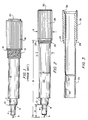
- FIG. 1 is a side elevational view of a prior art form of pen assembly, and in particular the Model 64C style, plotter pen assembly noted hereinbefore.
- This non-refillable plotter pen assembly comprises essentially two major subassemblies.
- a hard plastic nib subassembly comprises a mounting cylindrical section, 2, a transition cylindrical section, 4, and a nib element, 6, wherein a first seating shoulder annulus, 8, is surrounded by a chamfered surface between the transition cylindrical section and the mounting cylindrical section.
- a soft plastic ink cartridge subassembly comprising a mounting shaft section, 12, to accept the nib assembly by a press fit, an ink cartridge maximum diameter in a reservoir section, 16, and a means to mount the ink cartridge into a plotter head.
- Coarse threads, 14, are the mounting means illustrated at FIG. 1.
- the mounting thread specification is 7/16-20UNF.
- the ink cartridge assembly further comprises a button, 20, which doses an open end after filling. Between the maximum cylindrical section, which may be knurled, as shown, and the ink cartridge mounting shaft diameter, 12, is shown a transverse shoulder, 18.
- the Model 64C style plotter pen assembly shown is used with an adapter, in order to fit within the 102x, 104x series of Calcomp® plotters.
- the Model 64C style pen assembly also may mount directly. Internal threads on the arm of a plotter head in the Calcomp® 96x, 97x, family of graphical plotters may engage directly with the external mounting threads, 14. However, in that application there is significant plotter structure to engage a large area of the coarse, soil plastic threads, 14, so as to supply adequate rigidity.
- the adapter typically used with the plotter pen assembly of FIG. 1 will produce an external configuration equivalent to that for a unitary pen, as illustrated in GUNDERSON, ET AL. (U.S.-A-4,540,993).
- FIG. 2 is a side elevational view of a preferred plotter pen assembly of two-piece construction, according to the present invention. Since the nib assembly is fully equivalent to that illustrated as a subassembly in FIG. 1, the same numerals have been used to identify the same parts.
- the non-refillable ink cartridge assembly according to the preferred embodiment comprises a mounting shaft, 22, and a maximum diameter section which also may be knurled, to define a reservoir, 26. Between the reservoir or maximum diameter and the ink cartridge mounting shaft is a fine threaded mounting means, 24. In the preferred embodiment, the thread is 0.393 x 36 TPI, which is uniquely suited to the present application because it is shallow, with a small difference between the major and minor diameters of the thread.
- a second mounting shoulder, 28, is defined by an annulus between the outer diameter of the fine thread, 24, and the outer diameter of the ink cartridge reservoir section, 26.
- the ink cartridge reservoir is also shown to have an open end dosed by a button, 30, but may be dosed by any equivalent means. While a non-refillable reservoir thereby is implied, a refillable reservoir also may be employed.
- the preferred assembly of FIG. 2 has a hard plastic nib assembly as shown in the prior art design of FIG. 1, but with a soft plastic ink cartridge assembly, 22, that is significantly elongated, and with different geometrical relationships.
- a first axial distance, A is identified.
- A is set at 10 mm or 0.394 inches.
- a second axial distance, B preferably is 59.89 mm or 2.358 inches. Both of these dimensions are referenced with respect to the leading edge of a nib element, that is shown to be a liquid ink tubular stylus, 6.
- Such a preferred embodiment now will be illustrated as to function, with respect to two alternate forms of adapters.
- the preferred ink cartridge, 22, is molded from a soft plastic, such as polypropylene, and a preferred ink volume is between 2.0 cc and 3.0 cc.
- the nib assembly as in the prior art, may be color coded as to the point size, and is comprised of a hard plastic, or metal. Therefore, the first dimension A defines a first seating contact with a first type of adapter that is between a first shoulder annulus, 8, and a hard plastic mating surface on an adapter.
- the second dimension B defines a second seating contact that is between a second seating annulus, 28, and a hard plastic or metal mating surface of a second type of adapter.
- the fine thread, 24, and the dimensions between the ink cartridge mounting shaft, 22, and the ink cartridge maximum diameter, 26, also are particularly chosen to help define a rigid, second mounting against the second shoulder, 28.
- the ink cartridge mounting shaft outer diameter preferably is 0.352 inches, as a maximum, or 8.94 mm, as shown by reference C.
- the ink cartridge maximum outer diameter, reference E is preferably 0.45 inches, or 11.43 mm in the vicinity of the shoulder, 28.
- the relative difference between diameters C and E is important and a maximum value to outer shaft diameter, C, also is an important fit constraint.
- the maximum diameters, C and E, with a 0.393 x 36 TPI thread, will create a larger annulus for the second seating shoulder, 28, than is created by the geometry of FIG. 1 at the shoulder, 18.
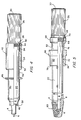
- FIG. 3 illustrates, in vertical cross-section, the basic interior structure of a novel ink cartridge portion of the combination shown in the preferred embodiment of FIG. 2.
- the ink cartridge shown in FIG. 3 is of unitary soft plastic construction, preferably polypropylene and is of the non-refillable type.
- An axial stop, 32 is spaced 0.875 inches ( ⁇ .003) inside the ink cartridge forward end.
- the forward end also has a tapered inner diameter, 34, that is adapted to tightly engage over the rear end of the mounting cylindrical section, 2, of the nib assembly, as in the prior art.
- External threads are formed by molding at 24, and a wall section, 26, in the vicinity of the major diameter is relatively thick, to act as a rigidifying element for the second seating shoulder, 28.
- An open rear end, 36 conventionally is dosed by a button or other form, of closure, 30, as shown in FIG. 2.
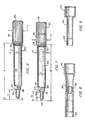
- FIG. 4 illustrates the preferred plotter pen assembly of FIG. 2 in combination with an adapter of the first type, wherein the axial mounting is between complementary surfaces on an adapter body, and the first seating shoulder annulus, 8.
- the adapter body, 40 is shown in partial cross-section to comprise an axial, reflective-surface cylinder section, 42, and is intended for use with a Calcomp® 102x, 104x type of graphics plotter.
- the adapter of FIG. 4 also has an external configuration equivalent to the pen body, shown in the patent to GUNDERSON, discussed hereinbefore
- the adapter internal threads, 44 are significantly longer than the mating external threads, 24, of the plotter pen assembly.
- a needed guide ridge, 46 is generated on the outside of the adapter body.
- Axial mounting is accomplished by contact between an axial stop, 48, against the first seating shoulder annulus, 8. A further contact also may be made against the immediately adjacent chamfered surface, 10.
- the axial stop, 48 preferably is defined by an inner surface of a transverse wall, at the leading edge of the adapter, 58.
- the rear end of the adapter, 50 is shown spaced axially ahead of the second seating shoulder, 28, so as not to interfere with the first seating.
- there is an axial guideway, 52, within the adapter which is defined to leave approximately 0.13 mm (0.005 inches) of diametrical clearance, around the outer diameter of an ink cartridge mounting shaft diameter, 22.
- an ink cartridge diameter of this type can swell approximately 0.05 mm (0.002 inches) upon assembly, and that a diametrical clearance of 0.13 mm (0.005 inches) will act as a secure, yet non-binding, interface between the adapter and the outside of the cartridge mounting shaft portion.
- the reflective-surface cylindrical portion, 42 also preferably has a heavy wall thickness, 54, in the vicinity of the threads, 44, to guarantee rigidity as the adapter is screwed tightly upon the soft plastic external threads, 24.
- FIG. 5 A second type of adapter for the pen assembly of FIG. 2 is shown in FIG. 5, wherein the adapter, 60, again is shown in partial cross-section.
- Adapter bodies of the second type are needed for applications where the first seating shoulder is not available.
- the adapter shown in FIG. 5 is useful with an Hitachi 675 model graphics plotter wherein the adapter leading edge, 78, is spaced approximately 1.457 inches above the leading edge of the tubular nib, 6.
- the adapter of FIG. 5 has an inner cylindrical section, 62, an internal thread, 64, a guide ridge, 66, and an outer cylindrical section, 68, particularly configured for a mounting within an Hitachi 675 plotter head pen holder, for example.
- FIG. 5 also illustrates the combination of plotter pen assembly, adapter assembly and cap, as would be combined just before mounting in a graphics plotter head. While the rear end of a second type adapter. 70, tightly abuts against the second annular seating shoulder, 28, of the plotter pen assembly, further axial bending movement rigidity is supplied by an axial guideway, 72, that is located within a relatively thick wall section, 74 of the adapter.
- the Hitachi 675 adapter illustrated in FIG. 5 also has a thin wall section, 76, but that section does not affect the rigidity which comes from a tight engagement at the second seating shoulder, 28, and an axial guideway engagement between the outer diameter of the ink cartridge mounting shaft, 22, and the inner diameter of the adapter axial guideway, 72.
- the preferred diametrical dearance between the axial guideway and the outer diameter of the ink cartridge mounting shaft, 22, is on the order of 0.13 mm (0.005 inches), and may be as large as 0.25 mm (0.010 inches), in order to accommodate a radial distension, or swelling, of the cartridge upon an axial mounting into the adapter.
- Figure 6 is a side elevation view of a second plotter pen assembly embodiment, of one-piece construction according to the present invention.
- the illustrated nib element is of the roller ball type, and the entire nib assembly is mounted as part of a single piece of support structure.
- this is a one-piece pen type of plotter pen assembly, where the ink reservoir, the plotter pen body assembly and the nib assembly are assembled as a single or unitary device.
- the nib element typically is a fiber tip, a ball point or a roller ball, as illustrated.
- Such plotter pen assemblies typically are nonrefillable.
- the one piece assembly shown as a second embodiment in FIG. 6 comprises a central body shaft portion, 82 and a maximum diameter upper body potion, 96 which may be knurled, as illustrated.
- the body essentially defines a reservoir.
- the thread of this mounting means is 0.393 x 36 TPI, which is both uniquely suited to the present application and identical to the mounting means shown for the preferred embodiment of FIG. 2.
- a second mounting shoulder, 98 is defined by an annulus between the outer diameter of the fine thread, 94 and the outer diameter of the upper body portion, 96.
- FIG. 6 therefore illustrates a non-refillable device which essentially is of one piece, in that no assembly is required between different materials, such as soft plastic and hard plastic, as in FIG. 2. While the second embodiment in FIG. 6 preferably is of hard plastic, the body may be made of soft plastic, even though there is no need to seal between elements which comprise the unitary plotter pen assembly.
- the second embodiment of FIG. 6 has a first axial distance A.
- A is set at 0.394 inches or, 10 mm.
- a second axial distance, B preferably is 2.358 inches or 59.89 mm. Both of the dimensions are referenced with respect to the leading edge of a nib element that is shown as a roller ball stylus, 92.
- This second embodiment plotter pen assembly will function with respect to the two alternate forms of adapters shown for the preferred embodiment, at FIGS. 3 and 4, in a fashion identical to the interconnections available from the preferred embodiment plotter pen assembly. Therefore, each of the adapter types illustrated in FIGS. 3 and 4 can be used with either the preferred embodiment liquid ink plotter pen assembly of FIG. 2,or with the roller ball plotter pen assembly, of FIG. 6.
- the first dimension, A will define a first seating with a first adapter type between a first shoulder annulus, 90, and a hard plastic mating surface on that adapter.
- the front of the one piece plotter pen assembly illustrated in FIG. 6 comprises a mounting cylindrical section, 86, a transition cylindrical section, 84 and a nib element, 92 so that a first seating shoulder annulus, 88 will he surrounded by a, chamfered surface between a transition cylindrical section and the mounting cylindrical section.
- the central body shaft portion, 82 is separated from the mounting cylindrical section, 86, by a transition section, which is illustrated in FIG. 6 to be inclined.
- the on-piece construction illustrated in FIG. 6, therefore, defines dimensional relationships at A, B, C, D and E that are equivalent to those for a two-piece construction, as in FIG. 2.
- the second dimension, B defines a second seating between the second seating annulus, 98, and a hard plastic mating surface of the second type of adapter.
- the fine thread, 94 the dimensions between the body central portion, 82 and the maximum diameter body section, 96, particularly are chosen to help define a rigid second mounting against the second shoulder, 98.
- the central body shaft diameter, C preferably is 0.352 inches at maximum, or 8.94 mm.
- the upper body portion maximum outer diameter, E preferably is 0.45 inches or 11.43 mm in the vicinity of the shoulder, 98.
- FIGS. 7 through 9 A third plotter pen assembly embodiment of the invention is illustrated in FIGS. 7 through 9.
- the third embodiment comprises several pieces, and is illustrated to be refillable with liquid ink for a tubular stylus type of nib element.
- FIG. 7 is a side elevation view of a third embodiment of a plotter pen assembly with three major pieces.
- a nib, or plotter point, assembly, 101 is mounted, at its rear end, within the front end of a compatible refillable plotter pen body, 102.
- a refillable ink cartridge, 120 has a front end that communicates ink to the plotter point assembly via a press-fit interconnection around a mount that is inside of the plotter pen body, 102.
- FIG. 8 shows, in vertical section, that the plotter pen body, 102 is a tubular, hollow element, having an oblong view window, 128 at a mid-axial location.
- the plotter pen body forward end, 122 accepts the rear end, 124, of a plotter point assembly, 101, that is shown as a conventional screw mount type point.
- a hexagonal nut-like surface, 107 is provided so that a wrench can he applied.
- the nib or plotter point assembly, 101, shown in FIG. 7 has a short mounting cylindrical section, 103, a transition cylindrical section, 104 and a nib element, 106.
- a first seating shoulder annulus, 108 is defined and that shoulder is surrounded by a chamfered surface, 110 between a transition cylindrical section and a mounting cylindrical section.
- the plotter point assembly, 101 is shown to have first and second axial dimensions A, B, that are identical to those in the first and second embodiments.
- An exact axial mounting means is provided between a rear end of the plotter point assembly, 122, and an interior surface, 102, at the front of the refillable plotter pen body, 102.
- the hexagonal surface, 107 is provided upon the plotter point assembly between the adapter mounting cylindrical section, 103, and the pen body mounting mounting section, 124.
- the refillable plotter pen body, 102 has an oblong view window, 128, to facilitate gauging of the amount of ink within the reservoir.
- the view window is located rearwardly of an internal mount between the pen body and a reservoir.
- a remarkable, refillable ink cartridge, 120 defines that reservoir, and is further illustrated in FIG. 9.
- the plotter pen body, 102 has a forward end, 122, that defines an inner diameter of 7.5 mm (0.295 inches).
- the body central portion dimension, C' preferably is 8.8 mm (0.348 inches), or slightly less than the C dimension, shown in FIGS. 2 and 6.
- FIG. 8 further illustrates the internal cylindrical mounting element, 130, which preferably has a 5.5 mm (.218 inch) diameter, so as to be press-fit within the front end of the refillable ink cartridge, 120, illustrated in FIG. 9.
- the oblong view window, 128, permits ink to be gauged in the vicinity of the interconnection of the plotter pen body, 102, and the refillable ink cartridge, 120.
- the plotter pen body, 102 has a maximum diameter portion, 116, with a maximum dimension E of 0.45 inches, or 11.9 mm, that is consistent with the dimension E shown in FIGS. 2 and 6.
- the fine thread, 114 is 0.393 x 36 TPI.
- the second mounting shoulder, 118 is defined by an annulus between the outer diameter of the fine thread 114 and the outer diameter of the maximum diameter section, 116, of the plotter pen body, 102, as in FIGS 2 and 6.
- the refillable ink cartridge, 120 has a similar maximum diameter, to facilitate insertion of the assembly into various types of adapters.
- the dimensions A, B and D are identical among all three embodiments.
- Dimensions C and E are clearance dimensions, and not considered as critical for functioning with adapters.
- FIG. 9 A refillable ink cartridge for use in the assembly of FIG. 7 further is illustrated in FIG. 9. While the refillable plotter pen body, 102, preferably is made of a hard plastic, the refillable ink cartridge 120, preferably is made of a soft plastic, such as natural nucleated polypropylene.
- FIG. 9 is side elevation view, in vertical section, and illustrates a refillable ink cartridge, 120.
- the maximum diameter rear portion, 132 has a diameter of approximately 11.4 mm (0.45 inches), so as to be substantially coextensive with the maximum diameter portion, 116, of the plotter pen body, 102, into which it is inserted from the rear.
- the leading edge of the ink cartridge has an internal diameter of about 5.5 mm (0.216 inches), to define a tight and leak-proof press-fit over the cylindrical mounting element, 130, shown in FIG. 8.
- a button, 126 doses the upper end of the ink cartridge in a conventional fashion. As shown in Fig.
- the cartridge rear portion, 132 preferably is knurled to facilitate turning and pushing the cartridge leading edge, 124, over the male member, 130 to create the assembly of FIG. 7.
- the refillable ink cartridge, 120 can be removed rearwardly out of the assembly of FIG. 7, without destroying a previous mounting of the assembly into an adapter of the first type, as shown in FIG. 4, or of the second type, as shown in FIG. 5.
Landscapes
- Engineering & Computer Science (AREA)
- Automation & Control Theory (AREA)
- Life Sciences & Earth Sciences (AREA)
- Forests & Forestry (AREA)
- Mechanical Engineering (AREA)
- Pens And Brushes (AREA)
Claims (9)
- Plotterstiftanordnung bestehend aus einer Spitzenanordnung und einer Tintenpatronenanordnung, wobei die Spitzenanordnung einen Befestigungszylinderabschnitt (2; 86; 103), einen Übergangszylinderabschnitt (4; 84; 104), ein Spitzenelement (6; 92; 106) und eine erste Sitzringschulter (8; 88; 108) zwischen dem Befestigungszylinderabschnitt (2; 86; 103) und dem Übergangszylinderabschnitt (4; 84; 104) aufweist, und wobei die Tintenpatronenanordnung einen Tintenpatronenbefestigungsschaft (22; 82; 102) und einen Tintenpatronenabschnitt (26; 96; 106) mit einem maximalen Durchmesser (E) sowie einen Gewindeabschnitt (24; 94; 114) auf dem äußeren Durchmesser des Patronenbefestigungsschaftes (22; 82; 102) nahe dem maximalen Patronendurchmesser (E) aufweist und wobei eine erste Abmessung (A) axial gemessen zwischen einer vorderen Kante des Spitzenelementes (6; 92; 106) und der ersten Sitzringschulter (8; 88; 108) 10,00 mm betragt, dadurch gekennzeichnet, daß eine zweite Abmessung (B) gemessen axial zwischen der Vorderkante des Spitzenelementes (6; 92) 106) und einer zweiten Sitzschulter (28; 98; 118), die zwischen dem Gewindeabschnitt (24; 94; 114) und dem Tintenpatronenabschnitt (26; 96; 106) mit einem maximalen Durchmesser (E) gebildet ist, zwischen 59,89 mm und 60 mm beträgt, wobei jede der Schultern in der Lage ist, in Sitzeingriff mit einem umgebenden Adapter (40; 60) zu kommen, um die Stiftanordnung genau axial innerhalb eines Plotterkopfes zu positionieren.
- Plotterstiftanordnung nach Anspruch 1, dadurch gekennzeichnet, daß der Spitzenkörperbereich aus einem harten Kunststoffmaterial besteht.
- Plotterstiftanordnung nach Anspruch 2, dadurch gekennzeichnet, daß die Tintenpatronenanordnung aus einem weichem Kunststoffmaterial besteht.
- Plotterstiftanordnung nach Anspruch 3, dadurch gekennzeichnet, daß der Tintenpatronenbefestigungsschaft (22) im Pressitz auf einer hinteren Fläche der Spitzenanordnung sitzt.
- Plotterstiftanordnung nach Anspruch 2, dadurch gekennzeichnet, daß die Tintenpatronenanordnung aus einem harten Kunststoffmaterial besteht.
- Plotterstiftanordnung nach einem der Ansprüche 1 bis 5, dadurch gekennzeichnet, daß der äußere Durchmesser des Tintenpatronenbefestigungsschaftes (22; 82; 102) zwischen 8,94 mm und 9,0 mm und der maximale Patronendurchmesser (E) zwischen 11,43 mm und 11,5 mm liegt.
- Plotterstiftanordnung nach einem der Ansprüche 1 bis 6, dadurch gekennzeichnet, daß der einen maximalen Durchmesser (E) aufweisende Tintenpatronenabschnitt (26; 96; 106) gerändelt ist, daß der Gewindeabschnitt (24; 94; 114) eine Abmessung von 0,393 x 36 TPI hat und daß sich der Gewindeabschnitt (24; 94; 114) unmittelbar benachbart zur zweiten Sitzschulter (28; 98; 108) befindet.
- Plotterstiftanordnung nach einem der Ansprüche 1 bis 7, dadurch gekennzeichnet, daß ein Adapter (40) eines ersten Typs aus harten Kunststoff hergestellt und geeignet ist, in axialen Eingriff mit nur der ersten Sitzschulter (8; 88; 108) zu kommen, und daß ein Adapter (60) eines zweiten Typs aus hartem Kunststoff oder Metall hergestellt und geeignet ist, in axialen Eingriff mit nur der zweiten Sitzschulter (28; 98; 108) zu kommen, wobei jeder der Adapter (40; 60) ein Innengewinde (44; 64) hat, das in Eingriff mit dem Gewindeabschnitt (24; 94; 114) auf dem Patronenbefestigungsschaft (22; 82; 102) kommt.
- Plotterstiftanordnung nach Anspruch 8, dadurch gekennzeichnet, daß der Adapter (40) des ersten Typs eine axiale Führung (52) mit einem inneren Durchmesser geringfügig größer als der maximale äußere Durchmesser des Tintenpatronenbefestigungsschaftes (22; 82; 102) aufweist und daß der Adapter (6) des zweiten Typs eine axiale Führung (72) mit einem inneren Durchmesser geringfügig größer als der maximale äußere Durchmesser des Tintenpatronenbefestigungsschaftes (22; 82; 102) aufweist.
Applications Claiming Priority (2)
| Application Number | Priority Date | Filing Date | Title |
|---|---|---|---|
| US60071190A | 1990-10-22 | 1990-10-22 | |
| US600711 | 1990-10-22 |
Publications (2)
| Publication Number | Publication Date |
|---|---|
| EP0482299A1 EP0482299A1 (de) | 1992-04-29 |
| EP0482299B1 true EP0482299B1 (de) | 1995-03-29 |
Family
ID=24404765
Family Applications (1)
| Application Number | Title | Priority Date | Filing Date |
|---|---|---|---|
| EP91112088A Expired - Lifetime EP0482299B1 (de) | 1990-10-22 | 1991-07-19 | Verbesserte Plotterschreibgerätvorrichtung |
Country Status (4)
| Country | Link |
|---|---|
| EP (1) | EP0482299B1 (de) |
| JP (1) | JPH068693A (de) |
| AT (1) | ATE120410T1 (de) |
| DE (1) | DE69108509T2 (de) |
Families Citing this family (1)
| Publication number | Priority date | Publication date | Assignee | Title |
|---|---|---|---|---|
| IT201800004529A1 (it) * | 2018-04-16 | 2019-10-16 | Plotter verticale con testa di stampa perfezionata |
Family Cites Families (4)
| Publication number | Priority date | Publication date | Assignee | Title |
|---|---|---|---|---|
| DE3637875A1 (de) * | 1986-11-06 | 1988-05-19 | Montblanc Simplo Gmbh | Schreibgeraet mit darin aufnehmbarer und auswechselbarer schreibmine fuer fluessige oder pastoese schreibmedien |
| US4854762A (en) * | 1987-01-14 | 1989-08-08 | Graphic Controls Corporation | Disposable marker and adapter for pen-driven integrator |
| DE8804625U1 (de) * | 1988-04-08 | 1988-06-09 | Winter, Hans-Joachim, 2000 Hamburg | Zeichenmaschine mit Zeichenstift |
| US4943817A (en) * | 1988-11-14 | 1990-07-24 | Sumner & Taylor, Inc. | Adaptor for universal X-Y plotter pen |
-
1991
- 1991-07-19 DE DE69108509T patent/DE69108509T2/de not_active Expired - Fee Related
- 1991-07-19 EP EP91112088A patent/EP0482299B1/de not_active Expired - Lifetime
- 1991-07-19 AT AT91112088T patent/ATE120410T1/de not_active IP Right Cessation
- 1991-10-22 JP JP3301210A patent/JPH068693A/ja active Pending
Also Published As
| Publication number | Publication date |
|---|---|
| JPH068693A (ja) | 1994-01-18 |
| ATE120410T1 (de) | 1995-04-15 |
| EP0482299A1 (de) | 1992-04-29 |
| DE69108509D1 (de) | 1995-05-04 |
| DE69108509T2 (de) | 1995-08-03 |
Similar Documents
| Publication | Publication Date | Title |
|---|---|---|
| CN104640712B (zh) | 圆珠笔 | |
| US6517271B1 (en) | Double-chuck mechanical pencil | |
| WO1991004873A1 (fr) | Outil d'ecriture | |
| US4357117A (en) | Nib holder construction for writing implements | |
| EP1149710B1 (de) | Kugelschreibspitze und Kugelschreiber dafür | |
| EP0482299B1 (de) | Verbesserte Plotterschreibgerätvorrichtung | |
| JP2538086Y2 (ja) | ボールペン | |
| US4626120A (en) | Resilient writing nib with offset flattened portion | |
| JPH0528067Y2 (de) | ||
| JPS5924556Y2 (ja) | 水性ボ−ルペンの先端部 | |
| JP2509396Y2 (ja) | 筆記具 | |
| JPH0215667Y2 (de) | ||
| JPH0413198Y2 (de) | ||
| JPH0632397Y2 (ja) | 複合筆記具 | |
| JPH0423028Y2 (de) | ||
| JP2547802Y2 (ja) | 複式筆記具 | |
| EP0863023A2 (de) | Füllminenstift mit zwei Spannbacken | |
| JP2025009967A (ja) | 万年筆 | |
| JP4606659B2 (ja) | 筆記具レフィル | |
| JP3333034B2 (ja) | 印鑑付筆記具 | |
| JP2599467Y2 (ja) | 印鑑付筆記具 | |
| JPH025981Y2 (de) | ||
| JP3158277B2 (ja) | 棒状体繰出機構付筆記具 | |
| JPH0214463Y2 (de) | ||
| JPH0733681U (ja) | ボールペン |
Legal Events
| Date | Code | Title | Description |
|---|---|---|---|
| PUAI | Public reference made under article 153(3) epc to a published international application that has entered the european phase |
Free format text: ORIGINAL CODE: 0009012 |
|
| AK | Designated contracting states |
Kind code of ref document: A1 Designated state(s): AT BE CH DE DK ES FR GB GR IT LI LU NL SE |
|
| 17P | Request for examination filed |
Effective date: 19920520 |
|
| RAP1 | Party data changed (applicant data changed or rights of an application transferred) |
Owner name: ROTRING INTERNATIONAL GMBH & CO KG. |
|
| 17Q | First examination report despatched |
Effective date: 19940120 |
|
| GRAA | (expected) grant |
Free format text: ORIGINAL CODE: 0009210 |
|
| AK | Designated contracting states |
Kind code of ref document: B1 Designated state(s): AT BE CH DE DK ES FR GB GR IT LI LU NL SE |
|
| PG25 | Lapsed in a contracting state [announced via postgrant information from national office to epo] |
Ref country code: IT Free format text: LAPSE BECAUSE OF FAILURE TO SUBMIT A TRANSLATION OF THE DESCRIPTION OR TO PAY THE FEE WITHIN THE PRE;WARNING: LAPSES OF ITALIAN PATENTS WITH EFFECTIVE DATE BEFORE 2007 MAY HAVE OCCURRED AT ANY TIME BEFORE 2007. THE CORRECT EFFECTIVE DATE MAY BE DIFFERENT FROM THE ONE RECORDED.SCRIBED TIME-LIMIT Effective date: 19950329 Ref country code: FR Effective date: 19950329 Ref country code: DK Effective date: 19950329 Ref country code: GR Free format text: LAPSE BECAUSE OF FAILURE TO SUBMIT A TRANSLATION OF THE DESCRIPTION OR TO PAY THE FEE WITHIN THE PRESCRIBED TIME-LIMIT Effective date: 19950329 Ref country code: ES Free format text: THE PATENT HAS BEEN ANNULLED BY A DECISION OF A NATIONAL AUTHORITY Effective date: 19950329 Ref country code: AT Effective date: 19950329 Ref country code: CH Effective date: 19950329 Ref country code: LI Effective date: 19950329 Ref country code: NL Free format text: LAPSE BECAUSE OF NON-PAYMENT OF DUE FEES Effective date: 19950329 Ref country code: BE Effective date: 19950329 |
|
| REF | Corresponds to: |
Ref document number: 120410 Country of ref document: AT Date of ref document: 19950415 Kind code of ref document: T |
|
| REF | Corresponds to: |
Ref document number: 69108509 Country of ref document: DE Date of ref document: 19950504 |
|
| PG25 | Lapsed in a contracting state [announced via postgrant information from national office to epo] |
Ref country code: SE Effective date: 19950629 |
|
| REG | Reference to a national code |
Ref country code: CH Ref legal event code: PL |
|
| PG25 | Lapsed in a contracting state [announced via postgrant information from national office to epo] |
Ref country code: GB Effective date: 19950719 |
|
| PG25 | Lapsed in a contracting state [announced via postgrant information from national office to epo] |
Ref country code: LU Free format text: LAPSE BECAUSE OF NON-PAYMENT OF DUE FEES Effective date: 19950731 |
|
| EN | Fr: translation not filed | ||
| NLV1 | Nl: lapsed or annulled due to failure to fulfill the requirements of art. 29p and 29m of the patents act | ||
| PLBE | No opposition filed within time limit |
Free format text: ORIGINAL CODE: 0009261 |
|
| STAA | Information on the status of an ep patent application or granted ep patent |
Free format text: STATUS: NO OPPOSITION FILED WITHIN TIME LIMIT |
|
| 26N | No opposition filed | ||
| GBPC | Gb: european patent ceased through non-payment of renewal fee |
Effective date: 19950719 |
|
| PGFP | Annual fee paid to national office [announced via postgrant information from national office to epo] |
Ref country code: DE Payment date: 19990716 Year of fee payment: 9 |
|
| PG25 | Lapsed in a contracting state [announced via postgrant information from national office to epo] |
Ref country code: DE Free format text: LAPSE BECAUSE OF NON-PAYMENT OF DUE FEES Effective date: 20010501 |