EP0480941B1 - Verfahren und vorrichtung zur behandlung von numerischen daten - Google Patents
Verfahren und vorrichtung zur behandlung von numerischen daten Download PDFInfo
- Publication number
- EP0480941B1 EP0480941B1 EP90908910A EP90908910A EP0480941B1 EP 0480941 B1 EP0480941 B1 EP 0480941B1 EP 90908910 A EP90908910 A EP 90908910A EP 90908910 A EP90908910 A EP 90908910A EP 0480941 B1 EP0480941 B1 EP 0480941B1
- Authority
- EP
- European Patent Office
- Prior art keywords
- data
- blocks
- buffer
- image
- block
- Prior art date
- Legal status (The legal status is an assumption and is not a legal conclusion. Google has not performed a legal analysis and makes no representation as to the accuracy of the status listed.)
- Expired - Lifetime
Links
Images


Classifications
-
- H—ELECTRICITY
- H04—ELECTRIC COMMUNICATION TECHNIQUE
- H04N—PICTORIAL COMMUNICATION, e.g. TELEVISION
- H04N19/00—Methods or arrangements for coding, decoding, compressing or decompressing digital video signals
- H04N19/90—Methods or arrangements for coding, decoding, compressing or decompressing digital video signals using coding techniques not provided for in groups H04N19/10-H04N19/85, e.g. fractals
- H04N19/99—Methods or arrangements for coding, decoding, compressing or decompressing digital video signals using coding techniques not provided for in groups H04N19/10-H04N19/85, e.g. fractals involving fractal coding
-
- G—PHYSICS
- G06—COMPUTING; CALCULATING OR COUNTING
- G06T—IMAGE DATA PROCESSING OR GENERATION, IN GENERAL
- G06T9/00—Image coding
- G06T9/001—Model-based coding, e.g. wire frame
-
- G—PHYSICS
- G10—MUSICAL INSTRUMENTS; ACOUSTICS
- G10L—SPEECH ANALYSIS OR SYNTHESIS; SPEECH RECOGNITION; SPEECH OR VOICE PROCESSING; SPEECH OR AUDIO CODING OR DECODING
- G10L25/00—Speech or voice analysis techniques not restricted to a single one of groups G10L15/00 - G10L21/00
- G10L25/27—Speech or voice analysis techniques not restricted to a single one of groups G10L15/00 - G10L21/00 characterised by the analysis technique
- G10L25/36—Speech or voice analysis techniques not restricted to a single one of groups G10L15/00 - G10L21/00 characterised by the analysis technique using chaos theory
Definitions
- the present invention relates generally to image processing and, more particularly, to methods and apparatus which employ contractive transformations for representing images and compressing image data.
- the present invention is applicable to all four of these areas. However, the issues involved in each area are extensive and complex. Therefore, only two of the areas, image compression and image recognition, will be discussed, to provide a background of the advantages of the present invention.
- an image such as a photograph of a person or a natural scene, represented as an array of 1024 x 1024 picture elements, or pixels.
- the pixels may be black and white or various shades of gray. If there are two hundred fifty six possible shades of gray, then the image can be completely described in digital terms by a binary string of 1024 x 1024 x 8 binary digits (bits) each having a value of one or zero.
- bits binary digits
- Image compression involves decreasing the number of bits required to represent an image in such a way that either an exact replica of the image (termed “lossless compression”) or an approximate replica (termed “lossy compression”) of the image can be retrieved.
- the speed of transmission of a data file is essentially proportional to its size. The larger the file, the longer it takes to transmit.
- the storage space required is proportional to the file size. To store files representing sixty uncompressed images of the type mentioned above requires sixty megabytes of storage space. If the representation of the image can be compressed fifty percent, twice as many images can be kept in the same storage space.
- compressed images cost less to transmit, process, archive, and retrieve than uncompressed images.
- compressed images can be processed faster than uncompressed images. For example, suppose a sample image is compared against a library of stored images to determine whether a wren appears in the sample image.
- look-up tables as part of the compression procedure. Procedures using look-up tables can be useful in certain applications, such as where the class of images being compressed is small. However, use of look-up tables can limit the ability to provide adaptive capabilities useful in applications such as general purpose video processing including large numbers of diverse images and other applications where the image class cannot be narrowed down in advance. When the class of images to be compressed is large, the look-up tables also have to be very large, requiring the use of extremely large amounts of system memory. Moreover, compression ratios are decreased as the size of the look-up table is increased.
- Computers have this ability to only the most rudimentary degree. It is currently possible, for example, to define only simple images, such as a line, in a computer such that the image retains a high level of detail at any magnification. This is done by storing in the computer a definition of, for example, a line, which specifies the very essence of the line without specifying its qualities at any particular level of magnification.
- the line is defined in the computer as the concept of a geometric entity extending between two specified points. When desired, this definition is used to produce an image at any required degree of magnification.
- the screen on which an image of the stored definition of the line is to be displayed has a resolution capability of, for example, three hundred dots per inch and the line image is desired to be displayed as an image two inches long, an image is displayed consisting of a display pattern six hundred dots long and, for example, three dots wide. If a larger image is desired to be displayed from the same stored definition of a line, the screen may show an image three dots wide and twelve hundred dots long. It would be desirable to provide a method for representing complex images, such as a black cat, in a computer with the same type of scale-independent resolution.
- EP-A-0 220 706 an image is divided into blocks of various sizes (orders) according to variations in brightness.
- the overall image is divided into blocks of three different sizes. Brightness values are then determined for these blocks.
- the blocks are expressed by unique identifiers i1, i2,...i k .
- the largest blocks are uniquely expressed as (identified by) values 1, 2, 3 or 4.
- the next largest blocks are expressed as (identified by) pairs of numbers.
- the smallest blocks are uniquely identified by groups of 4 numbers. For example, the shadowed block of figure 4 is uniquely identified by (1,1,1,4).
- the representation method should apply equally well to digital as to analog images.
- the present invention provides improved methods and apparatus for representing image data in a compressed form in a self-referential manner.
- the compressed data set is formed in a digital computer by a process of repeated comparisons between image data representing different small pieces of the image, known as domain blocks and shrunken range blocks, and recording the addresses of optimal matches.
- the image is decoded by an inverse process.
- a preferred embodiment of the present invention employs mathematical operations known as local affine transformations. These transformations are employed in the process of encoding digital data representing an image.
- the encoded output constitutes a "fractal transform" of an image and consists of coefficients of the affine transformations. Different fractal transforms correspond to different images.
- the fractal transforms are iteratively processed in the decoding operation. Contrary to intuitive expectation, it has been discovered that if the encoding and decoding procedures of the invention are followed, the original image, or an image that looks like the original image, is produced after a finite number of iterations.
- a method for automatically processing digital image data consisting of image information comprises the steps, performed by a data processor, of storing the image data in the data processor and generating a plurality of uniquely addressable domain blocks from the stored image data, with each of the domain blocks representing a different portion of the image information such that all of the stored image information is in at least one of the domain blocks.
- the method comprises the additional steps of creating, from the stored image data, a plurality of uniquely addressable mapped range blocks corresponding to different subsets of the image data and each of the subsets having a unique address, the creating step including the substep of executing, for each of the mapped range blocks, a corresponding procedure upon the one of the subsets of the image data which correspond to the mapped range block.
- the method further comprises the steps of assigning to the mapped range blocks unique identifiers each specifying both the corresponding procedure and the address of the corresponding subset of image data, selecting the mapped range blocks which most closely correspond the domain blocks according to predetermined criteria, and representing the image information as a set of the unique identifiers corresponding to the selected mapped range blocks.
- the invention provides a method for generating an image by a data processor from a set of identifiers, the data processor including a memory having a plurality of buffers each having a plurality of addressable areas specified by a buffer address, and each of the identifiers corresponding to an addressable area in the buffers and including both a procedure and a buffer address.
- the method comprises the steps, performed by a data processor, of storing a predetermined pattern of digital data in one of the buffers designated as a source buffer; determining for the identifiers patterns of data corresponding to each identifier by applying the procedure in that identifier to the portion of the source buffer indicated by the buffer address in that identifier; storing into each of the addressable areas of another one of the buffers, designated as a destination buffer, the corresponding pattern of data for the identifier corresponding to that addressable portion; repeating the preceding two steps with the destination buffer considered as the source buffer until predetermined criteria are met; and providing the contents of the destination buffer as data representative of an image when the predetermined criteria are met.
- an image of a natural scene may contain a meadow, trees, and sky. Once one knows what a particular blade of grass looks like, one has useful information about other blades. Thus, there are enormous amounts of redundant information in a meadow scene.
- the pine needles on a pine tree are by no means randomly placed in the image; they are organized by the underlying structure of the tree.
- the structures of the clouds are governed to a good approximation by briefly expressed equations of physics, such as the Navier-Stokes equations.
- redundancy is an important factor in image compression and image representation of images such as natural scenes, portraits, computer graphics images which can be expressed in terms of repetition, after processes of affine transformation and contraction.
- one pine needle in an image of a forest is more or less like any other pine needle in that image.
- a compressed image does not require description of each pine needle in that image; rather, a single pine needle is described and then its basic information is utilized via mathematical algorithms to reproduce other pine needles in the image in a natural manner. This might be likened to describing one letter in a page of text and then describing the other occurrences of that letter in terms of the first occurrence.
- Fig. 1 shows a digitized black and white image 30 formed of a plurality of pixels 32.
- the image is stored as image data in a data processor, with one bit representing the image value (black or white) of each pixel.
- the preferred embodiment of the invention employs a plurality of uniquely addressable blocks 34, called domain blocks, which are generated from the stored image data.
- Each of the domain blocks represent a different portion of the image information such that all domain blocks together contain all of the stored image information.
- the stored image data are also used, in the preferred embodiment, to create a plurality of uniquely addressable mapped range blocks.
- Each mapped range block corresponds to a different subset of the image data, with each of the subsets having a unique address with respect to the image data.
- the range blocks have a greater number of pixels than the domain blocks, and are created by executing, for each of the mapped range blocks, a corresponding procedure upon the subset of the image data which corresponds to that mapped range block.
- the procedure can include such processes as shrinking, rotating, cropping, and inverting.
- the image 30 is broken up into range blocks 36, as shown in Fig. 2, and rotated and inverted to produce additional range blocks 38.
- Further range blocks 40 may be produced by selecting other subsets of the input digitized image 30, as shown in Fig. 3.
- a shrinking process is preferably applied to the range blocks 36, 38, and 40 to produce shrunken range blocks 42.
- the shrinking process ensures that the shrunken range blocks 42 contain the same number of pixels as the domain blocks 34.
- Step 42 image data is stored in a data processor.
- Step 44 of Fig. 5 comprises generating a plurality of uniquely addressable domain blocks from the stored image data, each of the domain blocks representing a different portion of the image information such that all of the stored image information is contained in at least one of the domain blocks.
- Step 46 comprises creating, from the stored image data, a plurality of uniquely addressable mapped range blocks corresponding to different subsets of the image data with each of the subsets having a unique address, the creating step preferably including the substep of executing, for each of the mapped range blocks, a corresponding procedure upon the one of the subsets of the image data which corresponds to the mapped range block.
- Step 48 comprises assigning unique identifiers to corresponding ones of the mapped range blocks, each of the identifiers specifying for the corresponding range block a procedure and an address of the corresponding subset of image data.
- step 50 comprises selecting, for each of the domain blocks, the one of the mapped range blocks which most closely corresponds according to predetermined criteria.
- step 52 comprises representing the image information as a set of the selected identifiers.
- Data processor 60 includes an input device 62, such as an image scanner. Input device 62 is connected to a central processor unit 64.
- Central processor unit (CPU) 64 includes a block comparator 66, control logic 68, and a mapping processor 70.
- CPU 64 is connected to an output device 72, such as a data transmitter or disk drive, and to a memory device 74.
- the image data is stored in memory device 74.
- Memory device 74 includes a pair of buffers 76, 78. Buffer 76 is used to store a plurality of domain blocks 34, and buffer 78 is used to store range blocks 36,38,40 and shrunken range blocks 42.
- Control logic 68 of CPU 64 executes programs stored in memory 74 to initiate block comparison and mapping functions in mapping processor 70, respectively.
- the image data received from input device 62 is formed by control logic 68 into an array of digital data of a predetermined size, such as, for example, 256 x 256 pixels and, corresponding to step 42 of Fig. 5, is stored into memory 74.
- the array is then formed into an array of domain blocks 34 each including, for example, sixteen pixels arranged into four rows and four columns.
- the stored image data is formed into range blocks 36 containing a larger number of pixels than the number of pixels in domain blocks 34.
- These range blocks are then given unique addresses with respect to the stored image data, corresponding to step 48.
- such addresses consist of the x,y coordinates of the lower left pixel of the range block with respect to the array of the entire stored image data. For example, if the image data is stored as an array of pixels two hundred fifty-six pixels wide and two hundred fifty-six pixels high and is formed into four range blocks, the range block in the lower left of the array is assigned an address of 0,0. Similarly, the range block in the upper left of the array is assigned an address of 0,128, the lower right range block is assigned an address of 128,0, and the upper right range block is assigned an address of 128,128.
- Additional range blocks 38 are also created in the preferred embodiment by processing the range blocks with local affine transforms such as rotation by 90°, 180°, and 270°, and inversion.
- an escape block 95 (Fig. 9) is provided which is the same size as the shrunken range blocks, but which has no content (i.e., there is no picture drawn on it).
- Fig. 7 illustrates a first embodiment of a method for producing a shrunken range block.
- a range block 36 includes a plurality of black and white pixels 32.
- shrunken range block 42 is the output of the method and range block 36 is the input.
- Fig. 8 illustrates a shrinking by averaging method, in which shrunken range block 42′ is obtained as output from the method when range block 36′ is supplied as input.
- Unique identifiers are then assigned to the mapped range blocks.
- Each of the identifiers specify both the address of the subset of image data from which the corresponding range block was created and the procedure which was applied to the mapped range block.
- each of shrunken range blocks 42 and the escape block 95 are assigned an identifier.
- the escape block has a unique identifier.
- Shrunken range block identifiers include an address and an indication of affine transformations which have been applied to the range block from which the shrunken range block was derived.
- each range block 36 consists of a quadrant of the 256 x 256 array which constitutes the stored image data.
- the address of the identifier is the x,y coordinate in the stored image array of the pixel in the lower left corner of range block from which the corresponding shrunken range block was derived.
- the identifier in the preferred embodiment, also includes a first code indicating a 0°, 90°, 180°, or 270° rotation, and a second code indicating whether inversion has been performed to produce a range block prior to shrinking. It can be seen that the procedure specification includes the case where no rotation or inversion is applied prior to shrinking.
- the mapped range blocks are compared to the domain blocks. For each domain block, one of the mapped range blocks is selected which most closely corresponds, according to predetermined criteria, to that domain block.
- each domain block 34 is associated with either a single shrunken range block, or the escape block. This is achieved by means of block comparator 66 (Fig. 9), which selects, from the shrunken range blocks 42 and the escape block 95, the one which is "closest" to the domain block, i.e. most similar to the domain block.
- range block addresses in the preferred embodiment are x,y pixel coordinates
- the range block addresses will be expressed as quadrant numbers 1-4, as shown in Fig. 9.
- rotation in Fig. 9 will be expressed as degree, rather than as a code.
- shrunken range block #2 is the closest shrunken range block to input domain block 34.
- each domain block of image 30 is processed by block comparator 66 to select the closest shrunken range block 42 (or escape block 95).
- Block comparator 66 of Fig. 9 will now be described in greater detail.
- the purpose of block comparator 66 is to determine, for each domain block, which of the shrunken range blocks is most similar in appearance the specified domain block. That is, which of the shrunken range blocks is "closest" to the domain block.
- This alternative statement implies an analogy which is useful in understanding the concept of comparisons between blocks of image data. That concept is referred to as "distance.”
- distance In order to evaluate "distance" between blocks, consider the concept of distance between points in space. If two points A and B are present in a two-dimensional coordinate system, their positions within the coordinate system may be represented by x A ,y A and x B ,y B , respectively.
- the distance between a point and a set may be thought of as the sum of the distances from the point to each individual point within the set.
- the distance between two sets of points may be considered.
- a very general description of the distance between two sets is a "sum of a sum.” That is, a first point of the first set is selected. The distance between this point and each point in the second set is calculated. Next, a second point is selected from the first set. The distance between this second point and each point of the second set is then calculated and added to the first set. In a similar manner, distances between each succeeding point of the first set and all of the points of the second set are calculated and summed to yield the distance between the two sets of points.
- the concept of distances between two sets is employed in calculating a distance between two groups of image data, for the purpose of selecting, from a group of shrunken range blocks, the shrunken range block which is most similar to a domain block.
- the preferred embodiment makes use of a mathematical concept known as the Hausdorff distance. This concept is well known in the art and is discussed, for example, in Fractals Everywhere by Michael F. Barnsley.
- the Hausdorff distance H between two blocks of image data f and g can be expressed as H (block f, block g).
- block comparator 66 calculates the quantity H between a domain block and each of the shrunken range blocks.
- the shrunken range block which yields the lowest value of H is selected as the "closest" shrunken range block to the specified domain block.
- Block f consists of a cross of black pixels plus an additional black pixel in the upper right hand corner.
- Block g consists of a square formed of a block of sixteen black pixels.
- a binary representation of the image data contained in blocks f and g is a binary representation of the image data contained in blocks f and g. Specifically, the binary representation of blocks f and g consists of a matrix of zeros (0's) and ones (1's), with 0's representing a white pixel and 1's representing a black pixel.
- each binary block f and g is a distance table for the respective binary block.
- the distance table consists of a matrix of numbers each corresponding to one of the pixels in the blocks f and g.
- the number in each position of the distance tables for image blocks f and g represent the number of pixels between the pixel corresponding to that position and the closest position corresponding to a black pixel (or in the binary block, a 1).
- the upper left hand entry of distance table f in Fig. 10 is a 4. This represents the fact that moving only in horizontal and vertical directions, not diagonal, (the Manhattan distance concept), there are four pixels between the upper left hand pixel of image block f and the closest black pixel. This can be seen by beginning at the upper left hand pixel, counting over three pixels to the right and down one pixel.
- the entry immediately to the right of the left hand entry of the distance table for block f is the number 3. This indicates the fact that starting from the pixel just to the right of the upper left hand pixel of block f, there are three pixels between the specified pixel and the closest black pixel. This can be seen by counting over two pixels to the right and down one pixel.
- each entry of the distance table for image block f is determined. Also, a distance table is computed in the same way for image block g.
- the lowest blocks of Fig. 10 represent the distance table f intersected by binary block g, and the distance table g intersected by binary block f.
- a value D is computed equal to the sum of the numbers of the two intersection figures. As can be determined from Fig. 10, the sum of the numbers of the distance table f intersected by binary block g is 25 and the sum of the numbers of distance table g intersected by binary block f is 8, yielding a value D equal to 33.
- 1-block f is the inverse of image block f, and thus is an image block in which each pixel is the opposite of a corresponding pixel of block f.
- Block comparator 66 calculates quantity H between a selected domain block and each shrunken range block, and chooses as the selected shrunken range block, that shrunken range block which yields the lowest value of H.
- a modified Hausdorff distance between blocks could be calculated, using the concept of Euclidean distance rather than Manhattan distance.
- block comparator 66 could employ distance measuring concepts other than the Hausdorff distance to select a shrunken range block which is most similar to each domain block.
- the image information is then represented as a set of the unique identifiers corresponding to the selected mapped range blocks, corresponding to step 52 of Fig. 5.
- the list of identifiers of the selected range shrunken range blocks 42 (including both addresses and local affine transform procedures, such as rotation, reflection, or inversion, to be performed on the data specified by the address) constitutes the "fractal transform" 98 of image 30, as shown in Fig. 11.
- Each domain block 34 of image 30 is represented by an address 99 of a shrunken range block. For example, the domain block in the upper left corner of image 30 may be closest to shrunken range block #3.
- the domain block immediately to the right of the upper left domain block may be closest to shrunken range block #5 rotated 90°.
- the next domain block to the immediate right may be closest to the Escape block 95.
- the first three addresses fractal transform 98 would be 3, 5(90), E, as shown in Fig. 11.
- the set of identifiers can thus be stored, transmitted, or analyzed.
- Fig. 12 shows in detail a preferred embodiment of a method of automatically creating a fractal transform representative of black and white image data according to this invention.
- digital image data is stored in buffer A of a data processor.
- image data consists of binary information representing a black and white image.
- a range block size should be preselected so that when the input image is stored in buffer A, range blocks are automatically assigned to the different digital image data in buffer A.
- range block pointers for buffer A and shrunken range block pointers for buffer B are initialized.
- the size of the input image data array and the sizes of both the range blocks and the shrunken range blocks are predetermined values. Therefore, these pointers, consisting of x,y coordinates in buffers A and B, can be determined.
- a shrinking process is applied to the range block in buffer A specified by the range block pointer.
- local affine transforms such as rotation, reflection, or inversion, may be applied to the range block prior to shrinking to obtain a greater number of shrunken range blocks for a given input image.
- the shrunken range blocks are then read into the locations in buffer B identified by the shrunken range block pointers.
- the range block pointers for buffer A and the shrunken range block pointers for buffer B are then incremented at step 106.
- a domain block pointer in buffer A is initialized (step 112) and the shrunken range block pointer in buffer B is initialized (step 114).
- the Hausdorff distance between the domain block specified by the domain block pointer and the current shrunken range block specified by the shrunken range block pointer is determined.
- the Hausdorff distance just computed is less than the currently stored distance value (which is initialized to the largest possible Hausdorff distance). then at step 118 the currently stored distance value is replaced by the distance value most recently computed. The current shrunken range block pointer value is also stored. If the most recently computed Hausdorff distance is not less than the currently stored distance value, the most recently computed distance value is discarded.
- the shrunken range block pointer is incremented and a determination is made whether all of the shrunken range blocks have been checked. If not, steps 116 and 118 are repeated until all shrunken range blocks have been checked. If so, the currently stored shrunken range block pointer, consisting of x,y coordinates, and the associated procedure information (reflection and inversion), is then appended to the list of identifiers representing the domain blocks of the input image data stored in buffer A (step 124).
- the domain block pointer is incremented at step 126 and a determination made whether all domain blocks have been processed. If not, steps 116-126 are repeatedly executed until all domain blocks have been processed.
- the list of identifiers, each corresponding to one of the domain blocks of the original input data, is then output at step 130 as the fractal transform of image data representing the black and white image supplied as input to the data processor.
- the identifiers of the shrunken range blocks are expressed as follows. XYrri where:
- the present invention provides a method for generating an image by a data processor from a compressed data set consisting of a set of identifiers.
- the data processor includes a memory having a plurality of buffers each having a plurality of addressable areas specified by a buffer address.
- Each of the identifiers corresponds to an addressable area in the buffers and includes a buffer address and a procedure specification.
- the method includes a first step 140 comprising inputting the set of identifiers.
- Step 142 comprises storing a predetermined pattern of digital data in one of the buffers designated as a source buffer.
- Step 144 comprises determining, for each of the identifiers, a pattern of data corresponding to each identifier by applying the procedure specified in that identifier to the portion of the source buffer indicated by the buffer address in that identifier.
- a step 146 comprises storing the pattern of data into the addressable area of another one of the buffers, designated as a destination buffer, indicated in the corresponding identifier.
- a step 148 comprises repeating the determining and destination buffer storing steps, with the destination buffer being considered as the source buffer, until predetermined criteria are met.
- a step 149 comprises providing the contents of the destination buffer as data representative of an image when the predetermined criteria are met.
- Fig. 14 shows a data processor 150 for executing the method of Fig. 13.
- Data processor 150 includes an input device 152 such as a data receiver or a disk drive.
- Input device 152 is connected to a CPU 154 which includes control logic 156, a counter 158, and a pattern generator 160.
- a memory device 162 is connected to CPU 154 and includes a pair of buffers 164 and 166.
- An output device 168 is also connected to CPU 154 and may comprise a CRT display device.
- Fig. 15 illustrates a system for carrying out a preferred method of the invention for recovering the image from fractal transform 198.
- a predetermined pattern of digital data is stored in one of the buffers designated as a source buffer.
- digital data representative of an initial image 202 and fractal transform 98 are input to a decompression system 204, which preferably comprise. data processor 150.
- Initial image 202 is loaded into a buffer A, designated the source buffer.
- Decompression system 204 determines, for each of the identifiers, a corresponding pattern of data.
- the corresponding pattern is determined by applying the procedure specified by that identifier to the portion of the source buffer indicated by the identifier's buffer address.
- Decompression system 204 then stores the resulting pattern into a corresponding addressable area of another one of the buffers, buffer B, designated as a destination buffer.
- a buffer A acts as a source buffer and is filled with data representative of initial image 202.
- a buffer B acts as a destination buffer and is partitioned into decode domain blocks 206.
- Each of the decode domain blocks 206 corresponds to one identifier of input fractal transform 198.
- the corresponding identifier of the domain block is used.
- each identifier in fractal transform 198 consists of an address and a procedure specification. The address represents a range block derived from a specified portion (for example, the lower left quadrant) of a set of data representative of an input image.
- the address of the identifier corresponding to a decode domain block 206 is used to specify the same portion, e.g. the lower left quadrant, of the data set stored in the source buffer, buffer A of Fig. 16, which represents initial image 202.
- This portion of the data stored in buffer A is then processed by the procedure specified by the identifier corresponding to the domain block and the processed data further processed by shrinking.
- the processed and shrunken data is then stored into a corresponding decode domain block in buffer B.
- an identifier corresponding to a specified decode domain block 206 of buffer B consists of "1(90)"
- this represents an address and a procedure.
- the address indicates that range block #1 is involved, consisting of the lower left quadrant of an image.
- the procedure specifies rotation by 90°.
- the data representing the lower left quadrant of the image in buffer A is operated on by a procedure to rotate the corresponding image by 90° and the data is then processed by a shrinking algorithm to obtain a shrunken range block in the manner discussed above with respect to the process of forming the fractal transform.
- the resultant data representing the shrunken range block is then stored into the specified decode domain block of buffer B.
- each of the decode domain blocks 206 is filled with data specified by the corresponding identifier of fractal transform 98. If the address of the corresponding identifier specifies the escape block, i.e., a block containing image data representing a blank image, an escape block is stored in the corresponding decode domain block.
- the preceding two steps of (1) filling buffer A with image data and (2) filling all decode domain blocks of buffer B with digital data representing shrunken range blocks of buffer A specified by the identifiers of the fractal transform are repeated until predetermined criteria are met, as shown in Fig. 18.
- the image data in buffer B (Fig.16) is read back into buffer A. This can be observed by noting that the content of buffer B of Fig.16 is stored in buffer A of Fig.17.
- the method concludes with providing the contents of the destination buffer as data representative of an image when the predetermined criteria are met.
- Figs. 16 and 17 are repeated a certain number of times, until "convergence" is achieved.
- the number of iterations, as monitored by counter 158 (Fig. 14), depends on the dimensions (measured in pixels) of the domain blocks and range blocks and may consist of a fixed number of iterations. Alternatively, the iterations may be determined by measuring the difference between the image data in buffers A and B and terminating the iteration process when the difference is less than a predetermined value.
- Fig. 19 shows a detailed description of a preferred method for automatically generating an image by a data processor according to the present invention from a set of identifiers consisting of the fractal transform of an original image.
- the fractal transform could be generated from the method in Fig. 12 or any other method which can generate a set of identifiers such as produced by the method of Fig. 12.
- a buffer A comprising an image buffer in the data processor, is initialized with initial image data representing a solid black image (i.e., all 1's). Any initial image could be used. However, all-black is a convenient and easily stored set of image data.
- a main loop counter (the functions of which may be provided by counter 158) is initialized to zero.
- the main loop counter indicates the numbers of times the image generation steps of Figs. 16 and 17 have been repeated. This number may be compared to a predetermined value selected for the specific application, to end the iteration process.
- a domain block pointer is initialized for a second buffer, buffer B, which has been previously divided into domain blocks. Also at step 254, a fractal transform pointer is initialized to point to the first identifier of the fractal transform representing the input compressed image data.
- the identifier specified by the fractal transform pointer is applied to image data in buffer A.
- the address in that identifier specifies a range block in buffer A, and the process of that identifier is then applied to the specified range block.
- the identifier could also specify the escape block.
- a shrunken range block is constructed from the processed, specified range block from buffer A and the shrunken range block (or the escape block) is read into a domain block in buffer B pointed to by the current value of the domain block pointer.
- the technique of obtaining a shrunken range block can use any of the shrinking techniques described above, or may use a different technique altogether.
- step 258 the domain block and fractal transform pointers are incremented. A determination is then made at step 260 whether the last identifier of the input fractal transform has been processed. If not, the method loops back to step 256.
- step 262 the method advances to step 262 in which the main loop counter is incremented.
- a determination is made at block 264 whether the main loop counter has reached a maximum value. If not, the contents of buffer B are transferred to buffer A, as shown at step 266, and the method loops back to step 254. After a predetermined number of iterations of steps 254-266, the contents of buffer B are supplied as output data representing the original uncompressed image.
- the method shown in Fig. 19 provides an iterative process in which the number of iterations are specified by a predetermined value. Alternatively, the iterations of the method shown in Fig. 19 could continue until the contents of buffer B only differ from the contents of buffer A by less than a predetermined amount.
- This method known as the convergence method, may be further described as follows. After the step in which the contents of buffer B have been computed, the following steps are carried out:
- the original image can be generated from the compressed fractal transform by use of only a single image buffer, as shown in Fig. 20.
- Fig. 20 identifies the steps in an alternative embodiment of the invention for a method of generating an image by a data processor from a set of identifiers.
- the data processor includes a memory having an image buffer with a plurality of addressable areas specified by a buffer address. Each of the identifiers corresponds to an addressable area in the buffer and includes both a buffer address and a procedure to be applied to the data in the area identifier by the corresponding address.
- First a predetermined pattern of digital data for an arbitrary image is stored in the image buffer.
- step 300 image data representing an arbitrary input image is stored in an image buffer.
- the set of identifiers comprising a fractal transform, is provided as input to a data processor as shown in block 304.
- a pattern of data corresponding to that identifier is determined by applying the procedure in that identifier to the portion of the image buffer indicated by the buffer address of that identifier. That data pattern is then stored back into the same area of the image buffer indicated by the buffer address for the corresponding identifier.
- these steps are performed by setting a pointer to a first domain block in the image buffer (at step 306).
- step 308 the address of a range block corresponding to the image block specified by the pointer is read.
- a shrunken range block is then constructed from the image data in the image buffer, as indicated in block 310.
- the data present in the domain block of the identifier is then replaced by the data from the shrunken range block, as indicated at step 312.
- step 314 the domain block pointer is incremented and a determination made at step 316 whether all domain blocks have been processed. If not, steps 308, 310, and 312 are repeated until all domain blocks are processed.
- step 318 A determination is then made at step 318 whether the contents of the image buffer are stable, that is, differ by less than a predetermined amount from the previous contents. This determination may be made by performing steps (i)-(vii) of the convergence method described above. When the predetermined threshold value of the final register value is reached, the contents of the image buffer are then provided as output representative of the original compressed image, as indicated at step 320.
- a grayscale image is an image formed of pixels which may have any one of a plurality of graduated light intensities, ranging from completely black to completely white.
- Figs. 21-24 illustrate a preferred process by which a fractal transform of an input digitized grayscale image 360 is found.
- Image 360 is divided into domain blocks 362, and range blocks 364 as shown in Figs. 21 and 22, respectively. Additional range blocks may also be created by procedures such as rotation and reflection, as described previously with respect to black and white range blocks.
- a shrinking process is then applied to the range blocks to produce shrunken range blocks 366, as shown in Fig. 23.
- the shrinking process is such that the shrunken range blocks contain the same number of pixels as the domain blocks and can employ shrinking techniques as described above with respect to black and white images.
- Each pixel of the domain blocks and shrunken range blocks has a number associated with it which represents its grayscale value, i.e. the brightness of the pixel. For example each pixel in image 360 (Figs. 21 and 22) has a grayscale value of 0-255.
- each domain block 362 is compared to shrunken range blocks 366 associated with a single shrunken range block 369 which most closely corresponds to the domain block.
- This association will be described below in greater detail with respect to Fig. 25 and is performed by a block comparator 368 which compares the grayscale values of the pixels of each block to grayscale values of pixels in each shrunken range block 366.
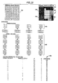
- FIG. 25 provides further explanation of the processing of grayscale images.
- a grayscale image 400 formed of pixels 401; and having four possible levels of gray can be represented in binary form as shown at 402.
- each pixel in binary representation 402 has its intensity level represented by a value of 0-3.
- Shrunken range blocks 366 can be constructed from the binary representation 402. First, four binary representation of range blocks 364 can be constructed as the lower left (1), lower right (2), upper left (3), and upper right (4) quadrants of binary image representation 402. These range block binary representations are then processed by shrinking techniques as described above to form shrunken range blocks 404.
- Binary representation 402 is also divided into binary domain bliks 406.
- the binary domain blocks are numbered 1-16 in order from left to right and from bottom to top of binary representation 402.
- Each of binary domain bloks 406 are a 2x2 pixel array of non-overlapping subsets of binary image representation 402.
- the domain block size is chosen to be the same as the shrunken range block size.
- the corresponding fractal transform 410 for grayscale input image 60 is thus a list of identifiers consisting of the "addresses" of the shrunken range blocks and associated vertical scaling parameters, one address and set of vertical scaling parameters being associated with each domain block, as shown in Fig. 26.
- Fig. 27 shows in detail a preferred method for automatically creating a fractal transform representative of grayscale image data in accordance with the present invention.
- digital image data representing a grayscale image is stored in buffer A of a data processor.
- a range block pointer for buffer A and a shrunken range block pointer for buffer B are initialized.
- predetermined procedures are applied to the range block of buffer A specified by the range block pointer. Such procedures include local affine transforms, such as rotation, reflection, or inversion prior to shrinking to obtain a greater number of shrunken range blocks for a given input image.
- the processed range blocks are then stored into buffer B at the locations indicated by the shrunken range block pointers.
- the range block pointer for buffer A and shrunken range block pointer for buffer B are then appropriately incremented at step 506, and the range is examined at step 508 to see whether all range blocks have been accessed. If not, steps 504 and 506 are repeatedly executed until all range blocks have been accessed.
- a domain block pointer for buffer A is initialized at step 512 and the shrunken range block pointer for buffer B is initialized in step 514.
- vertical scaling parameters P and Q are determined to minimize the L2 distance between the domain block addressed by the domain block pointer and the shrunken range block addressed by the range block pointer.
- L distances are used to measure the distances between graphs of functions rather than between sets of points.
- a digitized grayscale image can be thought of as a function formed from a two dimensional array of indices representing pixel locations in an image indicating the intensity value associated with the pixels. That is, the function f(i,j) represents the intensity at pixel i,j where i,j specify the location of the pixel in the image array.
- L distance compares two functions by appropriately summing and in some way averaging the differences between the intensities at each pixels It is an L2 distance if the differences are squared before they are summed, in which case the "averaging" is achieved by taking the square root of the sum. It is an L1 distance if the absolute values of the differences are utilized. If the L distance between two images is small then the two images look alike. L distances have the advantage that they generally can be calculated faster and easier than Hausdorff distances. In particular, a weighted L2 distance D L is used in the preferred embodiment to select vertical scaling parameters P and Q and is expressed as;
- the distance between digital grayscale images A and B can be measured using both Hausdorff distances and using L distances.
- the images are treated as a sets of points in a three dimensional array and in the second case they are treated as functions.
- L2 distances are used in selecting P and Q values.
- the Hausdorff distance between the domain block specified by the domain block pointer and the shrunken range block specified by the shrunken range block pointer and scaled by P and Q is determined.
- the Hausdorff distance is computed in the same manner as described with respect to Fig. 10.
- a determination is then made at step 520 if the value computed at step 518 is less than the currently stored value. If so, the currently stored value is replaced by the value just computed at step 518, along with the identifier of the shrunken range block which was used to generate the value just computed. If the value computed at step 518 is not less than the currently stored value, the value just computed is discarded.
- the range block pointer is incremented and a determination made as to whether all range blocks have been checked. If not, the method of Fig. 22 loops back to steps 516-522 until all shrunken range blocks have been checked.
- the identifier stored by the loop consisting of steps 516-522 is then appended at step 526 to a list of identifiers each representing one of the domain blocks of the input image data stored in buffer A.
- the domain block pointer is incremented at step 528 and a determination made whether all domain blocks have been processed. If not, steps 516-528 are repeatedly executed until all domain blocks have been processed.
- the list of identifiers, each corresponding to one of the domain blocks of the original input data, is then output at step 532 as the fractal transform according to this method of image data representing the input grayscale image.
- Fig. 28 illustrates how a grayscale image is recovered from a fractal transform 410 (which includes scaling parameters).
- An arbitrary initial image 534 and a fractal transform 478 are input to a decompression system 536, preferably embodied in a data processor.
- Initial image 534 is loaded into a buffer A.
- a buffer B is partitioned into domain blocks; and into each domain block is read a shrunken range block which is specified by the corresponding address of fractal transform 410, scaled as specified by the vertical scaling parameters.
- the shrunken range block is constructed from initial image 534 in buffer A.
- Image 534 in buffer A is treated, addressed, and processed into shrunken range blocks, in exactly the same manner as the original image.
- Each of the identifiers forming the grayscale fractal transform corresponds to one of the domain blocks in buffer B of Fig. 28 and is used to select a shrunken range block from buffer A to read into the corresponding domain block, thus forming an interim image in buffer B.
- the interim image in buffer B is now read back into buffer A, and buffer B is cleared.
- the steps of reading into each domain block of buffer B a shrunken range block of buffer A specified by a corresponding address of the fractal transform to form an interim image, and reading the interim image of buffer B into buffer A are repeated either a prescribed number of times or until "convergence" is achieved.
- the number of iterations of the steps of placing shrunken range blocks in buffer B and replacing contents of buffer A with contents of buffer B depends on the dimensions (measured in pixels) of the domain blocks and range blocks.
- the number of iterations may also be determined experimentally, by detecting convergence, defined as when the successive images in buffer B do not change by more than a predetermined amount.
- the decoded image is the one which is finally obtained after the iterative process is complete.
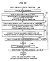
- Fig. 29 shows a logic flow diagram which constitutes a preferred embodiment for decoding a grayscale fractal transform such as the one generated by the method of Fig. 27.
- an initial image is supplied to buffer B, as indicated at step 550.
- a main loop counter, a domain block pointer for buffer B, and a fractal transform pointer are initialized, as indicated in step 552.
- the next entry of the fractal transform as specified by the fractal transform pointer, is obtained at step 554 and a corresponding shrunken range block is created from buffer A.
- the range block is then scaled with vertical scaling parameters P and Q and read into a domain block of a corresponding position in buffer B.
- step 556 domain block pointer for buffer B and the fractal transform pointer are incremented.
- the main loop counter is incremented at step 560. If the prescribed number of iterations has not been reached (Step 562), the method loops back to (step 562) and creates a domain block in buffer B from each fractal transform entry. The process continues until the prescribed number of iterations has been reached. At that time, the contents of buffer B are provided as data representative of the grayscale image previously compressed into the input fractal transform.
- the present invention also provides a method for enhancing images.
- Image data representing a grayscale image at a first resolution is stored in the data processor. For example, data from an image comprising an array of 256 x 256 pixels is supplied as input to the method of Fig. 27.
- a fractal transform is obtained using the method.
- the fractal transform is then decoded at a second resolution higher than the first resolution to produce output image data by decoding the fractal transform using the method of Fig. 29 including a pair of larger buffers to produce an output image array larger than 256 x 256.
- use of buffers in the method of Fig. 29 to provide a 512 x 512 output array yields an image having a resolution of twice that of the original input image.
- this technique can be used to provide a scalable font. That is, fractal transforms representing the symbols of the type face can be decoded to any desired resolution to provide multiple fonts of the type face symbols at any desired size.
- the invention may also be used to compress and decompress color images, as shown in Fig. 30.
- Digital data representing a color image is input and a trio of grayscale fractal transforms are produced, one for each of primary colors red, green, and blue.
- the three fractal transforms are concatenated to form a color fractal transform.
- the color fractal transform is separated into individual fractal transforms representing grayscale fractal transforms of red, green, and blue images.
- the individual fractal transforms are then decoded using, for example, the method shown in Fig. 29, to produce red, green, and blue intensity images. These intensity images are combined in a manner well known in the art and are output as a decompressed color image.
- the apparatus of Fig. 31 includes a host interface 600, memory 602, 604, 605, and 606, a memory interface circuit 610, a digital signal processor 612, and display output interface 613 on a printed circuit board which is compatible with PC/AT type computers based on the Intel 80286 central processing unit.
- the digital signal processor 612 and the memory interface 610 are connected to a PC expansion bus 611; and for receiving commands and data.
- the preferred digital signal processor 612 is a TMS320C30 manufactured by Texas Instruments, Incorporated. Details concerning the operation of the preferred digital signal processor 612 are available in the literature supplied by the manufacturer.
- the digital signal processor 612 employed in the disclosed embodiment is capable of performing a wide variety of floating point operations, the purpose for which it is used in the present invention is to provide high speed implementation of the arithmetic portions of a fractal transform decoding method, such as shown in Fig. 29. Accordingly, it will be understood that the other functions which could be carried out by the digital signal processor 612 are not employed in the disclosed embodiment.
- the digital signal processor 612 generally operates on thirty two bit data, in the disclosed embodiment, it adds and multiplies signed eight bit data provided by the memory interface 610 in response to a sequence of instructions contained in the program code ROM 602.
- These primary components operate to decode a set of range block addresses and transfer the results of the decoding process to the screen buffer 604 and 605, forming display memory banks A and B, which in the disclosed embodiment consists of a single 262,144 by 4 bit multiport video RAM TMS44C251 manufactured by Texas Instruments, Incorporated. Details concerning the operation of the preferred display memory banks A and B are available in the literature supplied by the manufacturer.
- the data set representing an image is an array of 256 pixels by 256 pixels, although it will be appreciated that the size of this array is arbitrary and that a larger array gives rise to greater resolution. Moreover, it should be understood that the data set representing the image is the same for the display resolution, the screen buffer resolution, and for all arithmetic calculations.
- each pixel intensity value is represented by an eight bit value so that images having two hundred fifty six gray or pseudo-color intensity levels can be decoded, although it will be appreciated that the size of this array is arbitrary and that more than.eight bits per pixel gives rise to more than two hundred fifty six intensity levels, while less than eight bits per pixels gives rise to less than 256 intensity levels. In particular, twenty four bits per pixel would give rise to sufficient intensity levels to describe two hundred fifty six intensity levels each of red, green and blue primary components.
- the preferred display memory banks A and B although physically one device, are conceptually treated as two banks of memory.
- One bank is thought of a containing the "current image” and is used as the source of image data.
- the other is thought of as containing the "new image” and is used as the destination of image data.
- the banks are distinguished by a memory start address offset which in the case of bank A is 0 and in the case of bank B is 131,076 (measured in four bit memory locations).
- Each bank is of sufficient size to contain an entire 256 x 256 x 8 bit image.
- the memory interface 610 contains address generators to generate arrays of data corresponding to square subimages.
- the subimages are determined by a row and column address of the upper left hand corner of the subimage and a size.
- the subimage with upper left hand corner row equal to R and column equal to C and dimension S is denoted by sub(R,C,S).
- Sub(R,C,S) contains S times S pixel locations and contains all the pixel locations from row R to row R+S-1 and from column C+S-1.
- the host interface 600 receives and transmits signals and data from an expansion bus 611 of an IBM PC/AT on PC address, data and bus control lines 615. Data and addresses are sent to the memory interface 610 on the lines 617.
- the memory interface 610 consists of memory address generators and address sequencers. Two types of data transmit the memory interface 610. Image codes are placed into and retrieved from program data RAM 606 which is 4096 by 8 bits. The image code is preceded by a byte of data, the format byte. The low four bits, bits 0,1,2,3, of the format byte determine the domain block size and therefore the range block size, since the range block size is always twice the domain block size in the disclosed embodiment. Valid values of the domain block size are 4-16. Both the domain blocks and range blocks are square in the disclosed embodiment. Thus, one dimension completely specifies the domain block size.
- the format byte is stored in a static RAM format register in the memory interface 610.
- the format byte is used by the digital signal processor 612 to compute the actual dimensions of the displayed image in pixels.
- the dimension of the displayed image may be somewhat less than 256 by 256. It is determined as the largest number of pixels which is a multiple of the domain block size and which is simultaneously no larger than 256. For example, if the domain block size is 5, then the image width and height in pixels is 255 and not 256. This is because 51 times 5 is 255, which number is not larger than 256, while 52 times 5 is 260, which exceeds 256. The number is computed by integer dividing 256 by 5 and then integer multiplying by 5.
- a list of image size values as a function of format value is now provided in the format i,f; where i is image size and f is format value: 256,4; 255,5; 252,6; 252,7; 256,8; 252,9; 250,10; 253,11; 252,12; 247,13; 252,14; 255,15; 256,16.
- the result is stored in an eight bit image size static RAM register in the memory interface 610.
- An address sequencer in the memory interface 610 uses FORMAT (the format register value), generates addresses in the program data RAM 606 to store the image codes which are transmitted from the host interface 600 into the memory interface 610.
- the program data RAM 606 consists of 4096 memory locations, each one byte wide.
- An image code may consist of up to 2048 codes, each of which occupies two bytes of the program data RAM.
- CODELENGTH the number of two-byte program data RAM words which contain valid data, is the square of (the value in image size divided by the value in FORMAT).
- CODELENGTH varies between 256 and 2048 as the value in format varies between 4 and 16.
- the sixteen bits of the first CODELENGTH words in the program data RAM contain both address and transform information. The partitioning of each such word between address and transform information depends on the value in the format register according to the following formula:
- the address bits are divided in equal parts to form a row address and a column address according to the following table:
- pixel row and column addresses are computed by multiplying the row address and column address values by the domain block size stored as the value in FORMAT.
- the address generator of memory 610 then determines physical memory address in the display memory banks 604 and 605.
- the transform bits are used, together with the values in NUMSCALE and DENOMSCALE registers in the memory interface 610, to carry out the grayscale fractal transform decoding operation.
- the digital signal processor 612 receives both of the signed eight bit NUMSCALE and DENOMSCALE values over the lines 619. In the disclosed embodiment, these values are selected by an operator and are fixed for an entire image computation. It will be understood that providing a larger program data RAM would permit distinct NUMSCALE and DENOMSCALE values to be used for each code word.
- the NUMSCALE and DENOMSCALE values are loaded from the PC/AT host to the host interface on lines 615 and from the host interface to the NUMSCALE and DENOMSCALE registers in the memory interface 610 on lines 617.
- the decoding steps of the grayscale fractal transform are carried out in an initialization step and repeated decoding iteration steps.
- the instructions required to carry out the decoding procedure are loaded from the program ROM 602 which is connected to the digital signal processor 612.
- Initialization Step An initialization signal is sent from the PC/AT host on the lines 615 to initialize the memory interface 610.
- the memory interface 610 now receives twenty six bits, the first eight of which are stored in the format register, the next nine of which are stored in the NUMSCALE register and the final nine of which are stored in the DENOMSCALE register.
- a code counter is now initialized to the value of 16 times CODELENGTH. Bits are now loaded from the PC/AT host over the data lines 615 to the host interface and from there over the data lines 617 to the memory interface 610.
- An address sequencer in the memory interface 610 having been initialized by the initialization signal above, provides successive addresses in the program data RAM 606 and transfers the data bits it receives to the byte memory areas so addressed.
- the code counter is decremented with each bit and the data transfer process halts when it reaches zero.
- a signal is then sent to the digital signal processor 612 to load the program from the program code ROM 602.
- the values in the NUMSCALE and DENOMSCALE registers are transferred to memory locations in the RAM of the digital signal processor 612.
- the value of FORMAT is also transferred to a memory location in the RAM of the digital signal processor 612, which computes and stores the value of CODELENGTH as described above.
- Another digital signal processor RAM address location, display bank, is cleared.
- Decoding Iteration Step A memory location configured as a block counter in the RAM of the digital signal processor 612 is set at the starting address of the program data RAM 606, which is contained in the program code ROM 602.
- Each Decoding Iteration Step consists of CODELENGTH iterations of Block Decoding Steps.
- the value of display bank is sent to the memory interface 610 and stored in a bank register on the memory interface 610.
- Block Decoding Step At the start of a Block Decoding Step, the value of BLOCK COUNTER in the digital signal processor 612 is passed on the data lines 619 to the memory interface 610. The eight bits of data at that address in the program data RAM and the next eight bits of data are passed back to the memory interface 610 on data lines 619.
- the transform bits of the code word are sent on data lines 13 to the digital signal processor 612 and stored in a memory location, Q, in the digital signal processor 612.
- the row and column address bits of the code word are used by the display address generator on the memory interface 610 to generate the addresses of a square block, with horizontal and vertical dimension equal to two times FORMAT of pixel data in the display memory bank.
- the addresses are generated in display memory bank B 605.
- the upper left hand corner of the square block is generated as that pixel on the FORMAT times row address row and format times column address column.
- the image data in this square block is SUB(ROW ADDRESS x FORMAT,COLUMN ADDRESS x FORMAT,2 x FORMAT).
- the address generator initializes counters with values i and j at 0 and then increments j until j reaches FORMAT, at which time it is reset to 0. When j is reset, then i is incremented until i reaches FORMAT when it is reset to Q.
- a register in the digital signal processor 612, PIXEL is cleared. For each value of i and j between 0 and FORMAT-1 inclusive, the byte values at the byte of pixel data stored at the address locations of the four pixels in SUB(SUBROW, SUBCOL, 2) is sent over the address lines of 619 to the memory interface 610 and then over the data lines of 619 to the digital signal processor 612 and accumulated in the PIXEL register.
- a second address generator in the memory interface 610 determines destination addresses in the display memory.
- the pixel coordinates of the upper left hand coordinates are computed by the second address generator.
- the addresses of the FORMAT times FORMAT pixels in SUB(DESTROW,DESTCOL,FORMAT) are computed as the counters i and j vary.
- counters i and j are cleared and BLOCKCOUNT is incremented.
- Block Decoding Step is repeated CODELENGTH many times with the incremented blockcount values.
- the value of display bank is replaced by 1 - the value of display bank and consequently alternates between 0 and 1.
- the Decoding Iteration Step is then completed.
- the display of the image is carried out essentially asynchronously with the computational decoding. Pixel values are indeed read out of the display memory asynchronously, but the memory bank which is used as the source of the display pixels is specified by the value of display bank.
- the display output interface 613 provides the R-G-B output.
- the video output logic timing device 617 drives the preferred color pallet, a Brooktree Bt453RAMDAC, not shown in Fig. 31.
- the ratio of the image code to the decoded image size is called the compression ratio of the device.
- the compression ratio of the device may be computed by dividing twice CODELENGTH by the square of image size.
- the disclosed embodiment yields compression ratios varying from 1:16 when FORMAT contains the domain block size value of 4 to a compression ratio of 1:128 when the value of FORMAT is 16.
- the restriction of FORMAT values to vary between 4 and 16 is arbitrary. Larger values of FORMAT lead to larger compression ratios.
- An intended purpose of the disclosed decoding device is to provide an economical means of decoding images which have been encoded by the grayscale fractal transform.
- the usefulness of the device can also be measured in the compression ratio which it achieves.
- the compression ratio can be effectively increased by compressing the fractal transform codes by traditional compression of a grayscale fractal transform
- publicly available Huffman encoding schemes could be used to encode the fractal transform codes.
- the Huffman encoded fractal transform codes are then Huffman decoded before transmission to the disclosed apparatus for decoding the fractal transform.
- fractal transform techniques described herein has a significant advantage over prior art techniques such as vector quantization and Huffman coding in that no look-up tables are used.
- the compression ratio can be easily changed, the system can be used in an adaptive mode, useful in applications such as DVI and preparation of old movies for transmission along telephone lines.
- Fig. 32 is a logic flow chart of a method for generating compressed digital data representing image information in a motion picture, by a data processor, for storage or transmission.
- first and second processing buffers are initialized with predetermined image data.
- the processing buffers are initialized to values of 0.
- the processing buffers are formed to store grayscale pixel values of a square image array.
- the processing buffers provide storage of a 256 x 256 array of 8-bit pixels.
- the value of a counter in the data processor is also initialized at step 702.
- image information contained in the first frame of the motion picture to be processed is digitized to produce digitized image data.
- the image information may be digitized at the same resolution as the processing buffers.
- the image information from the first frame of the movie is digitized into a 256 x 256 array of pixels having an 8-bit grayscale value.
- the digitized image data from the first frame of the movie is stored in a frame buffer.
- the counter value is then checked to determine if the value is greater than a predetermined limit value.
- the counter is used for the purpose of repeating the processing of the first frame for a fixed number of times, for example, 8. That is, the limit value referred to in step 708 is set to 8. If the counter value is greater than the limit value, image information from the next sequential frame of the movie is digitized to produce digitized next frame image data and the digitized next frame image data is stored in a frame buffer. If the counter value is not greater than the limit value, as determined in step 708, step 710 is bypassed, with the result that image data from the first frame remains in the frame buffer.
- image data from the frame buffer is stored into the first processing buffer. This image data is then processed in the same manner as set forth in Fig. 5. Specifically, domain blocks are created in step 714. Next, at step 716, shrunken range blocks are created in the second processing buffer. For each domain block, the closest shrunken range block is selected at step 718 and the selected shrunken range block is used to replace the corresponding domain block in the first processing buffer at step 720.
- the set of identifiers of the selected shrunken range blocks is then used at step 722 to form a fractal transform such as fractal transform 410, shown in Fig. 26.
- This fractal transform is referred to as a current transform.
- the current transform which comprises compressed digital data representative of the image information in the first frame of the movie, is then provided as output at step 724, and the contents of the first processing buffer are copied into the second processing buffer at step 726.
- step 728 the counter value is incremented and a determination is made at block 730 if all frames of the movie have been processed. If not, processing returns to step 708. If all frames have been processed, the method ends at 732.
- a logic flow chart of a method for automatically generating digital data representing the frames of a motion picture The data is generated by a data processor from a sequence of current transforms, each having a set of identifiers.
- the data processor includes a memory having a plurality of buffers, each having a plurality of addressable areas specified by a buffer address.
- Each of the identifiers corresponds to an addressable area in the buffers and includes a buffer address and a procedures specification.
- a pair of buffers A and B are provided, corresponding in size to the processing buffers discussed with respect to Fig. 32.
- buffers A and B in the preferred embodiment each have a size sufficient to store an array of 256 x 256 by 8 bits.
- an initialization step is performed in which a predetermined pattern of digital data is stored into at least one of the buffers, buffer B, designated as a source buffer.
- buffers A and B are initialized to all 0's.
- a current transform preferably generated by a process such as shown in Fig. 32, is input at step 802 from the sequence of current transforms which constitute compressed digital data representing a motion picture.
- the digital data in buffer A is formed into domain blocks, each corresponding to an identifier in the input current transform.
- the digital data in buffer B is formed into shrunken range blocks, in the same manner as is discussed above with respect to Fig. 13.
- each domain block in buffer A is replaced by a shrunken range block.
- a pattern of data is determined which corresponds to each of the identifiers. This pattern of data is determined by applying the procedures specified in that identifier to the portion of the source buffer, buffer B, indicated by the buffer address in the identifier.
- the patterns of data are stored into the addressable areas of buffer A, designated as a destination buffer, as indicated by the addresses of the corresponding identifiers.
- each domain block of buffer A is replaced by a shrunken range block of buffer B. This process is identical to that described above with respect to. Fig. 13.
- step 810 the contents of the destination buffer are provided as data representative of an image in the frame. That is, image data from buffer A is output as digital data representative of an image in the frame. This image corresponds to the frame represented by the current transform input in step 802.
- step 812 a determination is made as to whether all current transforms have been processed; that is, have images corresponding to all desired frames been processed. If so, the process ends at step 814. Otherwise, the contents of the destination buffer are copied into the source buffer. That is, as shown at step 816, the contents of buffer A are copied into buffer B and processing returns to step 802 to decompress the next current transform of the sequence.
- the sequence of sets of image data output at step 810 constitutes decompressed image data representing each frame of a motion picture.
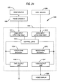
- Fig. 34 is a block diagram of apparatus 1000 for providing a videophone.
- Apparatus 1000 includes two latch-and-hold input units 1011 and 1012, a control logic unit 1013, two data processors 1014 and 1015 (respectively functioning as a videophone encoder and a videophone decoder), and two output units 1017.
- Apparatus 1000 has two functional modes: encoding and decoding.
- Control logic unit 1013 selects either the encoding mode or the decoding mode as determined by input data.
- a video source 1002 such as a video camera, provides an analog signal to a frame grabber circuit 1006 which converts each frame of video from source 1002 into digital data and stores the digital data in frame grabber circuit 1006.
- Control logic unit 1013 causes video input unit 1011 to read digital data stored in frame grabber circuit 1006 and pass the data to videophone encoder 1014.
- Videophone encoder 1014 is a fractal encoder of the type described previously with respect to Fig. 6.
- Videophone encoder 1014 processes the digital video data which it receives from control logic unit 1013. This processing produces fractal transforms for the frames, which are then output through data output unit 1016.
- Data output unit 1016 may be a standard telephone modem circuit.
- fractal transforms are supplied by a data source 1004, which may also be a standard telephone modem circuit.
- Control logic unit 1013 causes data input unit 1012 to read and accumulate the data supplied by data source 1004 and pass it to videophone decoder 1015.
- Videophone decoder 1015 is a fractal decoder of the type described with respect to Fig. 14.
- Videophone decoder 1015 processes the fractal transforms which are received from control logic unit 1013. The processing results in digital video data which is sent from decoder 1015 to video output unit 1017. This output unit transforms the digital data into analog data for display on the video display unit 1020.
- the present invention provides data compression methods and apparatus which exhibit higher performance than prior art methods and apparatus. Moreover, the present invention avoids the necessity for hour of manual operation of a computer to achieve compressed data. Since look-up tables are not required, the present invention can provide adaptive capabilities, while minimizing the amount of memory required.
- the invention provides the ability to represent and store images in a digital computer with scale-independent resolution using a two-dimensional array of numerical attributes of a digitized picture as input and providing an output which is a smaller data set from the original.
- the present invention can provide both exact and non-exact image representation by choice of appropriate block sizes and screen resolution.
- the invention further provides the ability to subject image data to multiple passes of an encoding and decoding process such that the image data emerges.the same as if it had been encoded and decoded only once.
Claims (34)
- Verfahen zur automatischen Verarbeitung digitaler Bilddaten, die aus Bildinformation bestehen, mit Hilfe eines Datenprozessors, umfassend die Schritte:
Speicherung der Bilddaten im Datenprozessor;
Erzeugen einer Vielzahl individuell adressierbarer Domänenblökke (34) aus den gespeicherten Bilddaten, wobei jeder der Domänenblöcke einen anderen Teil der Bildinformation darstellt, so daß die gesamte Bildinformation in wenigstens einem der Domänenblöcke enthalten ist;
Erzeugen einer Vielzahl individuell adressierbarer, kartierter Bereichsblöcke (36, 38, 40) aus den gespeicherten Bilddaten entsprechend unterschiedlichen Untersätzen der gespeicherten Bilddaten, wobei jeder der Untersätze eine individuelle Adresse hat; und
Repräsentieren der Bildinformation als einen Satz von Identifizierern der ausgewählten, kartierten Bereichsblöcke,
dadurch gekennzeichnet, daß
der Erzeugungsschritt für jeden der kartierten Bereichsblöcke den Unterschritt der Ausführung einer Schrumpfprozedur an einem der Untersätze der gespeicherten Bilddaten, der dem kartierten Bereichsblock entspricht, enthält, und
weiterhin enthaltend die Schritte:
Zuordnen individueller Identifizierer zu jedem der kartierten Bereichsblöcke, wobei jeder der Identifizierer für den entsprechenden kartierten Bereichsblock eine Adresse des entsprechenden Untersatzes der gespeicherten Bilddaten spezifiziert; und
für jeden der Domänenblöcke das Auswählen desjenigen kartierten Bereichsblocks, der gemäß vorbestimmten Kriterien dem Domänenblock am besten entspricht. - Verfahren nach Anspruch 1, bei dem die digitalen Bilddaten aus mehreren Bildpunkten bestehen und der Schritt der Erzeugung der Domänenblöcke den Unterschritt der Erzeugung der Domänenblöcke mit ungleichen Bildpunktanzahlen umfaßt.
- Verfahren nach Anspruch 1, bei dem die digitalen Bilddaten aus mehreren Bildpunkten bestehen und der Schritt der Erzeugung der Domänenblöcke den Unterschritt der Erzeugung der Domänenblöcke mit gleichen Bildpunktanzahlen umfaßt.
- Verfahren nach einem der Ansprüche 1 bis 3, bei dem der Schritt der Erzeugung einer Vielzahl individuell adressierbarer kartierter Bereichsblöcke die folgenden Unterschritte umfaßt:
Erzeugen von mehreren Anfangsbereichsblöcken mit größeren Bildpunktanzahlen als die Domänenblöcke;
Schrumpfen der Anfangsbereichsblöcke zur Erzeugung geschrumpfter Bereichsblöcke, die die gleiche Anzahl Bildpunkte haben, wie die Domänenblöcke; und
Verwenden der geschrumpften Bereichsblöcke zur Bildung der kartierten Bereichsblöcke. - Verfahren nach Anspruch 4, bei dem der Schrumpfungsschritt den Unterschritt der Auswahl gewisser Bildpunkte eines jeden Anfangsbereichsblocks zur Bildung eines entsprechenden geschrumpften Bereichsblocks enthält.
- Verfahren nach Anspruch 5, bei dem der Unterschritt der Bildpunktauswahl den Unterschritt der Auswahl von Bildpunkten umfaßt, die in den Bereichsblöcken in gleichen Abständen verteilt sind.
- Verfahren nach Anspruch 4, bei dem der Schrumpfungsschritt den Unterschritt der Mittelwertbildung benachbarter Bildpunkte umfaßt.
- Verfahren nach einem der Ansprüche 1 bis 7, bei dem der Schritt der Erzeugung einer Vielzahl individuell adressierbarer kartierter Bereichsblöcke den folgenden Unterschritt umfaßt:
Anwenden einer affinen Transformatin auf denjenigen Untersatz des gespeicherten Bildes, der dem kartierten Bereichsblock entspricht; und
wobei der Schritt der Zuordnung individueller Identifizierer den Unterschritt der Zuordnung individueller Identifizierer umfaßt, die jeweils sowohl eine Adresse als auch eine Spezifikation der affinen Transformation enthalten. - Verfahren nach Anspruch 8, bei dem der Schritt der Erzeugung einer Vielzahl individuell adressierbarer Bereichsblöcke den Unterschritt der Invertierung des kartierten Bereichsblocks umfaßt.
- Verfahren nach einem der Ansprüche 1 bis 9, bei dem der Schritt der Erzeugung der Domänenblöcke den Unterschritt der Zuordnung jedes Teils der gespeicherten Bildinformation zu nur einem der Domänenblöcke derart umfaßt, daß die Domänenblöcke nicht überlappen.
- Verfahren nach einem der Ansprüche 1 bis 10, bei dem der Schritt der Auswahl des am besten entsprechenden der kartierten Bereichsblöcke für jeden Domänenblock den Schritt der Auswahl des kartierten Bereichsblocks umfaßt, der die minimale Hausdorff-Distanz vom Domänenblock umfaßt.
- Verfahren nach einem der Ansprüche 1 bis 10, bei dem der Schritt der Auswahl des am besten entsprechenden der kartierten Bereichsblöcke für jeden Domänenblock den Schritt der Auswahl des kartierten Bereichsblocks mit der minimal modifizierten Hausdorff-Distanz umfaßt, die als D [db, mrb] +D [1-db, mrb] umfaßt, wobei D eine Distanz ist, die zwischen einem Paar Datensätze berechnet ist, die jeweils ein Bild repräsentieren, db ein Domänenblock, mrb ein kartierter Bereichsblock, 1-db der Kehrwert eines Domänenblocks und 1-mrb der Kehrwert eines kartierten Bereichsblocks ist.
- Verfahren nach einem der Ansprüche 1 bis 10, bei dem der Schritt der Auswahl des am besten entsprechenden der kartierten Bereichsblöcke die folgenden Unterschritte umfaßt:
für jeden Domänenblock Berechnung der gewichteten L²-Distanz DL von jedem der kartieren Bereichsblöcke als
- Verfahren nach einem der Ansprüche 1 bis 13, bei dem der Schritt der Erzeugung kartierter Bereichsblöcke den Schritt der Erzeugung eines kartierten Bereichsblocks umfaßt, der einen Escape-Block hat, der die gleiche Größe wie die kartierten Bereichsblöcke aufweist und digitale Daten enthält, die ein vollständig weißes Bild repräsentieren.
- Verfahren nach einem der Ansprüche 1 bis 14, bei dem die digitalen Bilddaten eine Vielzahl Bildpunkte aufweisen, die jeweils einen aus einer Vielzahl von Grauskalawerten haben.
- Verfahren nach Anspruch 15, bei dem der Auswahlschritt die folgenden Unterschritte umfaßt:
Transformieren der Grauskalawerte der Bildpunkte eines jeden Domänenblocks durch eine lineare Funktion, die wenigstens einen Vertikalmaßstabsparameter enthält;
Transformieren der Grauskalawerte der Bildpunkte der geschrumpften Bereichsblöcke durch die lineare Funktion;
für jeden Domänenblock die Auswahl desjenigen der kartieren Bereichsblöcke mit transformierten Bildpunktwerten, der den transformierten Bildpunktwerten des Domänenblocks gemäß dem ersten vorbestimmten Kriterium am besten entspricht; und
wobei der Schritt der Repräsentierung der Bildinformation den Unterschritt der Repräsentierung der Bildinformation als einen Satz von Werten umfaßt, die jeweils einen Identifizierer des ausgewählten, kartierten Bereichsblocks und den wenigstens einen vertikalen Maßstabsparameter enthalten. - Verfahren nach Anspruch 16, bei dem das erste Kriterium die Minimierung der Hausdorff-Distanz zwischen jedem Domänenblock und dem ausgewählten geschrumpften Bereichsblock enthält.
- Verfahren nach Anspruch 16, bei dem die Unterschritte der Transformation von Bildpunktwerten der Domänenblöcke und der geschrumpften Bereichsblöcke die Auswahl des wenigstens einen vertikalen Maßstabsparameters zur Maximierung der Korrespondenz zwischen den Domänenblöcken und den geschrumpften Bereichsblökken gemäß einem zweiten vorbestimmten Kriterium umfaßt.
- Verfahren nach Anspruch 18, bei dem die ersten und zweiten vorbestimmten Kriterien verschieden sind.
- Verfahren nach Anspruch 19, bei dem das zweite vorbestimmte Kriterium die Minimierung der L²-Distanz zwischen den Domänenblöcken und den geschrumpften Bereichsblöcken umfaßt.
- Verfahren nach einem der Ansprüche 1 bis 20, bei dem die digitalen Daten ein Bewegungsbild repräsentieren, das eine Vielzahl einzelner aufeinanderfolgender Vollbilder aufweist, die jeweils Vollbildinformation enthalten, umfassend die folgenden, von einem Datenprozessor ausgeführten Schritte:
Initialisieren erster und zweiter Verarbeitungspuffer im Datenprozessor;
Speichern der digitalen Bilddaten im ersten Verarbeitungspuffer;
Erzeugen einer Vielzahl individuell adressierbarer Domänenblökke durch Erzeugen einer Vielzahl individuell adressierbarer Domänenblöcke im ersten Verarbeitungspuffer aus den gespeicherten Bilddaten des ersten Verarbeitungspuffers, wobei jeder der Domänenblöcke einen anderen Teil der Vollbildinformation repräsentiert, so daß die gesamte Vollbildinformation in wenigstens einem der Domänenblöcke enthalten ist;
Erzeugen einer Vielzahl individuell adressierbarer, kartierter Bereichsblöcke durch Erzeugen - im zweiten Verarbeitungspuffer aus den in dem zweiten Verarbeitungspuffer gespeicherten Daten - einer Vielzahl von individuell adressierbaren, gespeicherten Bereichsblöcken entsprechend unterschiedlichen Untersätzen der im zweiten Verarbeitungspuffer gespeicherten Daten, wobei jeder der Untersätze eine individuelle Adresse aufweist, wobei der Erzeugungsschritt für jeden der kartierten Bereichsblöcke den Unterschritt der Ausführung einer entsprechenden Prozedur an einem der Untersätze der Daten vom zweiten Verarbeitungspuffer umfaßt, die dem kartierten Bereichsblock entsprechen;
Zuordnen individueller Identifizierer durch Zuordnen individueller Identifizierer zu entsprechenden der kartierten Bereichsblöcke, wobei jeder der Identifizierer für den entsprechenden kartieren Bereichsblock eine Prozedur und eine Adresse des entsprechenden Untersatzes im zweiten Verarbeitungspuffer gespeicherter Daten spezifiziert;
Ausführen des Wählschrittes durch Wählen für jeden der Domänenblöcke des ersten Verarbeitungspuffers desjenigen der kartierten Bereichsblöcke des zweiten Verarbeitungspuffers, der entsprechend vorbestimmter Kriterien am besten entspricht;
Ausführen des zusätzlichen Schrittes des Ersetzens eines jeden der Domänenblöcke durch den entprechenden ausgewählten kartierten Bereichsblock;
Repräsentieren der Bildinformation durch Bildung einer laufenden Transformation als ein Satz der Identifizierer der ausgewählten kartierten Bereichsblöcke; und
Ausführen der zusätzlichen Schritte des Kopierens des Inhaltes des ersten Verarbeitungspuffers in den zweiten Verarbeitungspuffer;
Wiederholen der Speicherung, der Erzeugung erster und zweiter Verarbeitungspuffer, der Zuordnung, der Auswahl, des Ersatzes, der Bildung und des Kopierschrittes, bis alle Vollbilder digitalisiert worden sind; und
Zuführen der Sequenz laufender Transformationen für jedes der Vollbilder als komprimierte Repräsentation von Bildinformation im bewegten Bild. - Verfahren nach Anspruch 21, bei dem die Bilddaten aus dem ersten Rahmen eine vorbestimmte Anzahl wiederholt verarbeitet werden, um eine Serie von laufenden Transformationen zu erzeugen, die für das ersten Vollbild repräsentativ sind, und Bilddaten von jedem nachfolgenden Vollbild einmal verarbeitet werden, um eine einzelne laufende Transformation zu erzeugen, die für jedes nachfolgende Vollbild repräsentativ ist.
- Verfahren zum automatischen Erzeugung digitaler Daten, die die Vollbilder eines bewegten Bildes repräsentieren, durch einen Datenprozessor aus einer Folge laufender Transformationen, die durch das Verfahren nach Anspruch 21 erzeugt werden, wobei jede der Transformationen einen Identifizierer aufweist, der komprimierte digitale Daten enthält, die für die Vollbilder repräsentativ sind, wobei der Datenprozessor einen Speicher enthält, der mehrere Puffer aufweist, die jeweils mehrere adressierbare Bereiche aufweisen, die durch eine Pufferadresse spezifiziert werden, und jeder der Identifizierer einem adressierbaren Bereich in den Puffern entspricht und eine Pufferadresse und eine Prozedurspezifizierung enthält, wobei das Verfahren die folgenden, vom Datenprozessor ausgeführten Schritte umfaßt:
Initialisieren eines vorbestimmten Musters digitaler Daten in einem der Puffer, der als ein Quellenpuffer bezeichnet wird;
Eingeben einer laufenden Transformation und Speichern der laufenen Transformation in einem anderen der Puffer, der als Zielpuffer bezeichnet wird;
für jeden der Identifizierer Bestimmen eines Datenmusters entprechend jedem Identifizierer durch Anwenden der in jenem Identifizierer spezifizierten Prozedur auf den Teil des Quellenpuffers, der durch die Pufferadresse in jenem Identifizierer bezeichnet ist;
Speichern der Datenmuster in die adressierbaren Bereiche des Zielpuffers, die durch die entsprechenden Identifizierer spezifiziert werden;
Liefern des Inhalts des Zielpuffers als Daten, die für ein Bild in einem Vollbild repräsentativ sind;
Kopieren des Inhalts des Zielpuffers in den Quellenpuffer; und
Wiederholen der Eingabe-, Bestimmungs-, Speicher-, Lieferungs- und Kopierschritte für jede laufende Transformation der Folge. - Verfahren zum Erzeugen eines Bildes durch einen Datenprozessor aus einem Satz von Identifizierern, die durch das Verfahren von Anspruch 1 erzeugt werden, wobei der Datenprozessor einen Speicher enthält, der einen Puffer mit mehreren adressierbaren Bereichen hat, die durch eine Pufferadresse spezifiziert werden, und jeder der Identifizierer einem adressierbaren Bereich in dem Puffer entspricht und eine Pufferadresse enthält, enthaltend die folgenden, von einem Datenprozessor ausgeführten Schritte:
Speichern eines vorbestimmten Musters digitaler Daten im Puffer;
Bestimmen für jeden der Identifizierer eines Datenmusters entsprechend jedem Identifizierer durch Auswahl von Daten in einem Teil des Puffers, der durch die Pufferadresse in jeden Identifizierer bezeichnet wird;
Speichern der Datenmuster in adressierbare Bereiche entsprechend den Identifizierern;
Wiederholen der Bestimmungs- und Pufferspeicherschritte, bis vorbestimmte Kriterien erfüllt sind; und
Liefern des Inhalts des Puffers als Daten, die für ein Bild repräsentativ sind, wenn das vorbestimmte Kriterium erfüllt ist. - Verfahren nach Anspuch 24, bei dem die digitalen Bilddaten aus Bildinformation einer ersten Auflösung bestehen und die ausgegeben Bilddaten für das eingegebene Bild repräsentativ sind, mit einer zweiten Auflösung, die größer ist als die erste Auflösung.
- Verfahren nach Anspruch 24, bei dem der Datenprozessor einen Speicher enthält, der mehrere Puffer aufweist;
wobei der Schritt des Speicherns eines vorbestimmten Musters digitaler Daten das Speichern eines vorbestimmen Datenmusters in einem der Puffer enthält, der als ein Quellenpuffer bezeichnet wird;
wobei der Schritt des Bestimmens eines Datenmusters für jeden der Identifizierer die Bestimmung eines Datenmusters enthält, das jedem Identifizierer entspricht, durch den Teil des Quellenpuffers, der durch die Pufferadresse in jenen Identifizierer bezeichnet ist;
wobei der Schritt des Speicherns der Datenmuster das Speichern der Datenmuster in den adressierbaren Bereich eines weiteren der Puffer umfaßt, der als ein Zielpuffer bezeichnet wird, entsprechend dem Identifizierer;
wobei der Schritt der Wiederholung der Bestimmung und der Pufferspeicherschritte die Wiederholung der Bestimmung und der Zielpufferspeicherschritte umfaßt, wobei der Zielpuffer als der Quellenpuffer betrachtet wird, bis vorbestimmte Kriterien erfüllt sind, und
wobei der Schritt der Lieferung des Inhalts des Puffers die Lieferung des Inhalts der Zielpuffers als Daten umfaßt, die für ein Bild repräsentativ sind, wenn das vorbestimmte Kriterium erfüllt ist. - Verfahren nach Anspruch 26, bei dem die Identifizierer sowohl eine Pufferadresse als auch eine Prozedurspezifizierung enthalten, und
wobei der Schritt der Bestimmung eines Datenmusters für jeden der Identifizierer die Bestimmung eines Datenmusters entsprechend jedem Identifizierer durch die Anwendung der durch jenen Puffer spezifizierten Prozedur auf den Teil des Quellenpuffers umfaßt, der durch die Pufferadresse in jenem Identifizierer bezeichnet wird. - Verfahren nach Anspruch 26, bei dem der Schritt der Lieferung des Inhalts des Zielpuffers, wenn das vorbestimmte Kriterium erfüllt ist, den Unterschritt der Bestimmung umfaßt, wenn der Inhalt der Quellen- und Zielpuffer um weniger als eine vorbestimmte Größe differiert.
- Verfahren nach Anspruch 26, bei dem der Schritt der Lieferung des Inhalts des Zielpuffers als Daten, die für ein Bild repräsentativ sind, wenn das vorbestimmte Kriterium erfüllt ist, die Schritte der Bestimmung und der Speicherung in den Zielpuffer in vorbestimmter Wiederholungsanzahl umfaßt.
- Verfahren nach Anspruch 26, bei dem der Schritt der Speicherung von digitalen Daten in den Zielpuffer den Schritt der Speicherung wenigstens eines der Muster in jeden adressierbaren Bereich des Zielpuffers umfaßt.
- Vorrichtung zur automatischen Verarbeitung digitaler Bilddaten, die aus Bildinformation bestehen, enthaltend eine Einrichtung zum Speichern der Bilddaten; eine Einrichtung zum Erzeugen mehrerer individuell adressierbarer Domänenblöcke (34) aus den gespeicherten Bilddaten, wobei jeder der Domänenblöcke einen anderen Teil der Bildinformation repräsentiert, so daß die gesamte Bildinformation in wenigstens einem der Domänenblöcke enthalten ist; eine Einrichtung zum Erzeugen mehrerer individuell adressierbarer, gespeicherter Bereichsblöcke (36, 38, 40) aus den gespeicherten Bilddaten entsprechend den unterschiedlichen Untersätzen der gespeicherten Bilddaten, wobei jeder der Untersätze eine individuelle Adresse hat, wobei die Erzeugungseinrichtung eine Einrichtung enthält, um für jeden der kartierten Bereichsblöcke eine Schrumpfprozedur an einem der Untersätze der gespeicherten Bilddaten auszuführen, der dem kartierten Bereichsblock entspricht;
gekennzeichnet durch
eine Einrichtung zum Zuordnen individueller Identifizierer zu jedem der kartieren Bereichblöcke, wobei jeder der Identifizierer für den entsprechenden kartierten Bereichsblock eine Adresse des entsprechenden Untersatzes der gespeicherten Bilddaten spezifiziert;
eine Einrichtung, um für jeden der Domänenblöcke denjenigen der kartierten Bereichsblöcke auszuwählen, der gemäß vorbestimmter Kriterien am besten entspricht; und
eine Einrichtung zum Repräsentieren der Bildinformation als einen Satz von Identifizierern der ausgewählten kartiertern Bereichsblöcke. - Vorrichtung nach Anspruch 31, bei der die Einrichtung zum Zuordnen individueller Identifizierer eine Einrichtung zum Zuordnen individueller Identifizierer zu entsprechenden der kartierten Bereichsblöcke umfaßt, wobei jeder der Identifizierer für den entsprechenden kartierten Bereichsblock eine Prozdur und eine Adresse des entsprechenden Untersatzes gespeicherter Bilddaten spezifiziert.
- Vorrichtung nach Anspruch 31 oder 32 zur Erzeugung komprimierter digitaler Daten, die Vollbilder von Videobildinformation rerpäsentieren, die über eine Standardtelefonleitung zu übertragen ist,
wobei die Speichereinrichtung eine Vollbildergreifungseinrichtung enthält, um Videodaten entgegenzunehmen und Vollbilddaten zu speichern, die Bilddaten enthalten, die für Bildinformation in einem einzelnen Vollbild von Videodaten repräsentativ sind;
und enthaltend eine Steuereinrichtung, die mit der Vollbildergreifungseinrichtung und der Telefonleitung verbunden ist, um den Satz der Identifizierer der ausgewählten kartierten Bereichsblöcke der Telefonleitung als komprimierte Videodaten zuzuführen, die die Vollbilddaten rerpräsentieren. - Vorrichtung zum Erzeugen von Videodaten für die Anzeige auf einer Videoausgabeeinrichtung aus einer Folge laufender Transformationen, die von der Vorrichtung nach Anspruch 30 erzeugt werden und über eine Standardtelefonleitung empfangen werden und jeweils einen Satz Identifizierer aufweisen, die komprimierte digitale Daten enthalten, die für die Vollbilder repräsentativ sind, enthaltend:
eine Dateneingabeschaltung zum Empfangen und Ansammeln der komprimierten digitalen Daten;
einen Videodecoder, der mit der Dateneingabeschaltung verbunden ist und der umfaßt:
einen Speicher mit mehreren Puffern, die jeweils mehrere adressierbare Bereiche haben, die durch eine Pufferadresse spezifiert sind, und jeder der Identifizierer einem adressierbaren Bereich in den Puffern entspricht und eine Pufferadresse und eine Prozedurspezifizierung enthält, und
eine Einrichtung für:
das Speichern eines vorbestimmen Musters digitaler Daten in einem der Puffer, der als ein Quellenpuffer bezeichnet wird,
das Bestimmen für jeden der Identifizierer eines Datenmusters, das jedem Identifizierer entspricht, durch Anwenden der in jenem Identifizierer spezifizierten Prozedur auf den Teil des Quellenpuffers, der durch die Pufferadresse in jenem Identifizierer bezeichnet wird,
das Speichern der Datenmuster in den adressierbaren Bereich eines weiteren der Puffer, der als ein Zielpuffer bezeichnet wird, angegeben im entsprechenden Identifizierer, und
das Ausgeben des Inhalts des Zielpuffers als dekomprimierte digitale Daten, die für ein Vollbild von Bildinformation repräsentativ sind;
eine Videoausgabeschaltung, die mit dem Videodecoder verbunden ist, um die digitale Daten in Signale zur Anzeige eines Bildes auf einer Videoanzeigeeinrichtung umzuwandeln, und
eine Steuereinrichtung, die mit der Dateneingabeschaltung und dem Videodecoder verbunden ist, um die angesammelten digitalen Daten dem Videodecoder zuzuführen und um den Videodecoder anzuweisen, die dekomprimierten digitalen Daten zu erzeugen und der Videoausgabeschaltung zuzuführen.
Applications Claiming Priority (3)
| Application Number | Priority Date | Filing Date | Title |
|---|---|---|---|
| US07/375,840 US5065447A (en) | 1989-07-05 | 1989-07-05 | Method and apparatus for processing digital data |
| US375840 | 1989-07-05 | ||
| PCT/US1990/002674 WO1991000666A2 (en) | 1989-07-05 | 1990-05-17 | Method and apparatus for processing digital data |
Publications (2)
| Publication Number | Publication Date |
|---|---|
| EP0480941A1 EP0480941A1 (de) | 1992-04-22 |
| EP0480941B1 true EP0480941B1 (de) | 1995-06-28 |
Family
ID=23482588
Family Applications (1)
| Application Number | Title | Priority Date | Filing Date |
|---|---|---|---|
| EP90908910A Expired - Lifetime EP0480941B1 (de) | 1989-07-05 | 1990-05-17 | Verfahren und vorrichtung zur behandlung von numerischen daten |
Country Status (12)
| Country | Link |
|---|---|
| US (2) | US5065447A (de) |
| EP (1) | EP0480941B1 (de) |
| JP (1) | JP2968582B2 (de) |
| AT (1) | ATE124585T1 (de) |
| AU (1) | AU632333B2 (de) |
| BR (1) | BR9007504A (de) |
| CA (1) | CA2062965C (de) |
| DE (1) | DE69020564T2 (de) |
| DK (1) | DK0480941T3 (de) |
| ES (1) | ES2076368T3 (de) |
| NO (1) | NO301860B1 (de) |
| WO (1) | WO1991000666A2 (de) |
Families Citing this family (191)
| Publication number | Priority date | Publication date | Assignee | Title |
|---|---|---|---|---|
| US5218530A (en) * | 1989-09-11 | 1993-06-08 | Jastrzebski George B | Method of displaying and analyzing nonlinear, dynamic brain signals |
| DE69230440T2 (de) * | 1991-04-25 | 2000-04-13 | Unisys Corp | Verfahren und gerät zur adaptiven schwellwertverarbeitung von grauskalabildern |
| US5262878A (en) * | 1991-06-14 | 1993-11-16 | General Instrument Corporation | Method and apparatus for compressing digital still picture signals |
| US5271071A (en) * | 1991-06-21 | 1993-12-14 | Inds-Ops, Inc. | Digital nonalgorithmic method of compressing data which represents addresses and values |
| US5384867A (en) * | 1991-10-23 | 1995-01-24 | Iterated Systems, Inc. | Fractal transform compression board |
| US5875108A (en) * | 1991-12-23 | 1999-02-23 | Hoffberg; Steven M. | Ergonomic man-machine interface incorporating adaptive pattern recognition based control system |
| US7242988B1 (en) * | 1991-12-23 | 2007-07-10 | Linda Irene Hoffberg | Adaptive pattern recognition based controller apparatus and method and human-factored interface therefore |
| US10361802B1 (en) | 1999-02-01 | 2019-07-23 | Blanding Hovenweep, Llc | Adaptive pattern recognition based control system and method |
| US5903454A (en) | 1991-12-23 | 1999-05-11 | Hoffberg; Linda Irene | Human-factored interface corporating adaptive pattern recognition based controller apparatus |
| US8352400B2 (en) | 1991-12-23 | 2013-01-08 | Hoffberg Steven M | Adaptive pattern recognition based controller apparatus and method and human-factored interface therefore |
| US6850252B1 (en) | 1999-10-05 | 2005-02-01 | Steven M. Hoffberg | Intelligent electronic appliance system and method |
| US6400996B1 (en) | 1999-02-01 | 2002-06-04 | Steven M. Hoffberg | Adaptive pattern recognition based control system and method |
| US6418424B1 (en) | 1991-12-23 | 2002-07-09 | Steven M. Hoffberg | Ergonomic man-machine interface incorporating adaptive pattern recognition based control system |
| US6081750A (en) * | 1991-12-23 | 2000-06-27 | Hoffberg; Steven Mark | Ergonomic man-machine interface incorporating adaptive pattern recognition based control system |
| US5901246A (en) * | 1995-06-06 | 1999-05-04 | Hoffberg; Steven M. | Ergonomic man-machine interface incorporating adaptive pattern recognition based control system |
| FR2685796A1 (fr) * | 1991-12-26 | 1993-07-02 | Blanie Paul | Procede de codage visant l'organisation d'informations. |
| US5396228A (en) * | 1992-01-16 | 1995-03-07 | Mobile Telecommunications Technologies | Methods and apparatus for compressing and decompressing paging data |
| GB9204360D0 (en) * | 1992-02-28 | 1992-04-08 | Monro Donald M | Fractal coding of data |
| EP0562672A3 (en) * | 1992-03-22 | 1994-07-13 | Igp Res & Dev Ltd | Process of picture representation by data compression |
| US5416856A (en) * | 1992-03-30 | 1995-05-16 | The United States Of America As Represented By The Secretary Of The Navy | Method of encoding a digital image using iterated image transformations to form an eventually contractive map |
| US5862262A (en) * | 1992-03-30 | 1999-01-19 | The United States Of America As Represented By The Secretary Of The Navy | Method of encoding a digital image using adaptive partitioning in an iterated transformation system |
| EP0567697A1 (de) * | 1992-04-29 | 1993-11-03 | Yiu Keung Chan | Methode für Bildkompression im Raumbereich |
| KR0150955B1 (ko) * | 1992-05-27 | 1998-10-15 | 강진구 | 비트고정을 위한 영상압축방법과 신장방법 및 그 장치 |
| US5420967A (en) * | 1992-11-10 | 1995-05-30 | International Business Machines Corporation | Method and apparatus for the efficient generation of high quality images in a computer system utilizing an interconnected image state table |
| IL104636A (en) * | 1993-02-07 | 1997-06-10 | Oli V R Corp Ltd | Apparatus and method for encoding and decoding digital signals |
| US5426594A (en) * | 1993-04-02 | 1995-06-20 | Motorola, Inc. | Electronic greeting card store and communication system |
| US5784554A (en) * | 1993-05-28 | 1998-07-21 | Apple Computer, Inc. | Dynamic sampling profiler |
| JPH0778251A (ja) * | 1993-07-22 | 1995-03-20 | Xerox Corp | ソースベリファイ方法 |
| US5610657A (en) * | 1993-09-14 | 1997-03-11 | Envistech Inc. | Video compression using an iterative error data coding method |
| US5513128A (en) * | 1993-09-14 | 1996-04-30 | Comsat Corporation | Multispectral data compression using inter-band prediction |
| US5848198A (en) * | 1993-10-08 | 1998-12-08 | Penn; Alan Irvin | Method of and apparatus for analyzing images and deriving binary image representations |
| JPH07170521A (ja) * | 1993-12-15 | 1995-07-04 | Canon Inc | 画像処理装置 |
| US5673120A (en) * | 1993-12-24 | 1997-09-30 | Nec Corporation | Image output device |
| EP0739570A1 (de) * | 1994-01-14 | 1996-10-30 | Houston Advanced Research Center | Kompression von bewegtbildern mit splinegrenzen-wavelets |
| EP0672982B1 (de) * | 1994-03-18 | 2002-07-31 | Hewlett-Packard Company, A Delaware Corporation | Druckersystem mit komprimiertem Schriftsatzverfahren, das Speicherplatzeinsparüng ermöglicht |
| FR2717976B1 (fr) * | 1994-03-25 | 1996-05-10 | Thomson Consumer Electronics | Procédé de transmission d'images à format flexible pour systèmes de transmission de données à bas débit. |
| US5502439A (en) * | 1994-05-16 | 1996-03-26 | The United States Of America As Represented By The United States Department Of Energy | Method for compression of binary data |
| WO1995033336A1 (en) * | 1994-05-26 | 1995-12-07 | Hughes Aircraft Company | High resolution digital screen recorder and method |
| AUPM661494A0 (en) * | 1994-07-01 | 1994-07-28 | Commonwealth Scientific And Industrial Research Organisation | Fractal representation of data |
| JP3167865B2 (ja) * | 1994-07-28 | 2001-05-21 | 株式会社半導体エネルギー研究所 | 情報処理装置 |
| US6707484B1 (en) | 1994-07-28 | 2004-03-16 | Semiconductor Energy Laboratory Co., Ltd. | Information processing system |
| WO1996006494A2 (en) * | 1994-08-12 | 1996-02-29 | Neosoft, A.G. | Nonlinear digital communications system |
| US6055335A (en) * | 1994-09-14 | 2000-04-25 | Kabushiki Kaisha Toshiba | Method and apparatus for image representation and/or reorientation |
| US5732158A (en) * | 1994-11-23 | 1998-03-24 | Tec-Masters, Inc. | Fractal dimension analyzer and forecaster |
| US5754702A (en) * | 1994-12-02 | 1998-05-19 | Allied Signal Inc. | Scale oriented interband prediction method for image data compression and reconstruction |
| US5848177A (en) * | 1994-12-29 | 1998-12-08 | Board Of Trustees Operating Michigan State University | Method and system for detection of biological materials using fractal dimensions |
| US5754704A (en) * | 1995-03-10 | 1998-05-19 | Interated Systems, Inc. | Method and apparatus for compressing and decompressing three-dimensional digital data using fractal transform |
| US5838832A (en) * | 1995-04-03 | 1998-11-17 | Iterated Systems, Inc. | Method and system for representing a data set with a data transforming function and data mask |
| US5862263A (en) * | 1995-04-13 | 1999-01-19 | Samsung Electronics Co., Ltd. | Fractal image compression device and method using perceptual distortion measurement |
| US5717788A (en) * | 1995-04-18 | 1998-02-10 | Iterated Systems, Inc. | Method and system for analyzing data |
| KR0154739B1 (ko) * | 1995-04-19 | 1998-11-16 | 김광호 | 프랙탈 영상 압축 장치 및 방법 |
| US5917962A (en) * | 1995-06-06 | 1999-06-29 | Apple Computer, Inc. | Method and apparatus for partitioning an image |
| US5838833A (en) * | 1995-06-30 | 1998-11-17 | Minolta Co., Ltd. | Fractal image compression method and device and fractal image restoration method and device |
| KR100363244B1 (ko) * | 1995-06-30 | 2003-02-05 | 삼성전자 주식회사 | 프랙탈복호방법 |
| US5740282A (en) * | 1995-06-30 | 1998-04-14 | Iterated Systems, Inc. | System and method for contractive mapping resynchronization of a data transmission |
| US5721543A (en) * | 1995-06-30 | 1998-02-24 | Iterated Systems, Inc. | System and method for modeling discrete data sequences |
| US5867603A (en) * | 1995-07-10 | 1999-02-02 | Iterated Systems, Inc. | Method for transmitting fractal transform data to support different compressor/decompressor designs |
| AU722172B2 (en) * | 1995-08-24 | 2000-07-27 | Canon Information Systems Research Australia Pty Ltd | Method and apparatus for processing digital data |
| US5745392A (en) * | 1995-10-05 | 1998-04-28 | Chevron U.S.A. Inc. | Method for reducing data storage and transmission requirements for seismic data |
| JP3855286B2 (ja) * | 1995-10-26 | 2006-12-06 | ソニー株式会社 | 画像符号化装置および画像符号化方法、画像復号化装置および画像復号化方法、並びに記録媒体 |
| US5822721A (en) * | 1995-12-22 | 1998-10-13 | Iterated Systems, Inc. | Method and apparatus for fractal-excited linear predictive coding of digital signals |
| DE69716037T2 (de) | 1996-01-22 | 2003-07-03 | Matsushita Electric Ind Co Ltd | Verfahren zur kodierung und dekodierung von digitalen bildern |
| US5857036A (en) * | 1996-03-04 | 1999-01-05 | Iterated Systems, Inc. | System and method for the fractal encoding of datastreams |
| JPH09252468A (ja) * | 1996-03-15 | 1997-09-22 | Minolta Co Ltd | 画像圧縮装置 |
| US5870502A (en) * | 1996-04-08 | 1999-02-09 | The Trustees Of Columbia University In The City Of New York | System and method for a multiresolution transform of digital image information |
| US7469237B2 (en) * | 1996-05-02 | 2008-12-23 | Cooper David L | Method and apparatus for fractal computation |
| US6104834A (en) | 1996-08-01 | 2000-08-15 | Ricoh Company Limited | Matching CCITT compressed document images |
| EP0827111A1 (de) | 1996-08-30 | 1998-03-04 | Canon Kabushiki Kaisha | Verfahren und Vorrichtung zum Bearbeiten von Daten |
| US6094453A (en) * | 1996-10-11 | 2000-07-25 | Digital Accelerator Corporation | Digital data compression with quad-tree coding of header file |
| US6147010A (en) * | 1996-11-14 | 2000-11-14 | Micron Technology, Inc. | Solvent prewet and method to dispense the solvent prewet |
| US6480541B1 (en) | 1996-11-27 | 2002-11-12 | Realnetworks, Inc. | Method and apparatus for providing scalable pre-compressed digital video with reduced quantization based artifacts |
| WO1998031138A1 (en) * | 1997-01-13 | 1998-07-16 | John Overton | Automated system for image archiving |
| US5838820A (en) * | 1997-04-30 | 1998-11-17 | Bergman; Anthony J. | Pattern recognition apparatus and method |
| EP0928112A1 (de) | 1997-05-30 | 1999-07-07 | Sony Corporation | Vorrichtung und verfahren zur abbildung und erzeugung von bildern |
| US6321231B1 (en) * | 1997-08-11 | 2001-11-20 | Marshall, O'toole, Gerstein, Murray & Borun | Data management and order delivery system |
| US6498866B2 (en) | 1997-08-29 | 2002-12-24 | Canon Kabushiki Kaisha | Methods and devices for processing data and notably for compressing and decompressing images |
| FR2767999B1 (fr) * | 1997-08-29 | 2000-02-18 | Canon Kk | Procedes et dispositifs de traitement de donnees et notamment de compression et de decompression d'images |
| JPH1186014A (ja) * | 1997-09-08 | 1999-03-30 | Fujitsu Ltd | 文書画像表示方法および表示装置 |
| US6198851B1 (en) | 1997-09-22 | 2001-03-06 | Sony Corporation | Apparatus and method for encoding/decoding |
| FR2768889B1 (fr) * | 1997-09-23 | 1999-12-17 | Canon Kk | Dispositif et procede de traitement d'un ensemble de donnees et notamment de compression et de decompression de donnees d'images |
| EP0910042A3 (de) * | 1997-10-17 | 2000-03-08 | Sony Corporation | Verfahren und Vorrichtung zum Kodieren und Dekodieren digitaler Videodaten |
| JP3859325B2 (ja) * | 1997-10-22 | 2006-12-20 | ソニー株式会社 | 画像の反復変換復号化装置及び方法、並びに記録媒体 |
| US6339659B1 (en) * | 1997-10-28 | 2002-01-15 | Sony Corporation | Fractal coding/decoding of picture data using memory capacity information |
| DE19757045A1 (de) * | 1997-12-20 | 1999-06-24 | Thomson Brandt Gmbh | Verfahren zur fraktalen Codierung von Bild- oder Audiosignalen |
| KR100261106B1 (ko) * | 1997-12-29 | 2000-07-01 | 윤종용 | 영상 이미지 탐색 방법 및 장치 |
| JP3264245B2 (ja) * | 1998-04-03 | 2002-03-11 | ソニー株式会社 | 画像情報処理装置 |
| US6285794B1 (en) | 1998-04-17 | 2001-09-04 | Adobe Systems Incorporated | Compression and editing of movies by multi-image morphing |
| JP3583924B2 (ja) * | 1998-05-11 | 2004-11-04 | 株式会社沖データ | 解像度変換方法及び変換装置 |
| US7103640B1 (en) | 1999-09-14 | 2006-09-05 | Econnectix, Llc | Network distributed tracking wire transfer protocol |
| US7233978B2 (en) * | 1998-07-08 | 2007-06-19 | Econnectix, Llc | Method and apparatus for managing location information in a network separate from the data to which the location information pertains |
| US6661904B1 (en) | 1998-07-15 | 2003-12-09 | Personalogo | Method and system for automated electronic conveyance of hidden data |
| US6201897B1 (en) | 1998-11-09 | 2001-03-13 | Earth Resource Mapping | Transformation and selective inverse transformation of large digital images |
| US6624761B2 (en) | 1998-12-11 | 2003-09-23 | Realtime Data, Llc | Content independent data compression method and system |
| US6120451A (en) * | 1998-12-31 | 2000-09-19 | General Electric Company | Ultrasound color flow display optimization by adjustment of threshold |
| US6126605A (en) * | 1998-12-31 | 2000-10-03 | General Electric Company | Ultrasound color flow display optimization by adjusting dynamic range |
| US7904187B2 (en) | 1999-02-01 | 2011-03-08 | Hoffberg Steven M | Internet appliance system and method |
| US6604158B1 (en) | 1999-03-11 | 2003-08-05 | Realtime Data, Llc | System and methods for accelerated data storage and retrieval |
| US6601104B1 (en) | 1999-03-11 | 2003-07-29 | Realtime Data Llc | System and methods for accelerated data storage and retrieval |
| IL146562A0 (en) | 1999-05-19 | 2002-07-25 | Ics Systems Inc | Unified analog/digital waveform software analysis tool with video and audio signal analysis methods |
| US6775415B1 (en) * | 1999-05-25 | 2004-08-10 | George Mason University | Fractal image compression using reinforcement learning |
| US6633682B1 (en) * | 1999-06-21 | 2003-10-14 | New York University | Progressive fractal rendering |
| WO2001001579A1 (fr) * | 1999-06-28 | 2001-01-04 | Micro-Technology Corporation | Procede de generation d'un code comprime et procede de decompression d'un code comprime |
| US9843447B1 (en) * | 1999-09-09 | 2017-12-12 | Secure Axcess Llc | Authenticating electronic content |
| US7215776B1 (en) * | 1999-11-09 | 2007-05-08 | University Of New Hampshire | Method and apparatus for the compression and decompression of audio files using a chaotic system |
| US7286670B2 (en) | 1999-11-09 | 2007-10-23 | Chaoticom, Inc. | Method and apparatus for chaotic opportunistic lossless compression of data |
| US7215772B2 (en) * | 1999-11-09 | 2007-05-08 | Chaoticom, Inc. | Method and apparatus for remote digital key generation |
| US7181608B2 (en) | 2000-02-03 | 2007-02-20 | Realtime Data Llc | Systems and methods for accelerated loading of operating systems and application programs |
| EP1158804A3 (de) * | 2000-05-24 | 2003-12-17 | Matsushita Electric Industrial Co., Ltd. | Wiedergabevorrichtung zur Erzeugung einer Bildeinzeige |
| US20080005275A1 (en) * | 2000-06-02 | 2008-01-03 | Econnectix, Llc | Method and apparatus for managing location information in a network separate from the data to which the location information pertains |
| US6738520B1 (en) * | 2000-06-19 | 2004-05-18 | Intel Corporation | Method of compressing an image |
| US7110547B2 (en) * | 2000-06-20 | 2006-09-19 | University Of New Hampshire | Method and apparatus for the compression and decompression of image files using a chaotic system |
| US7046728B1 (en) | 2000-06-30 | 2006-05-16 | Intel Corporation | Method of video coding the movement of a human face from a sequence of images |
| US8692695B2 (en) | 2000-10-03 | 2014-04-08 | Realtime Data, Llc | Methods for encoding and decoding data |
| US9143546B2 (en) | 2000-10-03 | 2015-09-22 | Realtime Data Llc | System and method for data feed acceleration and encryption |
| US7417568B2 (en) | 2000-10-03 | 2008-08-26 | Realtime Data Llc | System and method for data feed acceleration and encryption |
| FR2815748B1 (fr) * | 2000-10-20 | 2003-01-24 | Canon Kk | Procede et dispositif de traitement et de decodage d'un signal numerique code |
| US7046851B2 (en) * | 2000-11-08 | 2006-05-16 | California Institute Of Technology | Image and video indexing scheme for content analysis |
| US7386046B2 (en) | 2001-02-13 | 2008-06-10 | Realtime Data Llc | Bandwidth sensitive data compression and decompression |
| JP3932379B2 (ja) * | 2001-10-02 | 2007-06-20 | 株式会社日立製作所 | 画像処理装置と撮像素子 |
| JP3882585B2 (ja) * | 2001-11-07 | 2007-02-21 | 富士ゼロックス株式会社 | 画像処理装置およびプログラム |
| FR2834376B1 (fr) * | 2001-12-28 | 2004-04-02 | St Microelectronics Sa | Adressage de memoire de blocs de reference en codage fractal |
| US20040100641A1 (en) * | 2002-02-20 | 2004-05-27 | Glenn Paul | Wireless click-and-deliver camera system |
| JP3882651B2 (ja) | 2002-03-20 | 2007-02-21 | 富士ゼロックス株式会社 | 画像処理装置およびプログラム |
| US7051040B2 (en) * | 2002-07-23 | 2006-05-23 | Lightsurf Technologies, Inc. | Imaging system providing dynamic viewport layering |
| US20050131660A1 (en) * | 2002-09-06 | 2005-06-16 | Joseph Yadegar | Method for content driven image compression |
| US6714145B1 (en) | 2002-09-26 | 2004-03-30 | Richard Marques | Method and apparatus for integer-based encoding and decoding of bits |
| US6775411B2 (en) | 2002-10-18 | 2004-08-10 | Alan D. Sloan | Apparatus and method for image recognition |
| US20040084348A1 (en) * | 2002-11-04 | 2004-05-06 | Jonathan Nash | Tortilla-packaging box and support apparatus |
| JP4123356B2 (ja) * | 2002-11-13 | 2008-07-23 | 富士ゼロックス株式会社 | 画像処理装置、画像処理プログラム、記憶媒体 |
| US20040202357A1 (en) | 2003-04-11 | 2004-10-14 | Perz Cynthia B. | Silhouette image acquisition |
| JP2004357154A (ja) * | 2003-05-30 | 2004-12-16 | Minolta Co Ltd | データ処理装置 |
| KR100540659B1 (ko) * | 2003-07-02 | 2006-01-10 | 삼성전자주식회사 | 이미지 확대 인쇄 방법과 장치 및 컴퓨터 프로그램을저장하는 컴퓨터로 읽을 수 있는 기록 매체 |
| US7983446B2 (en) * | 2003-07-18 | 2011-07-19 | Lockheed Martin Corporation | Method and apparatus for automatic object identification |
| US7860309B1 (en) | 2003-09-30 | 2010-12-28 | Verisign, Inc. | Media publishing system with methodology for parameterized rendering of image regions of interest |
| EP1714521A2 (de) * | 2004-01-29 | 2006-10-25 | Chaoticom, Inc. | Systeme und verfahren zum bereitstellen von digitalem inhalt und anrufer-rufen für drahtlose einrichtungen mit netzwerkfähigkeit |
| US20080097991A1 (en) * | 2004-08-02 | 2008-04-24 | Hiroshi Ishikawa | Method and Apparatus for Automatic Pattern Analysis |
| US20060129729A1 (en) * | 2004-12-10 | 2006-06-15 | Hongjun Yuan | Local bus architecture for video codec |
| US7974988B2 (en) * | 2006-02-24 | 2011-07-05 | Syniverse Icx Corporation | System and method for cross-carrier mobile device capability discovery |
| JP2007241409A (ja) * | 2006-03-06 | 2007-09-20 | Fuji Xerox Co Ltd | 画像処理装置 |
| JP4760468B2 (ja) * | 2006-03-23 | 2011-08-31 | カシオ計算機株式会社 | 画像処理装置及び画像処理方法 |
| JP4157568B2 (ja) * | 2006-04-11 | 2008-10-01 | 株式会社東芝 | 画像の高解像度化方法及び装置 |
| US7689620B2 (en) * | 2006-05-24 | 2010-03-30 | Sizhe Tan | Efficiently and systematically searching stock, image, and other non-word-based documents |
| KR100809699B1 (ko) * | 2006-08-25 | 2008-03-07 | 삼성전자주식회사 | 디스플레이용 데이터 구동 장치, 데이터 출력 장치 및디스플레이용 데이터 구동 방법 |
| JP2009178499A (ja) * | 2008-02-01 | 2009-08-13 | Fujifilm Corp | 放射線変換器及び放射線画像撮影システム |
| US8041136B2 (en) * | 2008-04-21 | 2011-10-18 | Brainscope Company, Inc. | System and method for signal processing using fractal dimension analysis |
| US8145833B1 (en) * | 2009-10-30 | 2012-03-27 | CSR Technology Holdings Inc. | Compression solution for embedded devices and systems |
| US8605165B2 (en) | 2010-10-06 | 2013-12-10 | Ai Cure Technologies Llc | Apparatus and method for assisting monitoring of medication adherence |
| US20110153360A1 (en) | 2009-12-23 | 2011-06-23 | Al Cure Technologies LLC | Method and Apparatus for Verification of Clinical Trial Adherence |
| US9256776B2 (en) | 2009-11-18 | 2016-02-09 | AI Cure Technologies, Inc. | Method and apparatus for identification |
| US20110119073A1 (en) | 2009-11-18 | 2011-05-19 | Al Cure Technologies LLC | Method and Apparatus for Verification of Medication Administration Adherence |
| US10762172B2 (en) | 2010-10-05 | 2020-09-01 | Ai Cure Technologies Llc | Apparatus and method for object confirmation and tracking |
| US9183601B2 (en) | 2010-03-22 | 2015-11-10 | Ai Cure Technologies Llc | Method and apparatus for collection of protocol adherence data |
| US8666781B2 (en) * | 2009-12-23 | 2014-03-04 | Ai Cure Technologies, LLC | Method and apparatus for management of clinical trials |
| US9293060B2 (en) | 2010-05-06 | 2016-03-22 | Ai Cure Technologies Llc | Apparatus and method for recognition of patient activities when obtaining protocol adherence data |
| US9344735B2 (en) * | 2009-12-21 | 2016-05-17 | Tmm, Inc. | Progressive shape based encoding of video content within a swarm environment |
| US9118922B2 (en) | 2009-12-30 | 2015-08-25 | TMM Inc. | Progressive encoding of video content within a swarm environment |
| JP4848462B2 (ja) * | 2010-03-04 | 2011-12-28 | 株式会社モルフォ | 圧縮画像の部分伸長方法および画像処理装置 |
| US9875666B2 (en) | 2010-05-06 | 2018-01-23 | Aic Innovations Group, Inc. | Apparatus and method for recognition of patient activities |
| US10116903B2 (en) | 2010-05-06 | 2018-10-30 | Aic Innovations Group, Inc. | Apparatus and method for recognition of suspicious activities |
| US9883786B2 (en) | 2010-05-06 | 2018-02-06 | Aic Innovations Group, Inc. | Method and apparatus for recognition of inhaler actuation |
| US8472737B2 (en) | 2010-09-30 | 2013-06-25 | The Charles Stark Draper Laboratory, Inc. | Attitude estimation in compressed domain |
| US8472735B2 (en) | 2010-09-30 | 2013-06-25 | The Charles Stark Draper Laboratory, Inc. | Attitude estimation with compressive sampling of starfield data |
| US8472736B2 (en) | 2010-09-30 | 2013-06-25 | The Charles Stark Draper Laboratory, Inc. | Attitude estimation by reducing noise with dragback |
| US8639053B2 (en) | 2011-01-18 | 2014-01-28 | Dimension, Inc. | Methods and systems for up-scaling a standard definition (SD) video to high definition (HD) quality |
| US9116553B2 (en) | 2011-02-28 | 2015-08-25 | AI Cure Technologies, Inc. | Method and apparatus for confirmation of object positioning |
| US9665767B2 (en) | 2011-02-28 | 2017-05-30 | Aic Innovations Group, Inc. | Method and apparatus for pattern tracking |
| US9286643B2 (en) | 2011-03-01 | 2016-03-15 | Applaud, Llc | Personalized memory compilation for members of a group and collaborative method to build a memory compilation |
| US8655617B1 (en) | 2011-07-18 | 2014-02-18 | Advanced Testing Technologies, Inc. | Method and system for validating video waveforms and other electrical signals |
| US8788228B1 (en) | 2011-07-18 | 2014-07-22 | Advanced Testing Technologies, Inc. | Method and system for validating video waveforms and other electrical signals |
| US10558845B2 (en) | 2011-08-21 | 2020-02-11 | Aic Innovations Group, Inc. | Apparatus and method for determination of medication location |
| US9361562B1 (en) * | 2011-10-06 | 2016-06-07 | AI Cure Technologies, Inc. | Method and apparatus for fractal multilayered medication identification, authentication and adherence monitoring |
| US9290010B2 (en) | 2011-10-06 | 2016-03-22 | AI Cure Technologies, Inc. | Method and apparatus for fractal identification |
| US8720790B2 (en) | 2011-10-06 | 2014-05-13 | AI Cure Technologies, Inc. | Method and apparatus for fractal identification |
| EP2761536A4 (de) * | 2011-10-06 | 2016-04-13 | Ai Cure Technologies Inc | Verfahren und vorrichtung zur identifikation von fraktalen |
| US8712147B2 (en) | 2012-02-03 | 2014-04-29 | Harris Corporation | Fractal method for detecting and filling data gaps within LiDAR data |
| US8779950B2 (en) | 2012-03-05 | 2014-07-15 | Dcba, Llc | Command encoded data compression |
| US9399111B1 (en) | 2013-03-15 | 2016-07-26 | Aic Innovations Group, Inc. | Method and apparatus for emotional behavior therapy |
| US9317916B1 (en) | 2013-04-12 | 2016-04-19 | Aic Innovations Group, Inc. | Apparatus and method for recognition of medication administration indicator |
| US9436851B1 (en) | 2013-05-07 | 2016-09-06 | Aic Innovations Group, Inc. | Geometric encrypted coded image |
| US10006271B2 (en) | 2013-09-26 | 2018-06-26 | Harris Corporation | Method for hydrocarbon recovery with a fractal pattern and related apparatus |
| US9417357B2 (en) | 2013-09-26 | 2016-08-16 | Harris Corporation | Method for hydrocarbon recovery with change detection and related apparatus |
| US9824297B1 (en) | 2013-10-02 | 2017-11-21 | Aic Innovations Group, Inc. | Method and apparatus for medication identification |
| US9679113B2 (en) | 2014-06-11 | 2017-06-13 | Aic Innovations Group, Inc. | Medication adherence monitoring system and method |
| GB2527099B (en) * | 2014-06-11 | 2018-07-18 | Gurulogic Microsystems Oy | Apparatus and method for data compression |
| US9543980B2 (en) | 2014-10-10 | 2017-01-10 | Massachusettes Institute Of Technology | Systems and methods for model-free compression and model-based decompression |
| US9836631B1 (en) | 2015-04-26 | 2017-12-05 | Aic Innovations Group, Inc. | Method and apparatus for fractal identification |
| US10129559B2 (en) * | 2016-06-22 | 2018-11-13 | Microsoft Technology Licensing, Llc | Image compression |
| US10399650B2 (en) | 2017-01-17 | 2019-09-03 | Harris Corporation | System for monitoring marine vessels and determining rendezvouses therebetween and related methods |
| US10200113B2 (en) | 2017-01-17 | 2019-02-05 | Harris Corporation | System for monitoring marine vessels providing expected passenger determination features and related methods |
| US10302769B2 (en) | 2017-01-17 | 2019-05-28 | Harris Corporation | System for monitoring marine vessels using fractal processing of aerial imagery and related methods |
| AU2018335288B2 (en) | 2017-09-19 | 2023-08-10 | Chloe CHAH | Apparatus and method for recognition of suspicious activities |
Family Cites Families (8)
| Publication number | Priority date | Publication date | Assignee | Title |
|---|---|---|---|---|
| US3215773A (en) * | 1962-05-14 | 1965-11-02 | Philco Corp | Reduced bandwidth data transmission system |
| JPS5214112B2 (de) * | 1973-02-22 | 1977-04-19 | ||
| US4281312A (en) * | 1975-11-04 | 1981-07-28 | Massachusetts Institute Of Technology | System to effect digital encoding of an image |
| US4442454A (en) * | 1982-11-15 | 1984-04-10 | Eastman Kodak Company | Image processing method using a block overlap transformation procedure |
| US4694407A (en) * | 1985-06-11 | 1987-09-15 | Rca Corporation | Fractal generation, as for video graphic displays |
| JPH0824341B2 (ja) * | 1985-10-28 | 1996-03-06 | 株式会社日立製作所 | 画像データ符号化方法 |
| US4941193A (en) * | 1987-10-02 | 1990-07-10 | Iterated Systems, Inc. | Methods and apparatus for image compression by iterated function system |
| US5093872A (en) * | 1987-11-09 | 1992-03-03 | Interand Corporation | Electronic image compression method and apparatus using interlocking digitate geometric sub-areas to improve the quality of reconstructed images |
-
1989
- 1989-07-05 US US07/375,840 patent/US5065447A/en not_active Expired - Lifetime
-
1990
- 1990-05-17 EP EP90908910A patent/EP0480941B1/de not_active Expired - Lifetime
- 1990-05-17 CA CA002062965A patent/CA2062965C/en not_active Expired - Lifetime
- 1990-05-17 AU AU57345/90A patent/AU632333B2/en not_active Ceased
- 1990-05-17 WO PCT/US1990/002674 patent/WO1991000666A2/en active IP Right Grant
- 1990-05-17 DE DE69020564T patent/DE69020564T2/de not_active Expired - Fee Related
- 1990-05-17 BR BR909007504A patent/BR9007504A/pt not_active IP Right Cessation
- 1990-05-17 JP JP2508496A patent/JP2968582B2/ja not_active Expired - Lifetime
- 1990-05-17 DK DK90908910.4T patent/DK0480941T3/da active
- 1990-05-17 ES ES90908910T patent/ES2076368T3/es not_active Expired - Lifetime
- 1990-05-17 AT AT90908910T patent/ATE124585T1/de not_active IP Right Cessation
-
1991
- 1991-10-23 US US07/781,586 patent/US5347600A/en not_active Expired - Lifetime
-
1992
- 1992-01-02 NO NO920028A patent/NO301860B1/no unknown
Also Published As
| Publication number | Publication date |
|---|---|
| DE69020564D1 (de) | 1995-08-03 |
| CA2062965A1 (en) | 1991-01-06 |
| JPH04506437A (ja) | 1992-11-05 |
| NO920028L (no) | 1992-03-05 |
| DK0480941T3 (da) | 1995-11-20 |
| ATE124585T1 (de) | 1995-07-15 |
| AU632333B2 (en) | 1992-12-24 |
| US5347600A (en) | 1994-09-13 |
| CA2062965C (en) | 2000-08-08 |
| NO920028D0 (no) | 1992-01-02 |
| NO301860B1 (no) | 1997-12-15 |
| US5065447A (en) | 1991-11-12 |
| BR9007504A (pt) | 1992-06-23 |
| EP0480941A1 (de) | 1992-04-22 |
| ES2076368T3 (es) | 1995-11-01 |
| WO1991000666A2 (en) | 1991-01-10 |
| WO1991000666A3 (en) | 1991-02-21 |
| AU5734590A (en) | 1991-01-17 |
| JP2968582B2 (ja) | 1999-10-25 |
| DE69020564T2 (de) | 1995-10-26 |
Similar Documents
| Publication | Publication Date | Title |
|---|---|---|
| EP0480941B1 (de) | Verfahren und vorrichtung zur behandlung von numerischen daten | |
| US4941193A (en) | Methods and apparatus for image compression by iterated function system | |
| AU700265B2 (en) | Method and system for representing a data set with a data transforming function and data mask | |
| US5754704A (en) | Method and apparatus for compressing and decompressing three-dimensional digital data using fractal transform | |
| US7065530B2 (en) | Data structure for efficient access to variable-size data objects | |
| JP3978478B2 (ja) | 推定画素値により固定速度のブロック単位の画像圧縮を行うための装置及び方法 | |
| US5764807A (en) | Data compression using set partitioning in hierarchical trees | |
| Cramer et al. | Low bit-rate video compression with neural networks and temporal subsampling | |
| US6985630B2 (en) | Image processing apparatus and method, program and storage medium | |
| US5732157A (en) | Image processing apparatus and method using lossless encoding of a difference between image blocks | |
| WO2006083801A2 (en) | Optimized lossless data compression methods | |
| KR100573527B1 (ko) | 그래픽 이미지 압축 및 복원 방법 | |
| WO2000017730A2 (en) | Method of compressing and decompressing graphic images | |
| JP2001186516A (ja) | 画像データの符号化復号化方法及び装置 | |
| US6373989B1 (en) | Iterated image transformation and decoding apparatus and method, and recording medium | |
| Alexandrov et al. | Recursive pyramids and their use for image coding | |
| JPH08511138A (ja) | タイル細分化を用いたデジタル・イメージの圧縮 | |
| Bell et al. | Progressive technique for human face image archiving and retrieval | |
| JPH09261645A (ja) | 画像データ伸長装置 | |
| KR100387559B1 (ko) | 프랙탈 영상압축방법 | |
| Murphy et al. | Managing digital images in a network environment | |
| Wai | GIS Data Compression Based on Blockwise coding and Quadtree coding Approach | |
| WO2004029875A2 (en) | Image compression | |
| Jaggi | An investigative study of multispectral data compression for remotely-sensed images using vector quantization and difference-mapped shift-coding |
Legal Events
| Date | Code | Title | Description |
|---|---|---|---|
| PUAI | Public reference made under article 153(3) epc to a published international application that has entered the european phase |
Free format text: ORIGINAL CODE: 0009012 |
|
| 17P | Request for examination filed |
Effective date: 19920103 |
|
| AK | Designated contracting states |
Kind code of ref document: A1 Designated state(s): AT BE CH DE DK ES FR GB IT LI LU NL SE |
|
| 17Q | First examination report despatched |
Effective date: 19931215 |
|
| GRAA | (expected) grant |
Free format text: ORIGINAL CODE: 0009210 |
|
| AK | Designated contracting states |
Kind code of ref document: B1 Designated state(s): AT BE CH DE DK ES FR GB IT LI LU NL SE |
|
| REF | Corresponds to: |
Ref document number: 124585 Country of ref document: AT Date of ref document: 19950715 Kind code of ref document: T |
|
| REF | Corresponds to: |
Ref document number: 69020564 Country of ref document: DE Date of ref document: 19950803 |
|
| ET | Fr: translation filed | ||
| ITF | It: translation for a ep patent filed |
Owner name: JACOBACCI & PERANI S.P.A. |
|
| REG | Reference to a national code |
Ref country code: ES Ref legal event code: FG2A Ref document number: 2076368 Country of ref document: ES Kind code of ref document: T3 |
|
| REG | Reference to a national code |
Ref country code: DK Ref legal event code: T3 |
|
| PLBE | No opposition filed within time limit |
Free format text: ORIGINAL CODE: 0009261 |
|
| STAA | Information on the status of an ep patent application or granted ep patent |
Free format text: STATUS: NO OPPOSITION FILED WITHIN TIME LIMIT |
|
| 26N | No opposition filed | ||
| REG | Reference to a national code |
Ref country code: GB Ref legal event code: IF02 |
|
| REG | Reference to a national code |
Ref country code: CH Ref legal event code: PUE Owner name: MEDIABIN, INC. Free format text: MICHAEL F. BARNSLEY#2153 ALLAIRE LANE#ATLANTA/GA (US) $ ALAN D. SLOAN#1266 HOLLY LANE#ATLANTA/GA (US) -TRANSFER TO- MEDIABIN, INC.#SUITE 600, SEVEN PIEDMONT CENTER 3525 PIEDMONT ROAD#ATLANTA, GA 30305-1530 (US) |
|
| REG | Reference to a national code |
Ref country code: GB Ref legal event code: 732E |
|
| PGFP | Annual fee paid to national office [announced via postgrant information from national office to epo] |
Ref country code: AT Payment date: 20040723 Year of fee payment: 15 |
|
| PGFP | Annual fee paid to national office [announced via postgrant information from national office to epo] |
Ref country code: DK Payment date: 20040726 Year of fee payment: 15 |
|
| PGFP | Annual fee paid to national office [announced via postgrant information from national office to epo] |
Ref country code: LU Payment date: 20040727 Year of fee payment: 15 |
|
| PGFP | Annual fee paid to national office [announced via postgrant information from national office to epo] |
Ref country code: CH Payment date: 20040826 Year of fee payment: 15 |
|
| PGFP | Annual fee paid to national office [announced via postgrant information from national office to epo] |
Ref country code: BE Payment date: 20040901 Year of fee payment: 15 |
|
| PGFP | Annual fee paid to national office [announced via postgrant information from national office to epo] |
Ref country code: NL Payment date: 20050407 Year of fee payment: 16 |
|
| PG25 | Lapsed in a contracting state [announced via postgrant information from national office to epo] |
Ref country code: LU Free format text: LAPSE BECAUSE OF NON-PAYMENT OF DUE FEES Effective date: 20050517 Ref country code: AT Free format text: LAPSE BECAUSE OF NON-PAYMENT OF DUE FEES Effective date: 20050517 |
|
| PGFP | Annual fee paid to national office [announced via postgrant information from national office to epo] |
Ref country code: FR Payment date: 20050517 Year of fee payment: 16 |
|
| PG25 | Lapsed in a contracting state [announced via postgrant information from national office to epo] |
Ref country code: LI Free format text: LAPSE BECAUSE OF NON-PAYMENT OF DUE FEES Effective date: 20050531 Ref country code: DK Free format text: LAPSE BECAUSE OF NON-PAYMENT OF DUE FEES Effective date: 20050531 Ref country code: CH Free format text: LAPSE BECAUSE OF NON-PAYMENT OF DUE FEES Effective date: 20050531 Ref country code: BE Free format text: LAPSE BECAUSE OF NON-PAYMENT OF DUE FEES Effective date: 20050531 |
|
| BERE | Be: lapsed |
Owner name: *SLOAN ALAN D. Effective date: 20050531 Owner name: *BARNSLEY MICHAEL F. Effective date: 20050531 |
|
| REG | Reference to a national code |
Ref country code: CH Ref legal event code: PL |
|
| REG | Reference to a national code |
Ref country code: DK Ref legal event code: EBP |
|
| PGFP | Annual fee paid to national office [announced via postgrant information from national office to epo] |
Ref country code: SE Payment date: 20060504 Year of fee payment: 17 |
|
| PGFP | Annual fee paid to national office [announced via postgrant information from national office to epo] |
Ref country code: ES Payment date: 20060517 Year of fee payment: 17 |
|
| PGFP | Annual fee paid to national office [announced via postgrant information from national office to epo] |
Ref country code: IT Payment date: 20060531 Year of fee payment: 17 |
|
| PG25 | Lapsed in a contracting state [announced via postgrant information from national office to epo] |
Ref country code: NL Free format text: LAPSE BECAUSE OF NON-PAYMENT OF DUE FEES Effective date: 20061201 |
|
| NLV4 | Nl: lapsed or anulled due to non-payment of the annual fee |
Effective date: 20061201 |
|
| PGFP | Annual fee paid to national office [announced via postgrant information from national office to epo] |
Ref country code: DE Payment date: 20070531 Year of fee payment: 18 |
|
| BERE | Be: lapsed |
Owner name: *BARNSLEY MICHAEL F. Effective date: 20050531 Owner name: *SLOAN ALAN D. Effective date: 20050531 |
|
| EUG | Se: european patent has lapsed | ||
| REG | Reference to a national code |
Ref country code: FR Ref legal event code: ST Effective date: 20080131 |
|
| PG25 | Lapsed in a contracting state [announced via postgrant information from national office to epo] |
Ref country code: SE Free format text: LAPSE BECAUSE OF NON-PAYMENT OF DUE FEES Effective date: 20070518 |
|
| PG25 | Lapsed in a contracting state [announced via postgrant information from national office to epo] |
Ref country code: FR Free format text: LAPSE BECAUSE OF NON-PAYMENT OF DUE FEES Effective date: 20070531 |
|
| REG | Reference to a national code |
Ref country code: ES Ref legal event code: FD2A Effective date: 20070518 |
|
| PG25 | Lapsed in a contracting state [announced via postgrant information from national office to epo] |
Ref country code: FR Free format text: LAPSE BECAUSE OF NON-PAYMENT OF DUE FEES Effective date: 20060531 |
|
| PG25 | Lapsed in a contracting state [announced via postgrant information from national office to epo] |
Ref country code: ES Free format text: LAPSE BECAUSE OF NON-PAYMENT OF DUE FEES Effective date: 20070518 |
|
| PG25 | Lapsed in a contracting state [announced via postgrant information from national office to epo] |
Ref country code: DE Free format text: LAPSE BECAUSE OF NON-PAYMENT OF DUE FEES Effective date: 20081202 |
|
| PG25 | Lapsed in a contracting state [announced via postgrant information from national office to epo] |
Ref country code: IT Free format text: LAPSE BECAUSE OF NON-PAYMENT OF DUE FEES Effective date: 20070517 |
|
| PGFP | Annual fee paid to national office [announced via postgrant information from national office to epo] |
Ref country code: GB Payment date: 20090407 Year of fee payment: 20 |
|
| PG25 | Lapsed in a contracting state [announced via postgrant information from national office to epo] |
Ref country code: GB Free format text: LAPSE BECAUSE OF EXPIRATION OF PROTECTION Effective date: 20100516 |