EP0480791B1 - Liftable loading tailgate with a stop for locking a carriage on its platform - Google Patents
Liftable loading tailgate with a stop for locking a carriage on its platform Download PDFInfo
- Publication number
- EP0480791B1 EP0480791B1 EP19910402573 EP91402573A EP0480791B1 EP 0480791 B1 EP0480791 B1 EP 0480791B1 EP 19910402573 EP19910402573 EP 19910402573 EP 91402573 A EP91402573 A EP 91402573A EP 0480791 B1 EP0480791 B1 EP 0480791B1
- Authority
- EP
- European Patent Office
- Prior art keywords
- flap
- platform
- arm
- shaft
- relative
- Prior art date
- Legal status (The legal status is an assumption and is not a legal conclusion. Google has not performed a legal analysis and makes no representation as to the accuracy of the status listed.)
- Expired - Lifetime
Links
Images


Classifications
-
- B—PERFORMING OPERATIONS; TRANSPORTING
- B60—VEHICLES IN GENERAL
- B60P—VEHICLES ADAPTED FOR LOAD TRANSPORTATION OR TO TRANSPORT, TO CARRY, OR TO COMPRISE SPECIAL LOADS OR OBJECTS
- B60P1/00—Vehicles predominantly for transporting loads and modified to facilitate loading, consolidating the load, or unloading
- B60P1/44—Vehicles predominantly for transporting loads and modified to facilitate loading, consolidating the load, or unloading having a loading platform thereon raising the load to the level of the load-transporting element
- B60P1/4457—Means for immobilising the load or preventing it from rolling off during lifting; Man-rails
Definitions
- Certain vehicles notably trucks, are fitted with tail lifts which facilitate the loading and unloading of handling carts for the goods transported.
- DE-A-2 757 763 represents such a tailgate, the abutment or stops of which, coupled to return springs, are maintained, permanently, either in retraction configuration in the platform, either projecting from the upper face of the platform.
- This arrangement is such that, when the platform is in contact with the ground and slightly inclined with respect to the latter, the user must simultaneously, during loading, push the carriage and control the retraction of the stop to lock the wheels of the carriage after passing over the stop. During this operation, the user is in support and unbalanced on one foot, with risk of accident.
- the invention intends to remedy this drawback by designing a stop which, in the protruding configuration relative to the platform, would be able to retract automatically during the passage of the wheel of a carriage during a loading phase of the carriage on the platform and to automatically resume said projecting configuration after passage of said wheel, in order to avoid any accidental unloading of said carriage.
- the invention therefore relates to a tail lift coupled to the transport platform of a vehicle and comprising a platform capable of constituting the temporary support of a trolley or the like provided with rolling members; a stop for holding such a carriage on the platform comprising a flap, which is pivotally mounted, about a flap axis, relative to the platform, which has a movable edge, and which is capable to occupy two particular positions relative to the platform, a first position in which the upper face of the flap is contained in the plane of the upper face of the platform, and a second position in which the upper face of the flap is offset angularly with respect to the upper face of the platform, said movable selvedge then being arranged projecting with respect to said upper face of the platform; and an elastic member coupled between the platform and the flap and exerting on said flap a restoring force whose effect, on the one hand, in the first position of the flap, is to maintain said flap in its first position, d on the other hand, in the second position of the flap, is to recall said flap in its
- the elastic member is coupled to the platform by means of an arm, which is mounted movable relative to the platform between two extreme positions and which is therefore likely to modify the position of the attachment of the elastic member relative to the platform; b) in the first position of the flap, on the one hand, in its first extreme position, the arm has placed said attachment of the elastic member so that the line joining the attachment points of the elastic member on the arm and on the flap is disposed on a first side of the pivot axis of the flap relative to the platform and that the return effect of the elastic member on the flap tends to maintain said flap in its first position , on the other hand, in its second extreme position, the arm has placed said attachment of the elastic member so that the line joining the attachment points of the elastic member on the arm and on the flap is disposed on the side of the pivot axis of the flap relative to the platform opposite to said first side and that then the return effect of the elastic member on the flap tends to push said flap towards its second position; and, c) said arm is
- the main advantage of the invention is to provide a tail lift fitted with a stop which can be placed in conventional configurations, but which, moreover, can be erased under the pressure of a carriage wheel when a load and automatically resume its projecting configuration relative to the platform after passing the wheel.
- This automaticity of the two movements of the stop eliminates previous hazardous maneuvers and the corresponding risk of accidents.
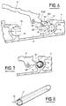
- FIG. 1 represents a truck, which comprises a platform 1 for transporting goods resting on the ground by means of its wheels 2.
- a tail lift 3 is coupled to the platform 1 by means of two deformable parallelograms 4, which allow adjusting the height of the platform 5 of the tail lift relative to the platform 1, while keeping the upper face of this platform horizontal and making however possible a slight inclination of this platform relative to the ground during of the platform support on the ground.
- the platform 5 has two stops each comprising a flap 6 which can either be contained in the plane of the upper face of the platform (the flap of one of the stops is shown in this first position), or d '' be projecting from the plane of the upper face of the platform (the flap of the other stop is shown in this second position).
- FIG. 2 represents the platform 5 bearing on the ground 7, the upper face 5A of the platform being slightly inclined relative to the ground surface, and a user 8 pushing a trolley 9 for handling goods on the platform, trolley provided with wheels 10, some of which bear on the edge 11 of the flap 6 projecting from the upper face 5A of the platform.
- the carriage 9 cannot inadvertently descend the inclined face 5A, the flap 6 preventing this movement.
- FIG. 3 represents the flap 6, in the configuration in which its upper face 6A is contained in the plane P of the upper face 5A of the platform 5 and in which said flap is entirely retracted inside a housing 13 provided for this purpose in the platform 5.
- Two bearings 14 and 15, of circular sections, are provided in the platform 5, inside the housing 13, and receive pivotally about their respective axes 14A, 15A, the bearing 14, a shutter shaft 16, integral with the shutter 6, with the interposition of a bearing 17, and, the bearing 15, an arm shaft 18, of which one arm 19 is integral with respect to the pivoting .
- the flap 6 and the arm 19 each have an eye 20,21, which allow the ends of a spring 22 to be hooked schematically by a dashed line.
- This spring can advantageously be constituted by a blade or a wire shaped as a W and be a compression spring which, in the assembly shown, tends to relax (to spread its ends).
- the line L20 / 21 which joins the eyes 20 and 21 and which constitutes the line of action of the restoring force developed by the spring 22, is arranged on a first side of the axis 14A of the pivoting of the flap 6, the force of return of the spring developing a pivoting torque on the flap 6, around the pivot axis 14, which tends to maintain said flap in its position, the lower face 6B of its free end being in abutment on the upper face of a rim 23 which comprises the housing 13.
- This arm 19 can therefore, at the will of the user, be placed in one of its two extreme positions shown, the first extreme position in FIG. 3, the arm 19 then being in abutment on a first abutment face 24 of the platform 5, which limits its pivoting in one direction , and, the second extreme position shown in Figure 4, the arm 19 being supported on a second abutment face 25 of the platform 5, which limits the pivoting in the other direction.
- the lever 12 can be tilted so as to place the arm 19 in its second extreme position in FIG. 4.
- the flap 6 has been shown in three different positions in FIG. 4: a position in solid lines, in which the plane R of the upper face 6A of the shutter makes a maximum angle A with the plane P passing through the upper face 5A of the platform 5; the position of FIG. 3 and an intermediate position, both in broken lines, the intermediate position being between that of FIG. 3 and that shown in solid lines in FIG. 4.
- the line L20 / 21 is arranged either on one side or on the other side of the pivot axis 14A of the flap 6, so that from the position in solid lines, similar to that, also in lines of Figure 4, in which the spring 22 tends to keep the flap projecting from the plane P, the foot 26 of a user can rotate the flap 6 to the position in broken lines, which is identical to that of FIG. 3, in which the spring 22 has the effect of maintaining the flap 6 so that its upper face 6A remains contained in the plane P.
- the flap 6 has its pivoting limited by pressing on an abutment face 27 of the platform 5.
- FIGS 6,7 and 8 illustrate the details of construction allowing the pivoting mounting of the shutter 6.
- the shutter shaft 16 is connected to the shutter 6 by a strip 28 of thickness E28, less than both the respective smallest dimensions of the shaft 16 and of the shutter 6.
- the shutter shaft 16 has a cylindrical face 16C and a flat 16B, the thickness of the shutter shaft, measured along a diameter perpendicular to the flat 16B, passing through the center 16A of the shutter shaft 16, being equal to E16.
- the bearing 14 has a longitudinal opening 29 of width E29.
- the length of a flap shaft 16 can, for example, be equal to 800 mm, the length of a pad 17 being considerably smaller: 80 mm for example.
- the housing 13 is made accessible only by cutting out the upper plate of the platform 5.
- the flap 6 is mounted as follows: the flap shaft 16 is presented opposite the opening 29 of the bearing 14, the thickness E16 substantially parallel to the opening 29, so that the flap shaft 16 can pass through said opening 29 and be introduced into the bearing 14; one or two pads 17 are then presented in front of a longitudinal end of said flap shaft 16 and bearing 14, and introduced into the space between these two parts, the opening 30 being of course arranged facing the strip 28 to allow it the passage. Note that the dimensions of both the length of the shutter shaft 16 and of the cushion 17 practically retained make possible the assembly which has just been defined.
- the wheel 10 presses on the upper face 6A of the flap 6, makes this flap 6 tilt from its projecting position to that of complete retraction in which the upper face 6A of the flap 6 is contained in the plane P Then, after passage of the wheel 10, the flap 6 automatically resumes its projecting position (in solid lines in FIG. 4), in which it constitutes a stop 11 for the wheels 10 of the carriage 9 (FIG. 2), which prevents any unwanted withdrawal of the carriage 9 from the platform 5.
Description
Certains véhicules, notamment des camions, sont munis de hayons élévateurs qui facilitent le chargement et le déchargement de chariots de manutention des marchandises transportées.Certain vehicles, notably trucks, are fitted with tail lifts which facilitate the loading and unloading of handling carts for the goods transported.
Les plus perfectionnés des hayons élévateurs connus comportent des butées, escamotables dans la plate-forme, qui permettent, bien entendu, en s'escamotant, le passage des roues des chariots aussi bien pendant les opérations de chargement que pendant celles de déchargement, et qui ont d'abord pour fonction première d'empêcher tout déplacement non désiré d'un chariot, initialement placé sur la plate-forme du hayon, hors de cette plate-forme.The most sophisticated of known tail lifts have stops, retractable in the platform, which allow, of course, by retracting, the passage of the wheels of the carriages both during loading operations and during those of unloading, and which firstly have the primary function of preventing any unwanted movement of a carriage, initially placed on the tailgate platform, out of this platform.
DE-A-2 757 763 selon le préambule de la revendication 1 représente un tel hayon, dont la ou les butées, attelées à des ressorts de rappel, sont maintenues, en permanence, soit en configuration d'escamotage dans la plate-forme, soit en saillie par rapport à la face supérieure de la plate-forme. Cette disposition est telle que, lorsque la plate-forme est en appui sur le sol et légèrement inclinée par rapport à celui-ci, l'utilisateur doit simultanément, au cours d'un chargement, pousser le chariot et commander l'escamotage de la butée pour bloquer les roues du chariot après passage sur la butée. Pendant cette opération, l'utilisateur est en appui et en déséquilibre sur un seul pied, avec risque d'accident.DE-A-2 757 763 according to the preamble of claim 1 represents such a tailgate, the abutment or stops of which, coupled to return springs, are maintained, permanently, either in retraction configuration in the platform, either projecting from the upper face of the platform. This arrangement is such that, when the platform is in contact with the ground and slightly inclined with respect to the latter, the user must simultaneously, during loading, push the carriage and control the retraction of the stop to lock the wheels of the carriage after passing over the stop. During this operation, the user is in support and unbalanced on one foot, with risk of accident.
L'invention entend remédier à cet inconvénient en concevant une butée qui, dans la configuration en saillie par rapport à la plate-forme, serait apte à s'escamoter automatiquement lors du passage de la roue d'un chariot pendant une phase de chargement du chariot sur la plate-forme et à reprendre automatiquement ladite configuration en saillie après passage de ladite roue, afin d'éviter tout déchargement accidentel dudit chariot.The invention intends to remedy this drawback by designing a stop which, in the protruding configuration relative to the platform, would be able to retract automatically during the passage of the wheel of a carriage during a loading phase of the carriage on the platform and to automatically resume said projecting configuration after passage of said wheel, in order to avoid any accidental unloading of said carriage.
L'invention est donc relative à un hayon élévateur attelé au plateau de transport d'un véhicule et comportant une plate-forme susceptible de constituer le support temporaire d'un chariot ou analogue muni d'organes de roulement ; une butée de maintien d'un tel chariot sur la plate-forme comprenant un volet, qui est monté pivotant, autour d'un axe de volet, par rapport à la plate-forme, qui comporte une lisière mobile, et, qui est susceptible d'occuper deux positions particulières par rapport à la plate-forme, une première position dans laquelle la face supérieure du volet est contenue dans le plan de la face supérieure de la plate-forme, et, une deuxième position dans laquelle la face supérieure du volet est décalée angulairement par rapport à la face supérieure de la plate-forme, ladite lisière mobile étant alors disposée en saillie par rapport à ladite face supérieure de la plate-forme ; et un organe élastique attelé entre la plate-forme et le volet et exerçant sur ledit volet une force de rappel dont l'effet, d'une part, dans la première position du volet, est de maintenir ledit volet dans sa première position, d'autre part, dans la deuxième position du volet, est de rappeler ledit volet dans sa deuxième position.The invention therefore relates to a tail lift coupled to the transport platform of a vehicle and comprising a platform capable of constituting the temporary support of a trolley or the like provided with rolling members; a stop for holding such a carriage on the platform comprising a flap, which is pivotally mounted, about a flap axis, relative to the platform, which has a movable edge, and which is capable to occupy two particular positions relative to the platform, a first position in which the upper face of the flap is contained in the plane of the upper face of the platform, and a second position in which the upper face of the flap is offset angularly with respect to the upper face of the platform, said movable selvedge then being arranged projecting with respect to said upper face of the platform; and an elastic member coupled between the platform and the flap and exerting on said flap a restoring force whose effect, on the one hand, in the first position of the flap, is to maintain said flap in its first position, d on the other hand, in the second position of the flap, is to recall said flap in its second position.
Selon l'invention, les dispositions suivantes sont adoptées : a) l'organe élastique est attelé à la plate-forme par l'intermédiaire d'un bras, qui est monté mobile par rapport à la plate-forme entre deux positions extrêmes et qui est donc susceptible de modifier la position de l'attache de l'organe élastique par rapport à la plate-forme ; b) dans la première position du volet, d'une part, dans sa première position extrême, le bras a placé ladite attache de l'organe élastique de manière que la ligne joignant les points d'attache de l'organe élastique sur le bras et sur le volet soit disposée d'un premier côté de l'axe de pivotement du volet par rapport à la plate-forme et que l'effet de rappel de l'organe élastique sur le volet tende à maintenir ledit volet dans sa première position, d'autre part, dans sa deuxième position extrême, le bras a placé ladite attache de l'organe élastique de manière que la ligne joignant les points d'attache de l'organe élastique sur le bras et sur le volet soit disposée du côté de l'axe de pivotement du volet par rapport à la plate-forme opposé audit premier côté et qu'alors l'effet de rappel de l'organe élastique sur le volet tende à pousser ledit volet vers sa deuxième position ; et, c) ledit bras est attelé à une commande volontaire de sélection de ses deux positions extrêmes, apte à le placer, à la volonté d'un utilisateur, dans l'une ou l'autre desdites deux positions extrêmes.According to the invention, the following arrangements are adopted: a) the elastic member is coupled to the platform by means of an arm, which is mounted movable relative to the platform between two extreme positions and which is therefore likely to modify the position of the attachment of the elastic member relative to the platform; b) in the first position of the flap, on the one hand, in its first extreme position, the arm has placed said attachment of the elastic member so that the line joining the attachment points of the elastic member on the arm and on the flap is disposed on a first side of the pivot axis of the flap relative to the platform and that the return effect of the elastic member on the flap tends to maintain said flap in its first position , on the other hand, in its second extreme position, the arm has placed said attachment of the elastic member so that the line joining the attachment points of the elastic member on the arm and on the flap is disposed on the side of the pivot axis of the flap relative to the platform opposite to said first side and that then the return effect of the elastic member on the flap tends to push said flap towards its second position; and, c) said arm is coupled to a voluntary command to select its two extreme positions, able to place it, at the will of a user, in one or the other of said two extreme positions.
Les avantageuses dispositions suivantes sont en outre de préférence adoptées :
- le bras est monté à pivotement par rapport à la plate-forme ;
- le bras est solidaire d'un arbre de bras qui en réalise le montage à pivotement, cependant que la commande de sélection de position du bras comprend au moins un levier à deux positions, qui est solidaire dudit bras vis-à-vis du pivotement ;
- le levier est constitué par un boulon, qui est vissé dans l'arbre de bras ;
- l'organe élastique est constitué par un ressort de compression ;
- la plate-forme est réalisée en un matériau extrudé, tel qu'un alliage d'aluminium, les logements des arbres réalisant les pivotements du volet et du bras par rapport à la plate-forme étant formés lors de l'extrusion de ladite plate-forme ;
- le volet est solidaire d'un arbre de volet, dont une dimension transversale externe est au plus égale à celle d'une ouverture longitudinale que comporte un logement d'arbre ménagé dans la plate-forme, ce qui permet l'introduction dudit arbre de volet dans ledit logement, cependant qu'un coussinet, ayant une forme correspondant à l'espace compris entre l'arbre de volet et son logement, est introduit, par une extrémité longitudinale de l'arbre de volet, dans ledit espace et placé entre ledit arbre de volet et son logement ;
- l'arbre de volet a une face cylindrique circulaire, dont le diamètre est supérieur à la largeur de l'ouverture longitudinale du logement et qui est munie d'un méplat, la distance entre le méplat et la face cylindrique opposée de l'arbre de volet étant au plus égale à ladite largeur de l'ouverture longitudinale.
- the arm is pivotally mounted relative to the platform;
- the arm is integral with an arm shaft which carries out the pivoting assembly thereof, while the arm position selection control comprises at least one lever with two positions, which is integral with the said arm with respect to the pivoting;
- the lever consists of a bolt, which is screwed into the arm shaft;
- the elastic member is constituted by a compression spring;
- the platform is made of an extruded material, such as an aluminum alloy, the housings of the shafts performing the pivoting of the flap and of the arm relative to the platform being formed during the extrusion of said platform shape;
- the shutter is integral with a shutter shaft, an external transverse dimension of which is at most equal to that of a longitudinal opening that comprises a shaft housing formed in the platform, which allows the introduction of said shaft shutter in said housing, while a bearing, having a shape corresponding to the space between the shutter shaft and its housing, is introduced, by a longitudinal end of the shutter shaft, into said space and placed between said shutter shaft and its housing;
- the flap shaft has a circular cylindrical face, the diameter of which is greater than the width of the longitudinal opening in the housing and which is provided with a flat, the distance between the flat and the opposite cylindrical face of the flap being at most equal to said width of the longitudinal opening.
L'avantage principal de l'invention est de réaliser un hayon élévateur muni d'une butée qui peut être placée dans les configurations classiques, mais qui, en outre, peut s'effacer sous la pression d'une roue de chariot lors d'un chargement et reprendre automatiquement sa configuration en saillie par rapport à la plate-forme après passage de la roue. Cette automaticité des deux déplacements de la butée (escamotage et remise en saillie) supprime les manoeuvres hasardeuses antérieures et les risques d'accidents correspondants.The main advantage of the invention is to provide a tail lift fitted with a stop which can be placed in conventional configurations, but which, moreover, can be erased under the pressure of a carriage wheel when a load and automatically resume its projecting configuration relative to the platform after passing the wheel. This automaticity of the two movements of the stop (retraction and resurface) eliminates previous hazardous maneuvers and the corresponding risk of accidents.
L'invention sera mieux comprise, et des caractéristiques secondaires et leurs avantages apparaîtront au cours de la description d'une réalisation donnée ci-dessous à titre d'exemple.The invention will be better understood, and secondary characteristics and their advantages will appear during the description of an embodiment given below by way of example.
Il est entendu que la description et les dessins ne sont donnés qu'à titre indicatif et non limitatif.It is understood that the description and the drawings are given for information only and are not limiting.
Il sera fait référence aux dessins annexés, dans lesquels :
- la figure 1 est une vue perspective de la partie arrière d'un camion muni d'un hayon élévateur conforme à l'invention ;
- la figure 2 est une vue en élévation du hayon élévateur représenté sur la figure 1, pendant le chargement d'un chariot ;
- les figures 3,4 et 5 sont des coupes longitudinales du hayon élévateur de la figure 2 illustrant trois configurations distinctes de ce hayon élévateur ;
- les figures 6 et 7 sont des coupes longitudinales du hayon élévateur de la figure 2 mettant en évidence un détail de sa réalisation, dans deux configurations de montage ; et,
- la figure 8 est une vue perspective d'un élément du montage des figures 6 et 7.
- Figure 1 is a perspective view of the rear part of a truck with a tail lift according to the invention;
- Figure 2 is an elevational view of the tail lift shown in Figure 1, during the loading of a carriage;
- Figures 3,4 and 5 are longitudinal sections of the tail lift of Figure 2 illustrating three distinct configurations of this tail lift;
- Figures 6 and 7 are longitudinal sections of the tail lift of Figure 2 showing a detail of its embodiment, in two mounting configurations; and,
- FIG. 8 is a perspective view of an element of the assembly of FIGS. 6 and 7.
La figure 1 représente un camion, qui comporte un plateau 1 de transport des marchandises reposant sur le sol par l'intermédiaire de ses roues 2. Un hayon élévateur 3 est attelé au plateau 1 par l'intermédiaire de deux parallélogrammes déformables 4, qui permettent le réglage de la hauteur de la plate-forme 5 du hayon élévateur par rapport au plateau 1, tout en maintenant horizontale la face supérieure de cette plate-forme et en rendant cependant possible une légère inclinaison de cette plate-forme par rapport au sol lors de l'appui de la plate-forme sur le sol. La plate-forme 5 comporte deux butées comprenant chacune un volet 6 susceptible, soit d'être contenu dans le plan de la face supérieure de la plate-forme (le volet d'une des butées est représenté dans cette première position), soit d'être disposé en saillie par rapport au plan de la face supérieure de la plate-forme (le volet de l'autre butée est représenté dans cette deuxième position).FIG. 1 represents a truck, which comprises a platform 1 for transporting goods resting on the ground by means of its
La figure 2 représente la plate-forme 5 en appui sur le sol 7, la face supérieure 5A de la plate-forme étant légèrement inclinée par rapport à la surface du sol, et un utilisateur 8 poussant un chariot 9 de manutention de marchandises sur la plate-forme, chariot muni de roues 10, dont certaines sont en appui sur la lisière 11 du volet 6 disposé en saillie par rapport à la face supérieure 5A de la plate-forme. Dans cette configuration, le chariot 9 ne peut pas redescendre par inadvertance la face inclinée 5A, le volet 6 interdisant ce déplacement.FIG. 2 represents the
A noter la présence, au-dessus de la face supérieure de la plate-forme 5, de deux leviers 12 (figure 1), dont la fonction sera précisée ultérieurement.Note the presence, above the upper face of the
La figure 3 représente le volet 6, dans la configuration dans laquelle sa face supérieure 6A est contenue dans le plan P de la face supérieure 5A de la plate-forme 5 et dans laquelle ledit volet est entièrement escamoté à l'intérieur d'un logement 13 prévu à cet effet dans la plate-forme 5. Deux paliers 14 et 15, de sections circulaires, sont ménagés dans la plate-forme 5, à l'intérieur du logement 13, et reçoivent à pivotement autour de leurs axes respectifs 14A,15A, le palier 14, un arbre de volet 16, solidaire du volet 6, avec interposition d'un coussinet 17, et, le palier 15, un arbre de bras 18, dont un bras 19 est solidaire vis-à-vis du pivotement.FIG. 3 represents the
Le volet 6 et le bras 19 comportent chacun un oeil 20,21, qui permettent l'accrochage des extrémités d'un ressort 22 schématisé par un trait mixte. Ce ressort peut avantageusement être constitué par une lame ou un fil conformé en un W et être un ressort de compression qui, dans le montage représenté, a tendance à se détendre (à écarter ses extrémités).The
Dans la configuration de la figure 3, la ligne L20/21, qui joint les yeux 20 et 21 et qui constitue la ligne d'action de la force de rappel développée par le ressort 22, est disposée d'un premier côté de l'axe 14A du pivotement du volet 6, la force de rappel du ressort développant un couple de pivotement sur le volet 6, autour de l'axe de pivotement 14, qui tend à maintenir ledit volet dans sa position, la face inférieure 6B de son extrémité libre étant en appui sur la face supérieure d'un rebord 23 que comporte le logement 13.In the configuration of FIG. 3, the line L20 / 21, which joins the
Un levier 12, constitué par un boulon, est vissé dans l'arbre de bras 18, en est ainsi rendu solidaire et constitue une commande volontaire du pivotement du bras 19. Ce bras 19 peut donc, à la volonté de l'utilisateur, être placé dans l'une de ses deux positions extrêmes représentées, la première position extrême sur la figure 3, le bras 19 étant alors en appui sur une première face de butée 24 de la plate-forme 5, qui en limite le pivotement dans un sens, et, la deuxième position extrême représentée sur la figure 4, le bras 19 étant en appui sur une deuxième face de butée 25 de la plate-forme 5, qui en limite le pivotement dans l'autre sens.A
Le levier 12 peut être basculé de manière à placer le bras 19 dans sa deuxième position extrême de la figure 4. Le volet 6 a été représenté dans trois positions différentes sur la figure 4 : une position en traits continus, dans laquelle le plan R de la face supérieure 6A du volet fait un angle A maximal avec le plan P passant par la face supérieure 5A de la plate-forme 5 ; la position de la figure 3 et une position intermédiaire, toutes deux en traits interrompus, la position intermédiaire étant comprise entre celle de la figure 3 et celle représentée en traits continus sur la figure 4.The
Dans toutes ces positions, compte tenu de la position de l'oeil 21, nouvelle par rapport à celle représentée sur la figure 3, la ligne L20/21 est toujours disposée du côté de l'axe 14A du pivotement du volet 6 qui est opposé à celui de la figure 3, c'est-à-dire dans une configuration dans laquelle le couple de rappel développé par le ressort 22 sur le volet 6 tend à pousser ce volet 6 vers la position en traits continus, ou à l'y maintenir. Dans cette position, la lisière 11 est en saillie par rapport au plan P. La roue 10 d'un chariot a été représentée, sur la figure 4, au moment où elle a déjà repoussé le volet 6 de sa position en traits continus jusqu'à sa position intermédiaire.In all these positions, taking into account the position of the
Il est enfin possible, à partir de la configuration de la figure 4, de replacer le bras 19 dans sa première position extrême (celle de la figure 3). La ligne L20/21 est disposée soit d'un côté, soit de l'autre côté de l'axe de pivotement 14A du volet 6, de sorte qu'à partir de la position en traits continus, analogue à celle, également en traits continus de la figure 4, dans laquelle le ressort 22 tend à maintenir le volet en saillie par rapport au plan P, le pied 26 d'un utilisateur peut faire pivoter le volet 6 jusqu'à la position en traits interrompus, qui est identique à celle de la figure 3, dans laquelle le ressort 22 a pour effet de maintenir le volet 6 de manière que sa face supérieure 6A reste contenue dans le plan P.It is finally possible, from the configuration of FIG. 4, to replace the
A noter qu'en position de saillie complète (angle A de la figure 4), le volet 6 a son pivotement limité par appui sur une face de butée 27 de la plate-forme 5.Note that in the fully projecting position (angle A in FIG. 4), the
Les figures 6,7 et 8 illustrent les détails de réalisation permettant le montage à pivotement du volet 6. L'arbre de volet 16 est relié au volet 6 par une bande 28 d'épaisseur E28, inférieure à la fois aux plus petites dimensions respectives de l'arbre 16 et du volet 6. L'arbre de volet 16 comporte une face cylindrique 16C et un méplat 16B, l'épaisseur de l'arbre de volet, mesurée suivant un diamètre perpendiculaire au méplat 16B, passant par le centre 16A de l'arbre de volet 16, étant égale à E16. Le palier 14 présente une ouverture longitudinale 29 de largeur E29.Figures 6,7 and 8 illustrate the details of construction allowing the pivoting mounting of the
Les diverses dimensions présentent des valeurs relatives, tel que précisé ci-après :
- le diamètre D14 du
palier 14 est supérieur au diamètre D16 de l'arbre de volet 16 (D14 >D 16), de sorte qu'après introduction de l'arbre devolet 16 dans lepalier 14, un espace existe entre ces deux pièces et est occupé par le coussinet 17 (figure 7) ; - l'épaisseur E16 est inférieure à la largeur E29 (E16<E29), ce qui permet l'introduction de l'arbre de
volet 16 à l'intérieur de l'espace délimité par lepalier 14 ; - le coussinet 17 comporte une ouverture longitudinale 30, dont la largeur E30 est inférieure au diamètre D16 (E30<D16)de manière que l'arbre de volet 16, une fois introduit dans le coussinet 17, ne puisse pas s'en échapper ;
- enfin, les largeurs E29 et E30 sont, chacune, supérieures à l'épaisseur E28 de la bande 28 (E29>E28 et E30>E28), ce qui permet bien entendu le passage de la bande 28 à travers les ouvertures 29
et 30.
- the diameter D14 of the
bearing 14 is greater than the diameter D16 of the flap shaft 16 (D14> D 16), so that after introduction of theflap shaft 16 in thebearing 14, a space exists between these two parts and is occupied by the pad 17 (Figure 7); - the thickness E16 is less than the width E29 (E16 <E29), which allows the introduction of the
flap shaft 16 inside the space delimited by thebearing 14; - the
pad 17 has alongitudinal opening 30, whose width E30 is less than the diameter D16 (E30 <D16) so that theflap shaft 16, once introduced into thebearing 17, cannot escape from it; - finally, the widths E29 and E30 are each greater than the thickness E28 of the strip 28 (E29> E28 and E30> E28), which of course allows the passage of the
strip 28 through theopenings
Il doit en outre être noté que la longueur d'un arbre de volet 16 peut, par exemple, être égale à 800 mm, la longueur d'un coussinet 17 étant considérablement plus petite : 80 mm par exemple. Par ailleurs, pour obtenir les paliers 14 et 15, et plus généralement la plate-forme 5, il est pratique de procéder par extrusion, d'un alliage d'aluminium par exemple. Dans ces conditions, le logement 13 n'est rendu accessible que par découpe de la plaque supérieure de la plate-forme 5.It should also be noted that the length of a
En tenant compte de ces indications, le montage du volet 6 est réalisé comme suit : l'arbre de volet 16 est présenté en regard de l'ouverture 29 du palier 14, l'épaisseur E16 sensiblement parallèle à l'ouverture 29, de sorte que l'arbre de volet 16 peut traverser ladite ouverture 29 et être introduit dans le palier 14 ; un ou deux coussinets 17 sont alors présentés devant une extrémité longitudinale desdits arbre de volet 16 et palier 14, et introduits dans l'espace compris entre ces deux pièces, l'ouverture 30 étant bien entendu disposée en regard de la bande 28 pour en permettre le passage. A noter que les dimensions aussi bien de longueurs de l'arbre de volet 16 que du coussinet 17 pratiquement retenues rendent possible le montage qui vient d'être défini.Taking these indications into account, the
En variante, en remplacement de l'arbre de volet 16 muni de son méplat 16B, il serait possible de choisir un arbre de volet 16, sans méplat, ayant un diamètre D16 suffisamment petit pour passer à travers l'ouverture 29, tout en restant bien entendu supérieur à l'ouverture 30 (D16<E29 et D16>E30). Cette variante conduit par contre à diminuer la valeur du diamètre D16 par rapport à la première réalisation décrite, donc, également à augmenter l'épaisseur du coussinet 17 pour combler l'espace compris entre le palier 14 et l'arbre de volet 16.Alternatively, replacing the
Le fonctionnement a déjà été suggéré précédemment et peut donc être brièvement précisé.Operation has already been suggested previously and can therefore be briefly explained.
Dans la configuration de la figure 3, le boulon 12 ayant été placé selon la volonté de l'utilisateur, dans sa première position, ce qui a provoqué la mise en place de l'arbre de bras 18 également dans sa première position extrême, l'effort de rappel du ressort 22 a un effet de maintien du volet 6 dans sa position, qui est donc une position stable, dans laquelle, par exemple, l'utilisateur peut retirer librement, par roulage sur le plan P, un chariot 9 hors de la plate-forme 5.In the configuration of FIG. 3, the
Dans les configurations de la figure 4, l'utilisateur a placé le boulon 12 dans sa deuxième position, et par suite également l'arbre de bras 18 dans sa deuxième position extrême. Quelle que soit la position du volet 6, l'effet du ressort 22 est, soit de rappeler le volet 6 vers sa position entièrement en saillie (en traits continus), soit de maintenir ce volet dans cette position. Ce sont les configurations correspondant par exemple au chargement, par roulage, d'un chariot 9 du sol 7 sur la plate-forme 5. Sans que l'utilisateur n'ait d'autre nécessité que celle de pousser le chariot 9 sur la plate-forme 5, la roue 10 appuie sur la face supérieure 6A du volet 6, fait basculer ce volet 6 depuis sa position en saillie jusqu'à celle d'escamotage complet dans laquelle la face supérieure 6A du volet 6 est contenue dans le plan P. Puis, après passage de la roue 10, le volet 6 reprend automatiquement sa position en saillie (en traits continus sur la figure 4), dans laquelle il constitue une butée 11 pour les roues 10 du chariot 9 (figure 2), ce qui évite tout retrait non désiré du chariot 9 hors de la plate-forme 5.In the configurations of Figure 4, the user has placed the
Quand enfin l'utilisateur, à partir de l'une des configurations de la figure 4 souhaite retrouver celle, stable, de la figure 3, il lui suffit, à partir des configurations de la figure 4, de déplacer le boulon 12 de sa deuxième vers sa première position, d'obtenir ainsi la configuration de la figure 5 dans laquelle l'arbre de bras 18 est placé dans sa première position extrême, et de faire pivoter le volet 6 jusqu'à sa mise en place dans la configuration de la figure 3, dans laquelle la face supérieure 6A du volet 6 est contenue dans le plan P. Pour ce faire, l'utilisateur peut, par exemple, appuyer avec son pied 26.When finally the user, from one of the configurations of FIG. 4 wishes to find that, stable, of FIG. 3, it suffices for him, from the configurations of FIG. 4, to move the
Ainsi, les manutentions de chariots sont simples, effectuées en toute sécurité, et n'exigent pas que l'utilisateur soit en même temps un acrobate apte, en se tenant debout sur un pied, à pousser le chariot 9, et, simultanément à commander avec l'autre pied la position du volet 6, ce qui était le cas avec les hayons élévateurs connus antérieurement.Thus, the handling of trolleys is simple, carried out safely, and does not require the user to be at the same time an acrobat capable, standing on one foot, of pushing the
Il reste conforme à l'invention de réaliser le déplacement du bras 19 par coulissement en remplacement du pivotement décrit ci-avant.It remains in accordance with the invention to move the
Claims (8)
- Lifting tailgate coupled to the transport bed (1) of a vehicle and comprising:- a platform (5) capable of forming a temporary support for a trolley (9) or the like provided with running gear (10);- a stop for keeping such a trolley on the platform comprising a flap (6) which is mounted for pivoting (14-16) about a flap axis (14A) relative to the platform (5), which comprises a movable edge (11) and which is capable of occupying two particular positions relative to the platform, a first position (Fig. 3) in which the upper surface (6A) of the flap (6) is contained in the plane (P) of the upper surface (5A) of the platform (5), and a second position (Fig. 4) in which the upper surface (6A) of the flap (6) is angularly offset (A) relative to the upper surface (5A) of the platform (5), said movable edge (11) then projecting from said upper surface (5A) of the platform (5);- a resilient member (22) coupled between the platform and the flap (6) and exerting on said flap a return force of which the effect, on the one hand in the first position of the flap, is to keep said flap in its first position, and on the other hand in the second position of the flap, is to return said flap to its second position,characterised in that:a) the resilient member (22) is coupled to the platform by means of an arm (19) which is mounted for movement relative to the platform between two end positions and which is therefore capable of modifying the position of the attachment (21) of the resilient member (22) relative to the platform (5);b) in the first position of the flap (6), on the one hand in its first end position (Fig. 3), the arm (19) has placed said attachment (21) of the resilient member (22) so that the line (L20/21) joining the points of attachment (21-20) of the resilient member (22) to the arm (19) and to the flap (6) is arranged on a first side of the pivot axis (14A) of the flap (6) relative to the platform and so that the return effect of the resilient member on the flap biases said flap into its first position, and on the other hand in its second end position (Fig. 4), the arm (19) has placed said attachment (21) of the resilient member so that the line (L20/21) joining the points of attachment (21-20) of the resilient member to the arm (19) and to the flap (6) is arranged on the side of the pivot axis (14A) of the flap (6) relative to the platform opposite said first side and so that the return effect of the resilient member on the flap then biases said flap into its second position; andc) said arm (19) is coupled to a voluntary control means (12) for selecting its two end positions, adapted to place it as the user wishes in either of said two end positions.
- Lifting tailgate according to claim 1, characterised in that the arm (19) is mounted for pivoting (15A) relative to the platform (5).
- Lifting tailgate according to claim 2, characterised in that the arm (19) is rigidly connected to an arm shaft (18) which provides the pivotable mounting thereof, but in that the control means for selecting the position of the arm comprises at least one lever (12) with two positions, which is rigidly connected to said arm with respect to pivoting.
- Lifting tailgate according to claim 3, characterised in that the lever consists of a bolt (12) which is screwed into the shaft of the arm (19).
- Lifting tailgate according to any of claims 1 to 4, characterised in that the resilient member consists of a compression spring (22).
- Lifting tailgate according to any of claims 1 to 5, characterised in that the platform (5) is made of an extruded material such as an aluminium alloy, the receptacles (14-15) of the shafts which carry out pivoting of the flap (6) and arm (19) relative to the platform (5) being formed during extrusion of said platform.
- Lifting tailgate according to any of claims 1 to 6, characterised in that the flap (6) is rigidly connected to a flap shaft (16) of which an outside transverse dimension (E16) is at most equal to that (E29) of a longitudinal opening (29) which a shaft receptacle (14) formed in the platform (5) comprises, which allows the introduction of said flap shaft (16) into said receptacle (14), but in that a bearing bush (17) having a shape corresponding to the space between the flap shaft and its receptacle is introduced, by a longitudinal end of the flap shaft (16), into said space and placed between said flap shaft (16) and its receptacle (14).
- Lifting tailgate according to claim 7, characterised in that the flap shaft (16) has a circular cylindrical surface (16C) of which the diameter (D16) is greater than the width (E29) of the longitudinal opening (29) of the receptacle (14) and which is provided with a flattened portion (16B), the distance (E16) between the flattened portion (16B) and the opposed cylindrical surface (16C) of the flap- shaft (16) being at most equal to said width (E29) of the longitudinal opening.
Applications Claiming Priority (2)
| Application Number | Priority Date | Filing Date | Title |
|---|---|---|---|
| FR9012132A FR2667282B1 (en) | 1990-10-02 | 1990-10-02 | LIFT HATCH INCLUDING A STOP HOLDER OF A TROLLEY ON ITS PLATFORM. |
| FR9012132 | 1990-10-02 |
Publications (2)
| Publication Number | Publication Date |
|---|---|
| EP0480791A1 EP0480791A1 (en) | 1992-04-15 |
| EP0480791B1 true EP0480791B1 (en) | 1994-01-12 |
Family
ID=9400859
Family Applications (1)
| Application Number | Title | Priority Date | Filing Date |
|---|---|---|---|
| EP19910402573 Expired - Lifetime EP0480791B1 (en) | 1990-10-02 | 1991-09-26 | Liftable loading tailgate with a stop for locking a carriage on its platform |
Country Status (3)
| Country | Link |
|---|---|
| EP (1) | EP0480791B1 (en) |
| DE (1) | DE69101000T2 (en) |
| FR (1) | FR2667282B1 (en) |
Cited By (4)
| Publication number | Priority date | Publication date | Assignee | Title |
|---|---|---|---|---|
| US5683221A (en) * | 1994-07-11 | 1997-11-04 | Maxon Industries, Inc. | Lift platform with cart stop |
| EP1318045A1 (en) * | 2001-12-05 | 2003-06-11 | Peter Maier Leichtbau GmbH | Pivoting safety flap for a lifting tailgate |
| EP1336534A1 (en) * | 2002-02-19 | 2003-08-20 | Peter Maier Leichtbau GmbH | Wheel chock device |
| WO2010138732A1 (en) * | 2009-05-29 | 2010-12-02 | Maxon Industries, Inc. | Cart stop |
Family Cites Families (2)
| Publication number | Priority date | Publication date | Assignee | Title |
|---|---|---|---|---|
| DE7637158U1 (en) * | 1976-11-26 | 1977-05-18 | Toussaint & Hess Hydraulische Hebezeugfabrik Gmbh, 4000 Duesseldorf | Device for securing a load pick-up |
| DE8632891U1 (en) * | 1986-12-09 | 1987-06-19 | Aluminium Walzwerke Singen Gmbh, 7700 Singen, De |
-
1990
- 1990-10-02 FR FR9012132A patent/FR2667282B1/en not_active Expired - Fee Related
-
1991
- 1991-09-26 EP EP19910402573 patent/EP0480791B1/en not_active Expired - Lifetime
- 1991-09-26 DE DE1991601000 patent/DE69101000T2/en not_active Expired - Fee Related
Cited By (5)
| Publication number | Priority date | Publication date | Assignee | Title |
|---|---|---|---|---|
| US5683221A (en) * | 1994-07-11 | 1997-11-04 | Maxon Industries, Inc. | Lift platform with cart stop |
| EP1318045A1 (en) * | 2001-12-05 | 2003-06-11 | Peter Maier Leichtbau GmbH | Pivoting safety flap for a lifting tailgate |
| EP1336534A1 (en) * | 2002-02-19 | 2003-08-20 | Peter Maier Leichtbau GmbH | Wheel chock device |
| US8382420B2 (en) | 2007-02-02 | 2013-02-26 | Maxon Industries, Inc. | Cart stop |
| WO2010138732A1 (en) * | 2009-05-29 | 2010-12-02 | Maxon Industries, Inc. | Cart stop |
Also Published As
| Publication number | Publication date |
|---|---|
| FR2667282B1 (en) | 1995-08-18 |
| FR2667282A1 (en) | 1992-04-03 |
| EP0480791A1 (en) | 1992-04-15 |
| DE69101000T2 (en) | 1994-05-05 |
| DE69101000D1 (en) | 1994-02-24 |
Similar Documents
| Publication | Publication Date | Title |
|---|---|---|
| EP1349769B1 (en) | Folding bicycle | |
| EP0252851B1 (en) | Foldable cart meant for in particular the transport of a bag for golf clubs | |
| EP0284532A1 (en) | Self-locking hinged chuck for immobilizing a motor vehicle on a loading ramp | |
| WO2010000987A1 (en) | Foldable stroller | |
| EP0389378B1 (en) | Vehicle loading platform and method of using same | |
| EP3755575B1 (en) | Tiltable trailer comprising mechanical actuation means and high-position locking means | |
| EP0480791B1 (en) | Liftable loading tailgate with a stop for locking a carriage on its platform | |
| EP0319436B1 (en) | Device for lowering the rear part of a road vehicle until it reaches ground level | |
| EP0296939B1 (en) | Armrest with two stable positions located between the front seats of automotive vehicles | |
| FR2641743A1 (en) | Vehicle fitted out to be equipped with an interchangeable tool and tool intended to equip such a vehicle | |
| EP0322299B1 (en) | Carrier for the spare wheel of a motor vehicle | |
| EP0330556B1 (en) | Rotatable display unit for a motor vehicle | |
| EP1495994B1 (en) | Mobile refuse collecter | |
| FR2908092A1 (en) | Heavy object e.g. motor cycle, loading and unloading device for e.g. trailer, has guiding unit guiding ramp between two positions and bringing back ramp above floor, when ramp reaches loading/unloading position | |
| WO1994011229A1 (en) | Pallet carrying trolley | |
| FR2500797A1 (en) | Caster wheel for hand cart or trolley - has wheel locking lever mounted on fork changing suspension axis to prevent involuntary unlocking | |
| WO2008145879A1 (en) | Sun shade for automobile | |
| FR2728861A1 (en) | External mounting for motor vehicle spare wheel | |
| EP3792143A1 (en) | Wheelbarrow provided with a pivoting gripping assembly | |
| FR2838098A1 (en) | Retractable stabilizer device for motorcycle comprises cylindrical tube serving as bearing for rotation of stabilizer which comprises shaft rotating freely in tube with ends outside tube having perpendicular arms with end castor | |
| CA1302335C (en) | Drive system for trolleys along a rail, and process for its application | |
| FR2919825A1 (en) | Sun visor for motor vehicle, has connection mechanism with differential friction units generating friction when movable extension structure is displaced towards deployed position, where friction is less during retracted position | |
| FR2765844A1 (en) | Wedge for motor vehicle on railway wagon | |
| FR2815010A1 (en) | FOLDING CYCLE | |
| FR2530555A1 (en) | Current wiper contact for electric trolley bus |
Legal Events
| Date | Code | Title | Description |
|---|---|---|---|
| PUAI | Public reference made under article 153(3) epc to a published international application that has entered the european phase |
Free format text: ORIGINAL CODE: 0009012 |
|
| AK | Designated contracting states |
Kind code of ref document: A1 Designated state(s): AT BE DE ES GB NL SE |
|
| 17P | Request for examination filed |
Effective date: 19920808 |
|
| 17Q | First examination report despatched |
Effective date: 19930611 |
|
| RBV | Designated contracting states (corrected) |
Designated state(s): BE DE GB |
|
| GRAA | (expected) grant |
Free format text: ORIGINAL CODE: 0009210 |
|
| AK | Designated contracting states |
Kind code of ref document: B1 Designated state(s): BE DE GB |
|
| REF | Corresponds to: |
Ref document number: 69101000 Country of ref document: DE Date of ref document: 19940224 |
|
| GBT | Gb: translation of ep patent filed (gb section 77(6)(a)/1977) |
Effective date: 19940203 |
|
| PGFP | Annual fee paid to national office [announced via postgrant information from national office to epo] |
Ref country code: BE Payment date: 19941012 Year of fee payment: 4 |
|
| PLBE | No opposition filed within time limit |
Free format text: ORIGINAL CODE: 0009261 |
|
| STAA | Information on the status of an ep patent application or granted ep patent |
Free format text: STATUS: NO OPPOSITION FILED WITHIN TIME LIMIT |
|
| 26N | No opposition filed | ||
| PG25 | Lapsed in a contracting state [announced via postgrant information from national office to epo] |
Ref country code: GB Effective date: 19950926 |
|
| PG25 | Lapsed in a contracting state [announced via postgrant information from national office to epo] |
Ref country code: BE Effective date: 19950930 |
|
| BERE | Be: lapsed |
Owner name: S.A. HYDRIS Effective date: 19950930 |
|
| GBPC | Gb: european patent ceased through non-payment of renewal fee |
Effective date: 19950926 |
|
| PGFP | Annual fee paid to national office [announced via postgrant information from national office to epo] |
Ref country code: DE Payment date: 20011017 Year of fee payment: 11 |
|
| PG25 | Lapsed in a contracting state [announced via postgrant information from national office to epo] |
Ref country code: DE Free format text: LAPSE BECAUSE OF NON-PAYMENT OF DUE FEES Effective date: 20030401 |