EP0479705A2 - Befestigungselement für genormte Gestellaufbauten - Google Patents
Befestigungselement für genormte Gestellaufbauten Download PDFInfo
- Publication number
- EP0479705A2 EP0479705A2 EP91500070A EP91500070A EP0479705A2 EP 0479705 A2 EP0479705 A2 EP 0479705A2 EP 91500070 A EP91500070 A EP 91500070A EP 91500070 A EP91500070 A EP 91500070A EP 0479705 A2 EP0479705 A2 EP 0479705A2
- Authority
- EP
- European Patent Office
- Prior art keywords
- arms
- clip
- parts
- head
- shank
- Prior art date
- Legal status (The legal status is an assumption and is not a legal conclusion. Google has not performed a legal analysis and makes no representation as to the accuracy of the status listed.)
- Withdrawn
Links
- 230000000903 blocking effect Effects 0.000 claims description 3
- 238000003780 insertion Methods 0.000 claims description 3
- 230000037431 insertion Effects 0.000 claims description 3
- 239000000463 material Substances 0.000 claims description 3
- 239000000470 constituent Substances 0.000 abstract description 2
- 230000008878 coupling Effects 0.000 description 3
- 238000010168 coupling process Methods 0.000 description 3
- 238000005859 coupling reaction Methods 0.000 description 3
- 238000006073 displacement reaction Methods 0.000 description 1
- 238000012423 maintenance Methods 0.000 description 1
- 239000002184 metal Substances 0.000 description 1
- 230000004048 modification Effects 0.000 description 1
- 238000012986 modification Methods 0.000 description 1
- 238000009423 ventilation Methods 0.000 description 1
Images


Classifications
-
- F—MECHANICAL ENGINEERING; LIGHTING; HEATING; WEAPONS; BLASTING
- F16—ENGINEERING ELEMENTS AND UNITS; GENERAL MEASURES FOR PRODUCING AND MAINTAINING EFFECTIVE FUNCTIONING OF MACHINES OR INSTALLATIONS; THERMAL INSULATION IN GENERAL
- F16B—DEVICES FOR FASTENING OR SECURING CONSTRUCTIONAL ELEMENTS OR MACHINE PARTS TOGETHER, e.g. NAILS, BOLTS, CIRCLIPS, CLAMPS, CLIPS OR WEDGES; JOINTS OR JOINTING
- F16B5/00—Joining sheets or plates, e.g. panels, to one another or to strips or bars parallel to them
- F16B5/06—Joining sheets or plates, e.g. panels, to one another or to strips or bars parallel to them by means of clamps or clips
- F16B5/0607—Joining sheets or plates, e.g. panels, to one another or to strips or bars parallel to them by means of clamps or clips joining sheets or plates to each other
- F16B5/0621—Joining sheets or plates, e.g. panels, to one another or to strips or bars parallel to them by means of clamps or clips joining sheets or plates to each other in parallel relationship
- F16B5/065—Joining sheets or plates, e.g. panels, to one another or to strips or bars parallel to them by means of clamps or clips joining sheets or plates to each other in parallel relationship the plates being one on top of the other and distanced from each other, e.g. by using protrusions to keep contact and distance
-
- F—MECHANICAL ENGINEERING; LIGHTING; HEATING; WEAPONS; BLASTING
- F16—ENGINEERING ELEMENTS AND UNITS; GENERAL MEASURES FOR PRODUCING AND MAINTAINING EFFECTIVE FUNCTIONING OF MACHINES OR INSTALLATIONS; THERMAL INSULATION IN GENERAL
- F16B—DEVICES FOR FASTENING OR SECURING CONSTRUCTIONAL ELEMENTS OR MACHINE PARTS TOGETHER, e.g. NAILS, BOLTS, CIRCLIPS, CLAMPS, CLIPS OR WEDGES; JOINTS OR JOINTING
- F16B21/00—Means for preventing relative axial movement of a pin, spigot, shaft or the like and a member surrounding it; Stud-and-socket releasable fastenings
- F16B21/02—Releasable fastening devices locking by rotation
-
- F—MECHANICAL ENGINEERING; LIGHTING; HEATING; WEAPONS; BLASTING
- F16—ENGINEERING ELEMENTS AND UNITS; GENERAL MEASURES FOR PRODUCING AND MAINTAINING EFFECTIVE FUNCTIONING OF MACHINES OR INSTALLATIONS; THERMAL INSULATION IN GENERAL
- F16B—DEVICES FOR FASTENING OR SECURING CONSTRUCTIONAL ELEMENTS OR MACHINE PARTS TOGETHER, e.g. NAILS, BOLTS, CIRCLIPS, CLAMPS, CLIPS OR WEDGES; JOINTS OR JOINTING
- F16B5/00—Joining sheets or plates, e.g. panels, to one another or to strips or bars parallel to them
- F16B5/06—Joining sheets or plates, e.g. panels, to one another or to strips or bars parallel to them by means of clamps or clips
- F16B5/0607—Joining sheets or plates, e.g. panels, to one another or to strips or bars parallel to them by means of clamps or clips joining sheets or plates to each other
- F16B5/0621—Joining sheets or plates, e.g. panels, to one another or to strips or bars parallel to them by means of clamps or clips joining sheets or plates to each other in parallel relationship
- F16B5/0664—Joining sheets or plates, e.g. panels, to one another or to strips or bars parallel to them by means of clamps or clips joining sheets or plates to each other in parallel relationship at least one of the sheets or plates having integrally formed or integrally connected snap-in-features
Definitions
- the present invention relates to a fixing element specifically designed to be used in rack-like mechanics, for instance in panelling furniture structures for electronic equipment, paneling the insides of racks in sub-rack format modular plates and others, for instance ventilation fronts, ornamental plates, and so forth, in systems for quick-fitting of panels, bracing mid-points for accessories in rack-like mechanics, or mechanics using similar perforations, in the fixing of elements to guide or lead wires through rack mechanics, in unions of parts to each other to form frameworks, boxes, etc.
- the object of the invention lies in fixing being quick, reliable and efficient, with two options for release, one merely by force and the other by force and rotation.
- the device subject hereof actually comprises the functional combination of three parts, two of which form a sort of double clip, to allow, on the one hand the fixing thereof to a panel and on the other the fixing of the third part to such parts, said third part actually being a shank with a threaded neck for the part itself to be fixed to the said element to which such panel must be joined, or otherwise, and with an expanded round head through which it is locked to the other two parts.
- one of the two parts making up the clip is a sort of ring in which the other part of the clip is insertable, having a pair of parallel arms, diametrically opposed to each other in respect of the shaft thereof, resiliently deformable and capped by locking spears, such internal part moreover having a second pair of shorter arms, at a right angle to the foregoing. that are locking elements for the metallic shank's head.
- the two parts making up the clip are fitted to a panel, adjusting to opposite surfaces thereof, with the part having the aforesaid arms passing through a hole operatively provided therein, and the metallic shank, and hence the element associated thereto, is fixed to the same by force, specifically by resiliently deforming the pair of shorter arms in the clip's internal part.
- the annular part can take up two positions in respect of the part it houses inside the same, specifically in respect of the latter's arms that are to grip the metallic shank's head, in turn having two different diameters, so that in a position it allows the said arms to be radially and resiliently deformed, for insertion/ removal of the metallic shank's head, while in the other position it is closely fitted to the external surface of the shorter arms, thereby to prevent their resilient deformation and, hence, likewise preventing uncoupling of the metallic shank unless a part of the clip is rotated over a right angle with regard to the other.
- the fixing element or device subject hereof comprises three basic parts, as shown in figures 1 to 4, figures 5 to 8 and figure 9.
- One of these parts, numbered (1) is a sort of ring with a pair of pins (2) opposite each other, designed to expedite adjustment thereof to the plate or panel (3) to which such part is to be fixed, together with a second part (4) forming a sort of clip with the first part gripping the panel (3), as specifically shown in figure 10, which part (4) has a pair of arms (5) parallel to the axis thereof and symmetrical in respect thereof, designed to pass through a hole in the plate (3) and be coupled to the hole (6) in part (1), to which end such arms are capped by two locking shears (7), clearly shown in figure 7, which arms (5) can obviously be resiliently deformed, specifically because of the resilience of the constituent material of both this part (4) and part (1).
- Part (4) is further provided, parallel and at a right angle to the arms (5), with two other shorter arms (8) with internal dihedral and obtuse chokes (9) designed to hold the round head (10) and the metal shank (11) that makes up the third and last part, which shank has a threaded neck (12) for fixing thereof to the element (13) that is to be removably joined to the plate (3), as shown in the said figure 10, and to which end such element (13) will have an internally threaded socket (14) at the neck (12), such shank (11) being moreover provided with a polygonal nut-like flange (15) expediting screwing thereof.
- the hole (6) in the annular part (1) has two recesses (16) diametrically opposed to each other, specifically provided in an internal ring (17), which ring clamps the shorter arms (8) of part (4) and acts as locking means for such arms (8), preventing resilient deformation thereof and hence insertion or removal of the shank (11) head (10), unless part (1) is rotated in respect of part (4) to a position where the said arms (8) face the recesses (16) provided in the ring (17), in which position the said recesses allow the said resilient deformation of the arms (8) and hence axial displacement of the shank (11) in either direction, by resilient deformation of such arms and temporary widening of the aperture (18) defined therebetween.
- elements (3) and (13) can be coupled or uncoupled by merely pressing one against the other, in a given relative position of parts (1) and (4), where the arms (8) of part (4) face the recesses (16) in part (1), or are otherwise locked to each other when the said arms (8) are out of step as regards the lateral recesses (16) in hole (6) and, hence, the external surface of the said arms comes into close contact with the internal ring (17) disposed inside the hole (6), such ring preventing deformation thereof.
- Parts (1) and (4) are locked to each other (see figure 13) because the shears (7) in arms (5) engage the upper edge of the internal ring (17).
- Figures 11 and 12 respectively show the two optional positions.
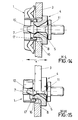
- part (1) is rotated over a right angle as regards part (4), as shown in figure 12, a semi-sectional view of which is shown in figure 15 along line M-N and a full sectional view in figure 13 along line I-J, the internal ring's (17) recesses (16) will also be at a right angle to the arms (8), which means that such arms , as is best seen in figure 15, face the inwall of the ring and cannot hence open to allow passage of the head (10).
- the device provides a fast coupling and uncoupling of elements (3) and (13), merely by pressure, when parts (1) and (4) take up the positions of figures 11 and 14, or an immovable coupling by accident or otherwise, when the said parts are rotated to the position of figures 12, 13 and 15.
Landscapes
- Engineering & Computer Science (AREA)
- General Engineering & Computer Science (AREA)
- Mechanical Engineering (AREA)
- Insertion Pins And Rivets (AREA)
- Clamps And Clips (AREA)
Applications Claiming Priority (2)
| Application Number | Priority Date | Filing Date | Title |
|---|---|---|---|
| ES9002510A ES2026023A6 (es) | 1990-10-03 | 1990-10-03 | Elemento de fijacion en mecanicas tipo racks normalizados. |
| ES9002510 | 1990-10-03 |
Publications (2)
| Publication Number | Publication Date |
|---|---|
| EP0479705A2 true EP0479705A2 (de) | 1992-04-08 |
| EP0479705A3 EP0479705A3 (en) | 1993-02-03 |
Family
ID=8269033
Family Applications (1)
| Application Number | Title | Priority Date | Filing Date |
|---|---|---|---|
| EP19910500070 Withdrawn EP0479705A3 (en) | 1990-10-03 | 1991-06-27 | Fixing element for normalised rack-like mechanics |
Country Status (2)
| Country | Link |
|---|---|
| EP (1) | EP0479705A3 (de) |
| ES (1) | ES2026023A6 (de) |
Cited By (2)
| Publication number | Priority date | Publication date | Assignee | Title |
|---|---|---|---|---|
| WO1998033231A1 (en) * | 1997-01-29 | 1998-07-30 | Chang Eung Soon | Antenna for radio transmitter and receiver |
| FR2906322A1 (fr) * | 2006-09-27 | 2008-03-28 | Cera | Dispositif de fixation elastique comprenant une bague deformable |
Citations (3)
| Publication number | Priority date | Publication date | Assignee | Title |
|---|---|---|---|---|
| GB274827A (en) * | 1926-07-23 | 1927-12-01 | Carr Fastener Co Ltd | Improvements in or relating to snap fasteners |
| DE2919023A1 (de) * | 1979-05-11 | 1980-11-20 | Itw Ateco Gmbh | Druckknopf aus kunststoff |
| EP0428798A1 (de) * | 1989-11-21 | 1991-05-29 | Click Connections Corporation | Verbinder |
-
1990
- 1990-10-03 ES ES9002510A patent/ES2026023A6/es not_active Expired - Lifetime
-
1991
- 1991-06-27 EP EP19910500070 patent/EP0479705A3/en not_active Withdrawn
Patent Citations (3)
| Publication number | Priority date | Publication date | Assignee | Title |
|---|---|---|---|---|
| GB274827A (en) * | 1926-07-23 | 1927-12-01 | Carr Fastener Co Ltd | Improvements in or relating to snap fasteners |
| DE2919023A1 (de) * | 1979-05-11 | 1980-11-20 | Itw Ateco Gmbh | Druckknopf aus kunststoff |
| EP0428798A1 (de) * | 1989-11-21 | 1991-05-29 | Click Connections Corporation | Verbinder |
Cited By (4)
| Publication number | Priority date | Publication date | Assignee | Title |
|---|---|---|---|---|
| WO1998033231A1 (en) * | 1997-01-29 | 1998-07-30 | Chang Eung Soon | Antenna for radio transmitter and receiver |
| AU723471B2 (en) * | 1997-01-29 | 2000-08-24 | Eung-Soon Chang | Antenna for radio transmitter and receiver |
| FR2906322A1 (fr) * | 2006-09-27 | 2008-03-28 | Cera | Dispositif de fixation elastique comprenant une bague deformable |
| EP1906032A1 (de) * | 2006-09-27 | 2008-04-02 | Centre d'Etude et de Recherche pour l'Automobile (CERA) | Einen deformierbaren Ring umfassende elastische Befestigungsvorrichtung |
Also Published As
| Publication number | Publication date |
|---|---|
| EP0479705A3 (en) | 1993-02-03 |
| ES2026023A6 (es) | 1992-04-01 |
Similar Documents
| Publication | Publication Date | Title |
|---|---|---|
| CA1241853A (en) | Device for holding a screw or the like | |
| US3741405A (en) | Load lock | |
| US6682282B2 (en) | Rack mount panel fastener with interchangeable thread size | |
| US5256019A (en) | Washerless self-captivating screw | |
| JPH0643844B2 (ja) | プラスチック製押込みナット | |
| US3892031A (en) | Method of capturing screw fastener | |
| EP1512900A1 (de) | Pneumatische Verriegelungsvorrichtung | |
| EP2985573B1 (de) | Befestigungsvorrichtung für ein Elektronikgerät und Verfahren zum Befestigen eines Elektronikgeräts | |
| EP0479705A2 (de) | Befestigungselement für genormte Gestellaufbauten | |
| DE102010025778B4 (de) | Vorrichtung zum Verbinden zweier Bauteile | |
| DE4403907A1 (de) | Personal-Computer mit einem Gehäuse, einer Hauptplatine, Steckkarten und einer Haltevorrichtung hierfür | |
| DE69609057T2 (de) | Eine Vorrichtung für die Befestigung einer Stange auf eine Abstützung, wie zum Beispiel eine Mauer | |
| US5074727A (en) | Threaded device retainer | |
| JPS63308209A (ja) | ナットー保持器組立体 | |
| US5119665A (en) | Installation tool for captive panel fastener | |
| US7241096B2 (en) | Captive screw with deployable knob | |
| EP0026865B1 (de) | Vorrichtung zur Entnahme eines Brandmelders aus einem Sockel | |
| DE29819672U1 (de) | Bereitstellungshalterung für Schrauben | |
| CN217943181U (zh) | 一种活动扳手 | |
| DE102004048436A1 (de) | Steckhülse zur Befestigung eines Bauteils in einer Bohrung | |
| JPH0583424U (ja) | プラスチック製の押し込みナット | |
| JP2532270Y2 (ja) | 配管固定具 | |
| DE102005037200A1 (de) | Rohrschelle | |
| CA1119025A (en) | Improvements brought to insert nuts and related mounting systems | |
| JPH05263811A (ja) | 筺体連結治具及びこれを用いた筺体連結機構 |
Legal Events
| Date | Code | Title | Description |
|---|---|---|---|
| PUAI | Public reference made under article 153(3) epc to a published international application that has entered the european phase |
Free format text: ORIGINAL CODE: 0009012 |
|
| AK | Designated contracting states |
Kind code of ref document: A2 Designated state(s): AT BE CH DE DK FR GB GR IT LI LU NL SE |
|
| PUAL | Search report despatched |
Free format text: ORIGINAL CODE: 0009013 |
|
| AK | Designated contracting states |
Kind code of ref document: A3 Designated state(s): AT BE CH DE DK FR GB GR IT LI LU NL SE |
|
| STAA | Information on the status of an ep patent application or granted ep patent |
Free format text: STATUS: THE APPLICATION HAS BEEN WITHDRAWN |
|
| 18W | Application withdrawn |
Withdrawal date: 19930208 |