EP0478762B2 - Verfahren und vorrichtung zum trennen einer fasersuspension - Google Patents
Verfahren und vorrichtung zum trennen einer fasersuspension Download PDFInfo
- Publication number
- EP0478762B2 EP0478762B2 EP91908761A EP91908761A EP0478762B2 EP 0478762 B2 EP0478762 B2 EP 0478762B2 EP 91908761 A EP91908761 A EP 91908761A EP 91908761 A EP91908761 A EP 91908761A EP 0478762 B2 EP0478762 B2 EP 0478762B2
- Authority
- EP
- European Patent Office
- Prior art keywords
- wall
- filter material
- fibre suspension
- filter
- coarse fraction
- Prior art date
- Legal status (The legal status is an assumption and is not a legal conclusion. Google has not performed a legal analysis and makes no representation as to the accuracy of the status listed.)
- Expired - Lifetime
Links
- 239000000835 fiber Substances 0.000 title claims abstract description 98
- 239000000725 suspension Substances 0.000 title claims abstract description 93
- 238000000034 method Methods 0.000 title claims description 7
- 239000000463 material Substances 0.000 claims abstract description 60
- 239000002245 particle Substances 0.000 claims abstract description 19
- 239000007788 liquid Substances 0.000 claims abstract description 14
- 238000006073 displacement reaction Methods 0.000 claims abstract description 6
- 239000007921 spray Substances 0.000 claims description 57
- 238000005507 spraying Methods 0.000 claims description 7
- 238000007599 discharging Methods 0.000 claims description 5
- 239000010893 paper waste Substances 0.000 description 7
- 229920001131 Pulp (paper) Polymers 0.000 description 6
- 238000000926 separation method Methods 0.000 description 6
- XLYOFNOQVPJJNP-UHFFFAOYSA-N water Substances O XLYOFNOQVPJJNP-UHFFFAOYSA-N 0.000 description 6
- 239000000706 filtrate Substances 0.000 description 3
- 230000002706 hydrostatic effect Effects 0.000 description 3
- 238000004140 cleaning Methods 0.000 description 2
- 230000004048 modification Effects 0.000 description 2
- 238000012986 modification Methods 0.000 description 2
- 230000008719 thickening Effects 0.000 description 2
- 238000007796 conventional method Methods 0.000 description 1
- 230000000694 effects Effects 0.000 description 1
- 238000005188 flotation Methods 0.000 description 1
- 239000002023 wood Substances 0.000 description 1
Images
Classifications
-
- D—TEXTILES; PAPER
- D21—PAPER-MAKING; PRODUCTION OF CELLULOSE
- D21D—TREATMENT OF THE MATERIALS BEFORE PASSING TO THE PAPER-MAKING MACHINE
- D21D1/00—Methods of beating or refining; Beaters of the Hollander type
- D21D1/20—Methods of refining
- D21D1/40—Washing the fibres
-
- D—TEXTILES; PAPER
- D21—PAPER-MAKING; PRODUCTION OF CELLULOSE
- D21D—TREATMENT OF THE MATERIALS BEFORE PASSING TO THE PAPER-MAKING MACHINE
- D21D5/00—Purification of the pulp suspension by mechanical means; Apparatus therefor
- D21D5/02—Straining or screening the pulp
- D21D5/06—Rotary screen-drums
-
- D—TEXTILES; PAPER
- D21—PAPER-MAKING; PRODUCTION OF CELLULOSE
- D21F—PAPER-MAKING MACHINES; METHODS OF PRODUCING PAPER THEREON
- D21F1/00—Wet end of machines for making continuous webs of paper
- D21F1/66—Pulp catching, de-watering, or recovering; Re-use of pulp-water
- D21F1/74—Pulp catching, de-watering, or recovering; Re-use of pulp-water using cylinders
Definitions
- the present invention relates to a method of separating a fibre suspension containing undesirable, relatively small particles by a filter device, the device comprising a hollow filter drum with a circumferential wall of filter material, and a container, in which the filter drum is situated with the drum axis horizontal.
- the invention also relates to a device for separating a fibre suspension.
- the fibre suspension to be separated is supplied to the container, such that the filter drum is at least partly immersed in the suspension.
- the hydrostatic pressure in the fibre suspension in the container forces a fine fraction of the fibre suspension through the part of the wall of filter material of the filter body which is immersed in the fibre suspension, so that fibres are deposited and form a layer of fibres on the filter material.
- the formed layer of fibres constitutes in itself a filter medium, which in effect has a finer mesh than the filter material of the filter body and which merely allows water from the fibre suspension in the container to pass through.
- GB 1 362 422 describes a method of and an apparatus for dewatering a pulp suspension having a filter drum partially submerged in the suspension.
- the pulp suspension is sprayed onto a portion of the drum above the level of the suspension to force a majority of the suspended matter through the wall of the drum and to clean the drum before the suspension is further dewatered under hydrostatic pressure.
- a filter device for thickening fibre suspensions is known from US 4138338, which discloses a disc filter with an inlet tank for a fibre suspension to be thickened. From the inlet tank fibre suspension flows directly into a container, in which the discs are immersed in fibre suspension. To increase the dewatering capacity of the disc filter a number of spray members is arranged to spray liquid, for instance a volume of the fibre suspension to be thickened, onto the disc walls of filter material which are immersed in the fibre suspension in the container, so that creation of tightly packed fibre layers on the walls is prevented.
- the known filter devices described above are not suited for the separation of undesired relatively small particles from fibre suspensions, since most of such small particles would be trapped by the layer of fibres on the filter material or by thickened fibre suspension during the separation. Consequently, in practice the known filter devices have only usually been used for thickening of fibre suspensions, i.e. mere dewatering of the latter. Conventionally, undesired relatively small particles are therefore initially separated from the fibre suspensions by other kinds of separation devices, for instance by flotation plants. Then, the fibre suspensions thus cleaned can be dewatered, for instance by the known filter devices of the kind described above.
- the object of the present Invention is to provide a new separation method, which reduces the costs for cleaning and dewatering fibre suspensions, preferably fibre suspensicns created from waste paper pulp.
- a further object of the present invention is to provide a new device for accomplishing the new separation method.
- a filter device having a hollow filter drum with a circumferential wall of filter material, and a container in which the filter drum is situated with the drum axis horizontal
- the method including spraying the entire fibre suspension to be separated in the form of at least one liquid jet onto said wall of filter material to force a fine fraction of the suspension containing most of said undesired particles through said wall of filter material into the hollow filter drum thereby leaving a pool of created coarse fraction of the fibre suspension mainly containing fibres in the container outside the filter drum said jet of fibre suspension being sprayed onto the part of the wall of filter material which is above said pool of coarse fraction, rotating the drum about its horizontal axis to provide relative displacement between the liquid jet and the filter material, and to displace the wall of filter material alternately up and down through the surface of said pool of coarse fraction, dewatering said coarse fraction of the fibre suspension through the wall of filter material, and discharging said dewatered coarse fraction from the
- the advantage gained is that in one and the same filter device the fibre suspension is separated from undesired particles and dewatered, which means significant savings in costs as compared to the conventional method utilising two separate devices for the separation of the undesired particles and the dewatering of the fibre suspension, respectively.
- the sprayed elongated fibres of relatively large specific surface are rapidly retarded by the frictional drag between these and the surrounding medium (air or liquid), whereas undesired relatively small particles of relatively small specific surface substantially maintain their velocity, and thereby penetrate said wall of filter material.
- Said rapid retardation of the fibres has the advantage that the fibres do not press into and clog the screen passages of the filter material.
- the invention also relates to a device for separating a fibre suspension containing undesired, relatively small particles, comprising a hollow filter drum with a circumferential wall of filter material, a container in which the filter drum is situated with the drum axis horizontal, means for supplying fibre suspension to be separated, spray means arranged to spray fibre suspension onto the wall of filter material, said supplying means being arranged to supply the fibre suspension to be separated solely by means of said spray means, said spray means being adapted to spray the fibre suspension onto the wall of the filter drum to force a fine fraction of the fibre suspension containing most of said undesired relatively small particles through said wall of filter material into the hollow filter drum and leave a pool of a coarse fraction of the fibre suspension mainly containing fibres in the container outside the filter body, said coarse fraction of the fibre suspension being dewatered through said wall of filter material during operation, means for rotating the filter drum about its horizontal axis to provide relative displacement between the spray means and the wall of filter material and to displace the wall of filter material alternately up and down through the
- the fibre suspension in a device according to the invention, can be sprayed under a low frictional drag through a medium of air, whereby a relatively larger share of the liquid content of the fibre suspension can be passed directly through the filter material as compared to spraying of the fibre suspension through said pool of coarse fraction.
- the spray means is arranged to spray fibre suspension onto the part of the wall of filter material which is in said pool of coarse fraction the created relatively tightly packed fibre layer is continuously removed from the filter material during operation by means of the liquid jet from the spray means, which has the advantage that the coarse fraction of fibre suspension in the container is more efficiently dewatered through the filter material, since the filter material at least partly will be devoid of tightly packed fibre layers during operation.
- said spray means is arranged to spray fibre suspension onto the part of the wall of filter material which moves downwards in said pool of coarse fraction during operation and which consequently has only been covered with a relatively thin layer of fibres.
- Said spray means is advantageously arranged to spray fibre suspension on a zone of said downwards moving part of the wall of filter material situated in the vicinity of the surface of said pool of coarse fraction. At said zone the created fibre layer is very thin and is readily dissolved by the sprayed fibre suspension.
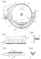
- the drum filter shown in figure 1 comprises a hollow filter body in the form of a horizontal drum 1 with a circular circumferential wall 2 of filter material.
- the drum 1 is rotatably journalled in a container 3.
- a drive motor 4 is engaged with the drum 1 via a gear wheel 5 for rotating the drum 1 around its centre axis. (The direction of rotation of the drum 1 is indicated by an arrow in figure 1).
- the fibre suspension to be separated is supplied to the drum filter by means of a spray member 6, which is above said pool of coarse fraction in the container 3 at the downwardly travelling side of the circumferential wall 2, and two spray members 7 and 8, which are situated in said pool of coarse fraction.
- the spray members 6-8 include supply pipes 9-11, respectively, for fibre suspension to be separated, which extend axially along the circumferential wall of the drum 1 (fig 2).
- Each supply pipe 9-11 is provided with a plurality of spray nozzles 12 (here eight), which are directed against the circumferential wall 2.
- each supply pipe 9-11 may be provided with only two spray nozzles 13, each spray nozzle 13 having an elongated outlet opening (fig 3 and 4).
- the spray member 7 is adapted to spray fibre suspension on a zone 14 at the downwardly travelling side of the circumferential wall 2 at a small distance from the surface of the coarse fraction.
- the removal device 15 is adapted to transfer removed fibre layers to a trough 16, which is provided with a conveyor screw 17.
- the interior of the drum 1 forms a filtrate chamber 18, which is connected to a device not shown for discharging the fine fraction from the drum filter.
- a spray member 19 for cleaning the filter material of the circumferential wall 2 by means of cleansing liquid, for instance water.
- the drum filter according to figure 1 is operated in the following way:
- All the fibre suspension to be separated for instance a fibre suspension produced from waste paper pulp and containing about 0.5 % fibres, undesired small particles substantially consisting of printing ink, and water, is sprayed in the form of liquid jets by means of the spray members 6-8 onto the circumferential wall 2 of filter material during rotation of the drum 1 by the drive motor 4, the fibre suspension being separated into a fine fraction of the fibre suspension, which passes through the circumferential wall 2 into the filtrate chamber 18 and which substantially contains undesired particles and water, and a coarse fraction of the fibre suspension, which is received in the container 3 and which substantially contains fibres and water.
- the drum filter according to figure 1 can be operated so that the obtained fibre pulp will have a consistency of about 8-12%. However, if a lower consistency of the fibre pulp of about 3-4% would be acceptable the removal device 15 can be replaced by an overflow in the container 3 for the coarse fraction of fibre suspension at the upwardly travelling side of the circumferential wall 2. In this case further spray members for fibre suspension to be separated may be arranged along the drum 2 above the pool of coarse fraction, which would increase the capacity of the drum filter.
- each spray nozzle 12 may advantageously be formed with an increasing cross-sectional area towards the opening (fig 5), whereby a clogging or plug of fibre pulp can more easily be forced through the nozzle when the operational pressure is restored after a pressure drop.
Landscapes
- Engineering & Computer Science (AREA)
- Mechanical Engineering (AREA)
- Filtering Materials (AREA)
- Paper (AREA)
- Separation Using Semi-Permeable Membranes (AREA)
- Preliminary Treatment Of Fibers (AREA)
- Separation Of Solids By Using Liquids Or Pneumatic Power (AREA)
- Spinning Methods And Devices For Manufacturing Artificial Fibers (AREA)
- Medicines Containing Material From Animals Or Micro-Organisms (AREA)
- Preparation Of Compounds By Using Micro-Organisms (AREA)
Claims (5)
- Verfahren zur Auftrennung einer Fasersuspension mit unerwünschten, relativ kleinen Partikeln durch eine Filtervorrichtung, die eine hohle Filtertrommel (1) mit einer Umfangswand (2) aus Filtermaterial und einen Behälter (3) aufweist, in dem die Filtertrommel (1) mit einer horizontalen Achse versehen ist, umfassend- Aufsprühen der ganzen aufzutrennenden Fasersuspension in Form zumindest eines Flüssigkeitsstrahls auf die Wand (2) aus Filtermaterial, um eine feine, die meisten der unerwünschten Partikel enthaltende Fraktion der Suspension durch die Wand aus Filtermaterial in die hohle Filtertrommel (1) zu drücken, wodurch eine Ansammlung der entstandenen Grobfraktion der hauptsächlich Fasern enthaltenden Fasersuspension in dem Behälter (3) außerhalb des Filterkörpers zurückgelassen wird,
wobei der Fasersuspensionsstrahl auf denjenigen Teil der Wand (2) aus Filtermaterial gesprüht wird, der oberhalb der Ansammlung aus Grobfraktion gelegen ist, während die Trommel um ihre horizontale Achse gedreht wird, um eine relative Verschiebung zwischen dem Flüssigkeitsstrahl und dem Filtermaterial vorzusehen; und um die Wand aus Filtermaterial durch die Oberfläche der Ansammlung aus Grobfraktion abwechselnd auf und ab zu verschieben;- Entwässern der Grobfraktion der Fasersuspension durch die Wand aus Filtermaterial und- Entfernen der entwässerten Grobfraktion aus dem Behälter,dadurch gekennzeichnet, daß- zumindest ein weiterer Flüssigkeitsstrahl aus Suspension auf denjenigen Teil der Wand aus Filtermaterial gesprüht wird, der sich in der Ansammlung von Grobfraktion befindet. - Vorrichtung zur Auftrennung einer unerwünschte, relativ kleine Partikel enthaltenden Fasersuspension- mit einer hohlen Filtertrommel (1) mit einer Umfangswand (2) aus Filtermaterial,- mit einem Behälter (3), in dem die Filtertrommel mit einer horizontalen Achse versehen ist,- mit Mitteln zur Zufuhr von aufzutrennender Fasersuspension,- mit Sprühmitteln (6, 7, 8) zum Sprühen von Fasersuspension auf die Wand aus Filtermaterial,wobei die Zufuhrmittel aufzutrennende Fasersuspension nur mittels Sprühmitteln (6 bis 8) zuführen, wobei die Sprühmittel die Fasersuspension auf die Wand (2) der Filtertrommel sprühen, um eine feine, die meisten der unerwünschten, relativ kleine Partikel enthaltende Fraktion aus Fasersuspension durch die Wand aus Filtermaterial in die hohle Filtertrommel zu drücken und eine Ansammlung einer groben, hauptsächlich Fasern enthaltenden Fraktion der Fasersuspension in dem Behälter (3) außerhalb des Filterkörpers zurückzulassen, wobei im Betrieb die grobe Fraktion der Fasersuspension durch die Wand aus Filtermaterial entwässert wird,- mit einem Mittel zum Rotieren der Filtertrommel um ihre horizontale Achse, um eine relative Verschiebung zwischen den Sprühmitteln und der Wand aus Filtermaterial vorzusehen und um die Wand (2) aus Filtermaterial durch die Oberfläche der Ansammlung von Grobfraktion abwechselnd auf und ab zu verschieben, wobei die Sprühmittel (6 bis 8) Fasersuspension auf denjenigen Teil der Wand (2) aus Filtermaterial sprühen, der sich oberhalb der Ansammlung von Grobfraktion befindet, und- mit Mitteln (15, 16, 17) zum Entfernen der entwässerten Grobfraktion aus dem Behälter,dadurch gekennzeichnet, daß- die Sprühmittel (6, 7, 8) Fasersuspension auf denjenigen Teil der Wand aus Filtermaterial sprühen, der in der Ansammlung von Grobfraktion gelegen ist.
- Vorrichtung nach Anspruch 2, dadurch gekennzeichnet, daß die Sprühmittel (6, 7, 8) Fasersuspension auf den Teil der Wand (2) aus Filtermaterial sprühen, der sich im Betrieb nach unten zu der Ansammlung von Grobfraktion bewegt.
- Vorrichtung nach Anspruch 3, dadurch gekennzeichnet, daß die Sprühmittel (6, 7, 8) Fasersuspension auf einen Bereich (14) an dem sich nach unten bewegenden Teil der Wand (2) aus Filtermaterial sprühen, der in der Nähe der Oberfläche der Ansammlung von Grobfraktion gelegen ist.
- Vorrichtung nach Anspruch 2, 3 oder 4, dadurch gekennzeichnet, daß die Sprühmittel (6, 7, 8) eine Zufuhrleitung (9, 10, 11) für Fasersuspension, die sich axial entlang der Umfangswand (2) der Trommel (1) erstreckt, und zumindest eine Sprühdüse (12) umfassen, die mit der Zufuhrleitung zum Sprühen der Fasersuspension auf die Umfangswand aus Filtermaterial verbunden ist.
Applications Claiming Priority (3)
| Application Number | Priority Date | Filing Date | Title |
|---|---|---|---|
| SE9001322A SE465967B (sv) | 1990-04-11 | 1990-04-11 | Foerfarande och anordning foer separering av en fibersuspension |
| SE9001322 | 1990-04-11 | ||
| PCT/SE1991/000208 WO1991015629A1 (en) | 1990-04-11 | 1991-03-19 | Method and device for separating a fibre suspension |
Publications (3)
| Publication Number | Publication Date |
|---|---|
| EP0478762A1 EP0478762A1 (de) | 1992-04-08 |
| EP0478762B1 EP0478762B1 (de) | 1994-08-24 |
| EP0478762B2 true EP0478762B2 (de) | 1997-10-29 |
Family
ID=20379157
Family Applications (1)
| Application Number | Title | Priority Date | Filing Date |
|---|---|---|---|
| EP91908761A Expired - Lifetime EP0478762B2 (de) | 1990-04-11 | 1991-03-19 | Verfahren und vorrichtung zum trennen einer fasersuspension |
Country Status (9)
| Country | Link |
|---|---|
| US (1) | US5296098A (de) |
| EP (1) | EP0478762B2 (de) |
| JP (1) | JP2801778B2 (de) |
| AT (1) | ATE110427T1 (de) |
| CA (1) | CA2060503C (de) |
| DE (1) | DE69103602T3 (de) |
| FI (1) | FI104433B (de) |
| SE (1) | SE465967B (de) |
| WO (1) | WO1991015629A1 (de) |
Families Citing this family (9)
| Publication number | Priority date | Publication date | Assignee | Title |
|---|---|---|---|---|
| US5266168A (en) * | 1991-12-20 | 1993-11-30 | The Black Clawson Company | Gravity type pulp washer or thickener with rotating disrupters |
| FI96328C (fi) * | 1994-02-04 | 1996-06-10 | Ahlstroem Oy | Menetelmä ja laite uusiomassan käsittelemiseksi |
| CA2247032A1 (en) * | 1996-02-28 | 1997-09-04 | Ryan M. Smith | Improved recovery of fine fibers from suspensions containing fibers and contaminants |
| GB0413068D0 (en) * | 2004-06-11 | 2004-07-14 | Imerys Minerals Ltd | Treatment of pulp |
| DK1961475T3 (da) * | 2007-02-21 | 2020-08-31 | Veolia Water Solutions & Tech | Højtryksrensningsanordning |
| DE102010038417A1 (de) * | 2010-07-26 | 2012-01-26 | Huber Se | Vorrichtung und Verfahren zum Entfernen von Siebgut aus einer Flüssigkeit |
| FI3833464T3 (fi) * | 2018-08-10 | 2025-11-10 | Kadant Black Clawson Llc | Levysuodattimet ja levysuodattimien käyttömenetelmät |
| JP7033248B2 (ja) * | 2018-11-05 | 2022-03-10 | 株式会社石垣 | フィルタープレスのろ布洗浄方法 |
| CN118142842B (zh) * | 2024-02-21 | 2026-02-06 | 中国建筑第五工程局有限公司 | 一种淹没式粘性物料颗粒与泥浆快速分选设备 |
Family Cites Families (16)
| Publication number | Priority date | Publication date | Assignee | Title |
|---|---|---|---|---|
| SE187797C1 (de) * | 1963-01-01 | |||
| US3002621A (en) * | 1957-01-28 | 1961-10-03 | Wilfred F Mathewson | Pulp screen |
| US3521751A (en) * | 1967-12-15 | 1970-07-28 | Theodorus H Holthuis | Filtering method and apparatus |
| GB1265803A (de) * | 1968-05-07 | 1972-03-08 | ||
| SE339165B (de) * | 1969-04-22 | 1971-09-27 | Calor & Sjoegren Ab | |
| US3591009A (en) * | 1969-08-22 | 1971-07-06 | Oscar Luthi | Disc filter having filtrate directing means |
| US3713540A (en) * | 1971-04-15 | 1973-01-30 | Fmc Corp | Apparatus for treating waste materials |
| US3789978A (en) * | 1971-04-20 | 1974-02-05 | B Janson | Method and apparatus for separating finer particles from coarse particles suspended in a liquid |
| SE367849B (de) * | 1972-10-25 | 1974-06-10 | Celleco Ab | |
| DE2626458C2 (de) * | 1976-06-12 | 1978-08-17 | J.M. Voith Gmbh, 7920 Heidenheim | Verfahren und Vorrichtung zur Erhöhung der Durchsatzleistung an Scheibenfiltern |
| US4056226A (en) * | 1976-07-29 | 1977-11-01 | Chromalloy American Corporation | Liquid manure spreader |
| SE402942B (sv) * | 1976-11-30 | 1978-07-24 | Ljungstrom Eva Kristina | Fraktioneringsapparat |
| CH632646A5 (de) * | 1978-09-22 | 1982-10-29 | Intradym Masch Ag | Verfahren und vorrichtung zum spritzen von beton. |
| FI71961C (fi) * | 1985-10-31 | 1987-03-09 | Enso Gutzeit Oy | Anordning foer tvaettning av cellulosa. |
| FI81136C (fi) * | 1987-11-11 | 1990-09-10 | Ahlstroem Oy | Foerfarande och anordning foer behandling av massa. |
| SE462597B (sv) * | 1988-11-25 | 1990-07-23 | Celleco Ab | Foerfarande och anordning foer fraktionering av suspensioner |
-
1990
- 1990-04-11 SE SE9001322A patent/SE465967B/sv not_active IP Right Cessation
-
1991
- 1991-03-19 AT AT91908761T patent/ATE110427T1/de not_active IP Right Cessation
- 1991-03-19 JP JP3508281A patent/JP2801778B2/ja not_active Expired - Lifetime
- 1991-03-19 CA CA002060503A patent/CA2060503C/en not_active Expired - Fee Related
- 1991-03-19 EP EP91908761A patent/EP0478762B2/de not_active Expired - Lifetime
- 1991-03-19 US US07/778,082 patent/US5296098A/en not_active Expired - Fee Related
- 1991-03-19 DE DE69103602T patent/DE69103602T3/de not_active Expired - Fee Related
- 1991-03-19 WO PCT/SE1991/000208 patent/WO1991015629A1/en not_active Ceased
- 1991-12-10 FI FI915802A patent/FI104433B/fi active
Also Published As
| Publication number | Publication date |
|---|---|
| DE69103602D1 (de) | 1994-09-29 |
| US5296098A (en) | 1994-03-22 |
| JP2801778B2 (ja) | 1998-09-21 |
| ATE110427T1 (de) | 1994-09-15 |
| SE465967B (sv) | 1991-11-25 |
| SE9001322L (sv) | 1991-10-12 |
| DE69103602T3 (de) | 1998-02-19 |
| EP0478762A1 (de) | 1992-04-08 |
| DE69103602T2 (de) | 1994-12-22 |
| WO1991015629A1 (en) | 1991-10-17 |
| EP0478762B1 (de) | 1994-08-24 |
| FI104433B (fi) | 2000-01-31 |
| CA2060503C (en) | 1996-11-26 |
| SE9001322D0 (sv) | 1990-04-11 |
| JPH04506843A (ja) | 1992-11-26 |
| CA2060503A1 (en) | 1991-10-12 |
| FI915802A0 (fi) | 1991-12-10 |
Similar Documents
| Publication | Publication Date | Title |
|---|---|---|
| EP0642375B1 (de) | Vorrichtung zur trennung fester teilchen von einer flüssigkeit | |
| EP0515492B1 (de) | Gerät zum filtrieren von suspensionen und betriebsverfahren des gerätes | |
| FI90500C (fi) | Ennaltamäärättyä suurikokoisemman hienojakoisen aineen poistoon tarkoitettu vedenselkeytyslaitteisto | |
| US6833077B2 (en) | Sequential swinging precoat removal and renewal system, filter so equipped and method | |
| EP0478762B2 (de) | Verfahren und vorrichtung zum trennen einer fasersuspension | |
| WO1991012870A1 (en) | A method and apparatus for filtering a particle-liquid suspension | |
| US2765915A (en) | Method of and means for recovering fibers from pulp-water | |
| WO1990012919A1 (en) | Dewatering device | |
| US5296152A (en) | Apparatus for filtering suspensions and a method of operating the apparatus | |
| KR200183914Y1 (ko) | 공기총에 의한 여과조 세척장치 | |
| EP1401555B1 (de) | Filter mit sequentiellem schwenkbarem system zur entfernung und zur erneuerung einer filterhilfschicht | |
| KR0182391B1 (ko) | 현탁액 분별 장치 | |
| KR200384527Y1 (ko) | 제지공정의 폐수 정선장치 | |
| US20070102373A1 (en) | Apparatus for separating suspensions | |
| KR19990087326A (ko) | 섬유 현탄액으로부터의 섬유의 정제 및 생산을 제어하는 방법 및 장치 | |
| RU2091177C1 (ru) | Устройство для очистки сточных вод и других жидкостей | |
| KR100725466B1 (ko) | 제지공정의 폐수 정선장치 | |
| RU2069103C1 (ru) | Устройство для очистки сточных вод и других жидкостей | |
| SU1510872A1 (ru) | Устройство дл очистки раствора декстрина | |
| RU2124383C1 (ru) | Фильтр | |
| JPS589609Y2 (ja) | 充填層濾過器 | |
| KR19990087327A (ko) | 섬유 및 오물을 함유하는 현탁액에서 미세 섬유를 회수하는 방법 및 장치 | |
| Vitec et al. | Foam drainage sleeve | |
| JPS6343160B2 (de) |
Legal Events
| Date | Code | Title | Description |
|---|---|---|---|
| PUAI | Public reference made under article 153(3) epc to a published international application that has entered the european phase |
Free format text: ORIGINAL CODE: 0009012 |
|
| 17P | Request for examination filed |
Effective date: 19911128 |
|
| AK | Designated contracting states |
Kind code of ref document: A1 Designated state(s): AT DE FR GB IT SE |
|
| 17Q | First examination report despatched |
Effective date: 19931015 |
|
| GRAA | (expected) grant |
Free format text: ORIGINAL CODE: 0009210 |
|
| ITF | It: translation for a ep patent filed | ||
| AK | Designated contracting states |
Kind code of ref document: B1 Designated state(s): AT DE FR GB IT SE |
|
| REF | Corresponds to: |
Ref document number: 110427 Country of ref document: AT Date of ref document: 19940915 Kind code of ref document: T |
|
| REF | Corresponds to: |
Ref document number: 69103602 Country of ref document: DE Date of ref document: 19940929 |
|
| PG25 | Lapsed in a contracting state [announced via postgrant information from national office to epo] |
Ref country code: SE Effective date: 19941124 |
|
| ET | Fr: translation filed | ||
| PLBI | Opposition filed |
Free format text: ORIGINAL CODE: 0009260 |
|
| 26 | Opposition filed |
Opponent name: VOITH SULZER STOFFAUFBEREITUNG GMBH Effective date: 19950524 |
|
| PLBF | Reply of patent proprietor to notice(s) of opposition |
Free format text: ORIGINAL CODE: EPIDOS OBSO |
|
| PLAW | Interlocutory decision in opposition |
Free format text: ORIGINAL CODE: EPIDOS IDOP |
|
| PLAW | Interlocutory decision in opposition |
Free format text: ORIGINAL CODE: EPIDOS IDOP |
|
| PUAH | Patent maintained in amended form |
Free format text: ORIGINAL CODE: 0009272 |
|
| STAA | Information on the status of an ep patent application or granted ep patent |
Free format text: STATUS: PATENT MAINTAINED AS AMENDED |
|
| ITF | It: translation for a ep patent filed | ||
| 27A | Patent maintained in amended form |
Effective date: 19971029 |
|
| AK | Designated contracting states |
Kind code of ref document: B2 Designated state(s): AT DE FR GB IT SE |
|
| ET3 | Fr: translation filed ** decision concerning opposition | ||
| PGFP | Annual fee paid to national office [announced via postgrant information from national office to epo] |
Ref country code: AT Payment date: 19990311 Year of fee payment: 9 |
|
| PG25 | Lapsed in a contracting state [announced via postgrant information from national office to epo] |
Ref country code: AT Free format text: LAPSE BECAUSE OF NON-PAYMENT OF DUE FEES Effective date: 20000319 |
|
| REG | Reference to a national code |
Ref country code: GB Ref legal event code: IF02 |
|
| PGFP | Annual fee paid to national office [announced via postgrant information from national office to epo] |
Ref country code: FR Payment date: 20020312 Year of fee payment: 12 |
|
| PGFP | Annual fee paid to national office [announced via postgrant information from national office to epo] |
Ref country code: GB Payment date: 20020320 Year of fee payment: 12 |
|
| PGFP | Annual fee paid to national office [announced via postgrant information from national office to epo] |
Ref country code: DE Payment date: 20020327 Year of fee payment: 12 |
|
| PG25 | Lapsed in a contracting state [announced via postgrant information from national office to epo] |
Ref country code: GB Free format text: LAPSE BECAUSE OF NON-PAYMENT OF DUE FEES Effective date: 20030319 |
|
| PG25 | Lapsed in a contracting state [announced via postgrant information from national office to epo] |
Ref country code: DE Free format text: LAPSE BECAUSE OF NON-PAYMENT OF DUE FEES Effective date: 20031001 |
|
| GBPC | Gb: european patent ceased through non-payment of renewal fee |
Effective date: 20030319 |
|
| PG25 | Lapsed in a contracting state [announced via postgrant information from national office to epo] |
Ref country code: FR Free format text: LAPSE BECAUSE OF NON-PAYMENT OF DUE FEES Effective date: 20031127 |
|
| REG | Reference to a national code |
Ref country code: FR Ref legal event code: ST |
|
| PG25 | Lapsed in a contracting state [announced via postgrant information from national office to epo] |
Ref country code: IT Free format text: LAPSE BECAUSE OF NON-PAYMENT OF DUE FEES Effective date: 20050319 |