EP0478635B1 - Beihilfepumpe für das herz - Google Patents
Beihilfepumpe für das herz Download PDFInfo
- Publication number
- EP0478635B1 EP0478635B1 EP90909556A EP90909556A EP0478635B1 EP 0478635 B1 EP0478635 B1 EP 0478635B1 EP 90909556 A EP90909556 A EP 90909556A EP 90909556 A EP90909556 A EP 90909556A EP 0478635 B1 EP0478635 B1 EP 0478635B1
- Authority
- EP
- European Patent Office
- Prior art keywords
- chamber
- rotor
- impeller
- shaft
- lubricant
- Prior art date
- Legal status (The legal status is an assumption and is not a legal conclusion. Google has not performed a legal analysis and makes no representation as to the accuracy of the status listed.)
- Expired - Lifetime
Links
- 230000000747 cardiac effect Effects 0.000 title 1
- 239000012530 fluid Substances 0.000 claims abstract description 40
- 239000000314 lubricant Substances 0.000 claims description 52
- 210000001124 body fluid Anatomy 0.000 claims description 19
- 230000010412 perfusion Effects 0.000 claims description 19
- 238000007789 sealing Methods 0.000 claims description 16
- 238000001802 infusion Methods 0.000 claims description 14
- 238000004891 communication Methods 0.000 claims description 6
- 230000001154 acute effect Effects 0.000 claims description 3
- 230000008878 coupling Effects 0.000 claims description 2
- 238000010168 coupling process Methods 0.000 claims description 2
- 238000005859 coupling reaction Methods 0.000 claims description 2
- 238000009434 installation Methods 0.000 claims 1
- FAPWRFPIFSIZLT-UHFFFAOYSA-M Sodium chloride Chemical compound [Na+].[Cl-] FAPWRFPIFSIZLT-UHFFFAOYSA-M 0.000 abstract description 39
- 210000004369 blood Anatomy 0.000 abstract description 30
- 239000008280 blood Substances 0.000 abstract description 30
- 210000005240 left ventricle Anatomy 0.000 abstract description 8
- 239000011780 sodium chloride Substances 0.000 description 15
- 229940079593 drug Drugs 0.000 description 3
- 239000003814 drug Substances 0.000 description 3
- 229920002492 poly(sulfone) Polymers 0.000 description 3
- 239000004417 polycarbonate Substances 0.000 description 3
- 229920000515 polycarbonate Polymers 0.000 description 3
- 239000010409 thin film Substances 0.000 description 3
- OKTJSMMVPCPJKN-UHFFFAOYSA-N Carbon Chemical compound [C] OKTJSMMVPCPJKN-UHFFFAOYSA-N 0.000 description 2
- 239000000853 adhesive Substances 0.000 description 2
- 230000001070 adhesive effect Effects 0.000 description 2
- 210000000702 aorta abdominal Anatomy 0.000 description 2
- 229910002804 graphite Inorganic materials 0.000 description 2
- 239000010439 graphite Substances 0.000 description 2
- 238000004519 manufacturing process Methods 0.000 description 2
- 229910001220 stainless steel Inorganic materials 0.000 description 2
- 239000010935 stainless steel Substances 0.000 description 2
- 238000001356 surgical procedure Methods 0.000 description 2
- 238000003466 welding Methods 0.000 description 2
- 238000004804 winding Methods 0.000 description 2
- RYGMFSIKBFXOCR-UHFFFAOYSA-N Copper Chemical compound [Cu] RYGMFSIKBFXOCR-UHFFFAOYSA-N 0.000 description 1
- 229920004934 Dacron® Polymers 0.000 description 1
- 239000004593 Epoxy Substances 0.000 description 1
- HTTJABKRGRZYRN-UHFFFAOYSA-N Heparin Chemical compound OC1C(NC(=O)C)C(O)OC(COS(O)(=O)=O)C1OC1C(OS(O)(=O)=O)C(O)C(OC2C(C(OS(O)(=O)=O)C(OC3C(C(O)C(O)C(O3)C(O)=O)OS(O)(=O)=O)C(CO)O2)NS(O)(=O)=O)C(C(O)=O)O1 HTTJABKRGRZYRN-UHFFFAOYSA-N 0.000 description 1
- XEEYBQQBJWHFJM-UHFFFAOYSA-N Iron Chemical group [Fe] XEEYBQQBJWHFJM-UHFFFAOYSA-N 0.000 description 1
- 208000007536 Thrombosis Diseases 0.000 description 1
- RTAQQCXQSZGOHL-UHFFFAOYSA-N Titanium Chemical compound [Ti] RTAQQCXQSZGOHL-UHFFFAOYSA-N 0.000 description 1
- PXAWCNYZAWMWIC-UHFFFAOYSA-N [Fe].[Nd] Chemical compound [Fe].[Nd] PXAWCNYZAWMWIC-UHFFFAOYSA-N 0.000 description 1
- 230000002965 anti-thrombogenic effect Effects 0.000 description 1
- 239000003146 anticoagulant agent Substances 0.000 description 1
- 229940127219 anticoagulant drug Drugs 0.000 description 1
- 210000000709 aorta Anatomy 0.000 description 1
- 239000000560 biocompatible material Substances 0.000 description 1
- 230000015572 biosynthetic process Effects 0.000 description 1
- 238000010276 construction Methods 0.000 description 1
- 238000011109 contamination Methods 0.000 description 1
- 239000002826 coolant Substances 0.000 description 1
- 238000005260 corrosion Methods 0.000 description 1
- 230000007797 corrosion Effects 0.000 description 1
- 230000003247 decreasing effect Effects 0.000 description 1
- 230000001419 dependent effect Effects 0.000 description 1
- 238000007865 diluting Methods 0.000 description 1
- 229920001971 elastomer Polymers 0.000 description 1
- 239000000806 elastomer Substances 0.000 description 1
- 210000003743 erythrocyte Anatomy 0.000 description 1
- 239000010408 film Substances 0.000 description 1
- 210000001308 heart ventricle Anatomy 0.000 description 1
- 229960002897 heparin Drugs 0.000 description 1
- 229920000669 heparin Polymers 0.000 description 1
- 238000002513 implantation Methods 0.000 description 1
- 230000000977 initiatory effect Effects 0.000 description 1
- 230000007774 longterm Effects 0.000 description 1
- 229910052751 metal Inorganic materials 0.000 description 1
- 239000002184 metal Substances 0.000 description 1
- 238000000034 method Methods 0.000 description 1
- 238000012544 monitoring process Methods 0.000 description 1
- 230000001453 nonthrombogenic effect Effects 0.000 description 1
- 238000013021 overheating Methods 0.000 description 1
- 239000004033 plastic Substances 0.000 description 1
- 229920003023 plastic Polymers 0.000 description 1
- 229920001084 poly(chloroprene) Polymers 0.000 description 1
- 239000005020 polyethylene terephthalate Substances 0.000 description 1
- 229920002635 polyurethane Polymers 0.000 description 1
- 239000004814 polyurethane Substances 0.000 description 1
- 238000005086 pumping Methods 0.000 description 1
- 210000002254 renal artery Anatomy 0.000 description 1
- 239000013589 supplement Substances 0.000 description 1
- 210000000115 thoracic cavity Anatomy 0.000 description 1
- 239000010936 titanium Substances 0.000 description 1
- 229910052719 titanium Inorganic materials 0.000 description 1
Images

Classifications
-
- F—MECHANICAL ENGINEERING; LIGHTING; HEATING; WEAPONS; BLASTING
- F04—POSITIVE - DISPLACEMENT MACHINES FOR LIQUIDS; PUMPS FOR LIQUIDS OR ELASTIC FLUIDS
- F04D—NON-POSITIVE-DISPLACEMENT PUMPS
- F04D13/00—Pumping installations or systems
- F04D13/02—Units comprising pumps and their driving means
- F04D13/06—Units comprising pumps and their driving means the pump being electrically driven
-
- F—MECHANICAL ENGINEERING; LIGHTING; HEATING; WEAPONS; BLASTING
- F04—POSITIVE - DISPLACEMENT MACHINES FOR LIQUIDS; PUMPS FOR LIQUIDS OR ELASTIC FLUIDS
- F04D—NON-POSITIVE-DISPLACEMENT PUMPS
- F04D29/00—Details, component parts, or accessories
- F04D29/08—Sealings
- F04D29/10—Shaft sealings
- F04D29/106—Shaft sealings especially adapted for liquid pumps
- F04D29/108—Shaft sealings especially adapted for liquid pumps the sealing fluid being other than the working liquid or being the working liquid treated
-
- A—HUMAN NECESSITIES
- A61—MEDICAL OR VETERINARY SCIENCE; HYGIENE
- A61M—DEVICES FOR INTRODUCING MEDIA INTO, OR ONTO, THE BODY; DEVICES FOR TRANSDUCING BODY MEDIA OR FOR TAKING MEDIA FROM THE BODY; DEVICES FOR PRODUCING OR ENDING SLEEP OR STUPOR
- A61M60/00—Blood pumps; Devices for mechanical circulatory actuation; Balloon pumps for circulatory assistance
- A61M60/10—Location thereof with respect to the patient's body
- A61M60/122—Implantable pumps or pumping devices, i.e. the blood being pumped inside the patient's body
- A61M60/165—Implantable pumps or pumping devices, i.e. the blood being pumped inside the patient's body implantable in, on, or around the heart
- A61M60/178—Implantable pumps or pumping devices, i.e. the blood being pumped inside the patient's body implantable in, on, or around the heart drawing blood from a ventricle and returning the blood to the arterial system via a cannula external to the ventricle, e.g. left or right ventricular assist devices
-
- A—HUMAN NECESSITIES
- A61—MEDICAL OR VETERINARY SCIENCE; HYGIENE
- A61M—DEVICES FOR INTRODUCING MEDIA INTO, OR ONTO, THE BODY; DEVICES FOR TRANSDUCING BODY MEDIA OR FOR TAKING MEDIA FROM THE BODY; DEVICES FOR PRODUCING OR ENDING SLEEP OR STUPOR
- A61M60/00—Blood pumps; Devices for mechanical circulatory actuation; Balloon pumps for circulatory assistance
- A61M60/20—Type thereof
- A61M60/205—Non-positive displacement blood pumps
- A61M60/216—Non-positive displacement blood pumps including a rotating member acting on the blood, e.g. impeller
- A61M60/226—Non-positive displacement blood pumps including a rotating member acting on the blood, e.g. impeller the blood flow through the rotating member having mainly radial components
- A61M60/232—Centrifugal pumps
-
- A—HUMAN NECESSITIES
- A61—MEDICAL OR VETERINARY SCIENCE; HYGIENE
- A61M—DEVICES FOR INTRODUCING MEDIA INTO, OR ONTO, THE BODY; DEVICES FOR TRANSDUCING BODY MEDIA OR FOR TAKING MEDIA FROM THE BODY; DEVICES FOR PRODUCING OR ENDING SLEEP OR STUPOR
- A61M60/00—Blood pumps; Devices for mechanical circulatory actuation; Balloon pumps for circulatory assistance
- A61M60/40—Details relating to driving
- A61M60/403—Details relating to driving for non-positive displacement blood pumps
- A61M60/422—Details relating to driving for non-positive displacement blood pumps the force acting on the blood contacting member being electromagnetic, e.g. using canned motor pumps
-
- A—HUMAN NECESSITIES
- A61—MEDICAL OR VETERINARY SCIENCE; HYGIENE
- A61M—DEVICES FOR INTRODUCING MEDIA INTO, OR ONTO, THE BODY; DEVICES FOR TRANSDUCING BODY MEDIA OR FOR TAKING MEDIA FROM THE BODY; DEVICES FOR PRODUCING OR ENDING SLEEP OR STUPOR
- A61M60/00—Blood pumps; Devices for mechanical circulatory actuation; Balloon pumps for circulatory assistance
- A61M60/80—Constructional details other than related to driving
- A61M60/802—Constructional details other than related to driving of non-positive displacement blood pumps
- A61M60/818—Bearings
- A61M60/824—Hydrodynamic or fluid film bearings
-
- A—HUMAN NECESSITIES
- A61—MEDICAL OR VETERINARY SCIENCE; HYGIENE
- A61M—DEVICES FOR INTRODUCING MEDIA INTO, OR ONTO, THE BODY; DEVICES FOR TRANSDUCING BODY MEDIA OR FOR TAKING MEDIA FROM THE BODY; DEVICES FOR PRODUCING OR ENDING SLEEP OR STUPOR
- A61M60/00—Blood pumps; Devices for mechanical circulatory actuation; Balloon pumps for circulatory assistance
- A61M60/80—Constructional details other than related to driving
- A61M60/802—Constructional details other than related to driving of non-positive displacement blood pumps
- A61M60/827—Sealings between moving parts
- A61M60/829—Sealings between moving parts having a purge fluid supply
-
- F—MECHANICAL ENGINEERING; LIGHTING; HEATING; WEAPONS; BLASTING
- F04—POSITIVE - DISPLACEMENT MACHINES FOR LIQUIDS; PUMPS FOR LIQUIDS OR ELASTIC FLUIDS
- F04D—NON-POSITIVE-DISPLACEMENT PUMPS
- F04D29/00—Details, component parts, or accessories
- F04D29/06—Lubrication
- F04D29/061—Lubrication especially adapted for liquid pumps
-
- F—MECHANICAL ENGINEERING; LIGHTING; HEATING; WEAPONS; BLASTING
- F16—ENGINEERING ELEMENTS AND UNITS; GENERAL MEASURES FOR PRODUCING AND MAINTAINING EFFECTIVE FUNCTIONING OF MACHINES OR INSTALLATIONS; THERMAL INSULATION IN GENERAL
- F16J—PISTONS; CYLINDERS; SEALINGS
- F16J15/00—Sealings
- F16J15/16—Sealings between relatively-moving surfaces
- F16J15/162—Special parts or details relating to lubrication or cooling of the sealing itself
-
- A—HUMAN NECESSITIES
- A61—MEDICAL OR VETERINARY SCIENCE; HYGIENE
- A61M—DEVICES FOR INTRODUCING MEDIA INTO, OR ONTO, THE BODY; DEVICES FOR TRANSDUCING BODY MEDIA OR FOR TAKING MEDIA FROM THE BODY; DEVICES FOR PRODUCING OR ENDING SLEEP OR STUPOR
- A61M60/00—Blood pumps; Devices for mechanical circulatory actuation; Balloon pumps for circulatory assistance
- A61M60/10—Location thereof with respect to the patient's body
- A61M60/122—Implantable pumps or pumping devices, i.e. the blood being pumped inside the patient's body
- A61M60/126—Implantable pumps or pumping devices, i.e. the blood being pumped inside the patient's body implantable via, into, inside, in line, branching on, or around a blood vessel
- A61M60/148—Implantable pumps or pumping devices, i.e. the blood being pumped inside the patient's body implantable via, into, inside, in line, branching on, or around a blood vessel in line with a blood vessel using resection or like techniques, e.g. permanent endovascular heart assist devices
Definitions
- This invention relates to devices for conveying bodily fluids, and more particularly to body implantable left ventricle or whole heart assist pumps for bypassing the heart during open heart surgery, or to assist a disfunctional heart or left ventricle.
- Centrifugal blood pumps have long been recognized for their utility as a supplement to or replacement for the human heart, for example in assisting a damaged left ventricle, for temporary heart bypass in the event that such is required in open heart surgery, and for total heart bypass when two such pumps are implanted.
- Such pumps operate continuously and at high speeds, for example in the range of 4,000 to 7,000 rpm, and are relatively small, which facilitates implantation.
- centrifugal blood pumps A major problem with centrifugal blood pumps, however, is the need for a positive seal between the pump housing and the internal rotating means for pumping, e.g. the impeller and rotor.
- Conventional shaft seals are not effective when the involved fluid is blood, since blood is not suitable, either as a lubricant or as a cooling medium.
- centrifugal pumps have been designed to utilize a lubricant other than blood, for example a saline solution, along with a sealing means to prevent the passage of blood into lubricated areas.
- a lubricant other than blood for example a saline solution
- U. S. Patent No. 4,135,253 discloses an impeller pump in which a saline solution in a rotor housing floats the rotor.
- An elastomeric lip seal surrounds a shaft which couples the rotor and impeller. The breaking pressure to establish a small flow of saline across the seal is sufficiently high that the pump starts with no flow through the seal area. The dry seal heats and wears rapidly.
- an anti-thrombogenic blood pump features an impeller blood pump with seals lubricated by a saline solution, with saline perfusing from about a rotary impeller shaft into the blood conveying impeller chamber at a rate of about one cubic centimeter every twenty-four hours.
- the seal in the perfusion area can be a face seal, a cylindrical (journal) seal or a hybrid face/cylindrical seal.
- the seal is a restricted fluid passage between two rigid members, namely the rotating shaft and the impeller chamber wall, requiring strict tolerances for a clearance said to be typically in the order of 2.5 micrometers. Aside from high manufacturing cost, this arrangement provides no resistance to blood entry into the chamber containing the shaft in the event of any disruption in saline flow.
- the precharacterising part of Claim 1 is based on US-A-4135253, and is directed to a system for conveying bodily fluid including a pump having a housing defining a first chamber, a second chamber, a first inlet passageway in fluid communication with said first chamber for admitting a bodily fluid into said first chamber, a first outlet passageway in fluid communication with said first chamber for expelling said bodily fluid out of the first chamber, and a second inlet passageway in fluid communication with said second chamber for admitting a fluid lubricant into the second chamber, said lubricant being biocompatible and soluble in said bodily fluid; an impeller mounted rotatably in said first chamber, a rotor mounted to rotate in said second chamber, and a cylindrical shaft for coupling said impeller to rotate responsive to rotation of said rotor; an elastically deformable sealing means fixed to said housing and disposed between said first chamber and said second chamber, the sealing means including a flexible lip seal surrounding the shaft to form an annular interface surface proximate said shaft, said
- the lip seal includes a tapered surface adjacent said interface and inclined in a direction towards said second chamber to form an acute angle with the shaft, the second chamber being constructed such that, when the supply means supplies the lubricant through the second inlet passageway into the second chamber at a first, predetermined, constant fluid flow rate, a perfusion of said lubricant along said interface and into said first chamber at a second constant fluid flow rate is caused, thus to elastically deform said sealing means and maintain said sealing means in close, spaced apart relation to said shaft against a restoring force in said sealing means tending to restore said surface engagement, so long as said perfusion continues.
- the cylindrical shaft is mounted to the impeller, connected to the rotor and concentric with the impeller and rotor on a common axis of rotation.
- the annular interface can provide the sole means for passage of the lubricant out of the second chamber. This eliminates the need for a separate lubricant exit passageway, but more importantly enables control of the perfusion rate of lubricant along the interface by controlling the flow rate of lubricant into the second chamber.
- the sealing means includes a lip seal particularly well suited to promote flow of lubricant into the first chamber while preventing passage of blood from the first chamber into the second.
- the lip seal interfacing surface proximate is spaced apart from the shaft by the thin film of lubricant resulting from the controlled lubricant flow. Consequently, fluid pressure of the lubricant acts against the lip seal tending to force it radially outward and away from the shaft, facilitating flow of the fluid lubricant past the seal.
- a chamber facing surface of the lip seal on the opposite side of the shaft interfacing surface forms at least a 90 angle with the interfacing surface.
- the preferred drive means includes an annular permanent magnet housed in a shell of the rotor, and an annular stator or armature fixed to the outside of the rotor casing and surrounding the shell. Electrical energy is supplied to the stator to rotate the rotor and impeller.
- the means for supplying the fluid lubricant is preferably a body implantable infusion pump, for example a syringe pump adjusted to provide a constant flow rate of lubricant to the rotor chamber.
- a salient feature of the present invention is the supplying of the lubricant at a constant rate rather than at a predetermined pressure.
- the constant flow preferably is applied prior to actuating the rotor, and increases pressure until a break pressure is reached, elastically deforming the lip seal to force it away from surface engagement with the shaft, thus to admit lubricant beyond the seal into the first chamber.
- An initial, rapid flow of lubricant reduces pressure at the seal to a steady-state level corresponding to a constant flow of lubricant at the rate of from 0.5 to 1000 milliliters per day, and more preferably about ten milliliters per day.
- This continuous, steady flow provides a thin film of lubricant between the rotating shaft and stationary lip seal, preventing wear to the lip seal previously caused by initiating the pump with a dry lip seal.
- the lubricant perfusion film provides a hydrodynamic bearing between the shaft and seal which virtually prevents wear, even over long-term use. Consequently, the lip seal configuration and dimensions may be precisely tailored to the shaft, with no need to provide an excess for expected wear.
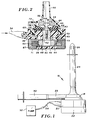
- a body implantable centrifugal pump 16 including a housing formed by joinder of an impeller casing 18 and a rotor casing 20, both casings being annular and constructed of a non-electrically conductive, biocompatible material such as polycarbonate or polysulfone.
- a titanium stator casing 22 surrounds the bottom portion of rotor casing 20, for securing an annular stator to the outside of the rotor casing.
- the stator and rotor casing bottom can be encapsulated in a plastic, e.g. a biocompatible epoxy.
- An inlet catheter or tube 24 having a plurality of inlet openings 26 receives blood or other bodily fluids into an impeller chamber defined by impeller casing 18. Bodily fluid is expelled from the chamber through an outlet tube 28 and a catheter or tube 30 connected to the outlet tube.
- Catheter 24 extends from the pump to the heart where the inlet with openings 26 extends into the left ventrical of the heart.
- Catheter 30 extends from the pump to the aorta at which point the blood returns to circulation.
- Catheters 24 and 30 are secured by Dacron grafts, cuffs or other appropriate means.
- a body implantable infusion pump 32 supplies a saline solution through a length of flexible tubing 34 to a rotor chamber formed in rotor casing 20.
- Infusion pump 32 preferably is a roller pump or a syringe pump powered by an internal battery to discharge saline at a predetermined, constant rate, for example by a continuous or stepped advance of a plunger in a manner well known and thus not further described herein.
- Implanted infusion pumps of either the constant flow type available from Infusaid or the electronic variable flow type available from Medtronic or Minimed, can be used.
- the saline solution is provided through a passageway 36 to a rotor chamber 38 formed by rotor casing 20.
- a stainless steel rotor 40 is contained to rotate within the pump housing about a vertical axis, and is generally cylindrical having an inverted T-shaped profile.
- Rotor 40 includes a cylindrical shank 42 and a shell 44 below the shank and somewhat larger in diameter.
- a disc-shaped cover 46 is secured to the shell for retaining an annular, four-pole neodymium iron (NdFe) permanent magnet 48.
- the magnet is sealed within the enclosure by welding cover 46, to separate the chemically reactive NdFe magnet from the saline solution, preventing corrosion of the magnet and contamination of the saline solution.
- Magnet 48 also is cemented in place within the shell prior to welding of the end cap to prevent free rotation of the magnet within the shell.
- Impeller casing 18 includes an inlet throat 50 received into tube 24, and forms an impeller chamber 52 in which an impeller 54 is rotatably mounted. More particularly, the impeller includes a plurality of impeller blades fixed to a vertical cylindrical impeller shaft 56, which in turn is fixed to shank 42 either by a threaded connection or an adhesive, whereby shaft 56 and impeller 54 are integral with rotor 40. The impeller, shaft and rotor further are concentric on a common axis of rotation which in Figure 2 is vertical. Shaft 56 preferably is constructed of a low temperature isotropic graphite, or alternatively polished, stainless steel. Impeller 54 is constructed of polycarbonate or polysulfone.
- Rotor guide 58 is fixed relative to rotor casing 20, and preferably is constructed of polycarbonate or polysulfone, with an interior diameter slightly larger than the shank diameter.
- the axial position of the rotor is limited by a thrust bearing 60 molded into rotor casing 20.
- Impeller chamber 52 and rotor chamber 38 are separated from one another by a flexible annular seal member 62, preferably constructed of a graphite filled elastomer, e.g. neoprene rubber, with an embedded metal annular plate 63 for increased strength and stability.
- the upper surface of the seal facing the impeller chamber is provided with a non-thrombogenic polyurethane layer 64 to prevent formation of blood clots along the surface during operation of the pump.
- Seal member 62 includes a ring seal 55 and an annular lip seal 66 immediately surrounding shaft 56. For maximum seal effectiveness at the lip seal and shaft interface, lip seal 66 and shaft 56 must be concentric.
- seal 66 and rotor guide 58 are concentrically aligned on a fixture (not shown) and fixed to one another with an adhesive. Then, impeller shaft 56 is directed through lip seal 66 and mounted in shank 42, with the shank surrounded by rotor guide 58, all prior to assembly of these members into the impeller and rotor casings. Consequently, as the rotor guide controls the radial location of shank 56, the guide likewise controls shaft 56 and maintains the shaft concentric within the lip seal.
- Rotor guide 58 and seal member 62 are fixed within the pump housing by virtue of a threaded engagement of the rotor casing and impeller casing as indicated at 68.
- a flexible ring seal 70 prevents flow of fluids into and out of the housing at the junction of the casings.
- a stator 67 including an annular iron core 69 and copper wire windings 71 about the core, surrounds the lower portion of rotor casing 20 and is maintained about the casing by stator casing 22. Electrical energy selectively supplied to windings 71 generates and alters the magnetic field in a known manner to rotate magnet 48, and thus the rotor, impeller and shaft, at a predetermined speed, e.g. in the range of about 4,000 to 7,000 rpm.
- Hall sensors 73 on the stator are used to sense the angular position of magnet 48 with respect to the stator, to control the electrical current applied to the stator coils.
- Operation of pump 32 involves two fluid paths.
- the first concerns passage of blood through inlet throat 50 into the impeller chamber, where it is expelled from the chamber through an exit conduit 72 by rotation of impeller 54.
- the second fluid path involves the constant flow of the saline solution into rotor chamber 38 through passageway 36.
- the saline solution provides a fluid lubricant between the movable rotor and shaft, and the fixed rotor casing, rotor guide and seal member.
- the saline solution provides hydrodynamic bearings between the stationary and rotating parts, e.g.
- saline solution forms an annular journal bearing between impeller shaft 56 and lip seal 66. While a saline solution is frequently preferred, other fluid lubricants compatible with bodily fluids may be used in lieu of a saline solution.
- the saline solution is caused to perfuse past lip seal 66 into the impeller chamber at a constant perfusion rate.
- the perfusion rate is equal to the rate at which the lubricant is supplied to the rotor chamber by infusion pump 32. This simplifies construction of the centrifugal pump housing in eliminating the need to provide a separate exit passage for the lubricant fluid. Moreover, it provides for positive, direct control of the saline solution seal perfusion rate through control of the infusion pump.
- seal member 62 is particularly well suited to facilitate passage of fluid lubricant upwardly into the impeller chamber, while substantially preventing passage of blood downwardly into the rotor chamber.
- seal member 62 Near lip seal 66, seal member 62 includes a narrowed annular neck 74 which allows for a slight misalignment of impeller shaft 56 with respect to the seal member, and encourages the elastic flexure or deformation of the seal necessary for lubricant perfusion.
- Lip seal 66 includes a relatively small, annular and vertical interfacing surface 76 with a diameter slightly smaller than the outer diameter of shaft 56. Consequently, in the absence of saline solution flow, the interface surface contacts impeller shaft 56 to form an annular interface between lip seal 66 and the shaft.
- a tapered surface 78 next to the interface surface is inclined away from shaft 56, in the direction towards rotor chamber 38 or downwardly as viewed in Figure 3, at an acute angle preferably less than 45 .
- an upper surface 80, on the opposite side of surface 76 and facing into impeller chamber 52, is substantially normal to the impeller shaft.
- fluid pressure exerted by saline solution between lip seal 66 and shaft 56 includes a substantial transverse component (horizontal as viewed in Figure 3) which tends to separate the lip seal from the shaft and permit flow of the lubricant past the lip seal.
- fluid pressure due to blood in the impeller chamber, acting upon upper surface 80 tends to close the seal.
- Lip seal 66 "normally" is in surface engagement with impeller shaft 56, in the sense that such surface engagement exists in the absence of lubricant perfusion. However, under pump operating conditions, a steady perfusion of saline solution provides a thin film surrounding the shaft and maintaining the lip seal in a close but spaced apart relation to the shaft.
- the seal clearance can be calculated from the following equation for flow in an annular gap:
- seal member 62 thus provides for an annular gap between shaft 56 and lip seal 66 which can vary in size responsive to lubricant fluid pressure, or can close altogether in the absence of such pressure.
- This feature provides an effective seal against entry of blood into the rotor chamber in the event the perfusion of saline is interrupted. It also reduces manufacturing cost in avoiding the strict tolerances for such passages when formed by rigid walls.
- the flexible seal facilitates adjustment of the lubricant flow rate over a wider range, limited only by the maximum advisable perfusion of saline into the blood stream, but otherwise variable for measured delivery of medication, e.g. heparin or another anticoagulant.
- FIG. 4 illustrates the use of centrifugal pump 16 as part of a system for assisting a left ventricle 82 of the heart.
- Pump 16 is implanted in the chest cavity, preferably near the heart apex, with inlet tube 24 inserted directly into the left ventricle to receive blood entering that ventricle.
- Outlet tubing 30 is inserted into the abdominal aorta above the renal arteries.
- Infusion pump 32 is outside the body as shown, or alternatively can be implanted below centrifugal pump 16, where it may be refilled with lubricant solution or medication, percutaneously with a syringe.
- a control unit 84 outside of the body, provides the necessary electrical energy over a line 86 to the stator for driving the pump.
- implantable infusion pump 32 can be replaced by a syringe or roller pump mounted within the control unit, in which case line 86 provides a conduit for the fluid lubricant as well.
- infusion pump 32 Prior to operating centrifugal pump 16, infusion pump 32 is operated to supply saline solution through tubing 34 into rotor chamber 38, in an amount sufficient to fill the rotor chamber and perfuse across the interface between the impeller shaft and lip seal.
- the lip seal and shaft are adequately lubricated prior to operating pump 16, to eliminate wear and overheating of the lip seal, shaft and proximate blood or other bodily fluid.
- Perfusion continues at a steady rate controlled by infusion pump 32 during operation of centrifugal pump 16, and thus the fluid expelled into the abdominal aorta is a combination of bodily fluid and the saline solution.
- Infusion pump 32 supplies the lubricant at a constant rate rather than at a constant pressure.
- pressure of the saline solution builds to a break pressure necessary to separate the initially contiguous shaft and lip seal, with a rapid initial saline flow reducing pressure until steady-state values for flow rate and pressure are achieved.
- Saline delivery is not pressure dependent and can be delivered at a selectively increased or decreased rate for supplying a particular medication.
- pressure in the rotary chamber, particularly near the lip seal can be monitored as a means for monitoring the lubricant fluid flow.
- a steady perfusion of saline across an interface between a rotating shaft and a flexible lip seal effectively lubricates the shaft and seal while preventing passage of blood across the seal.
Landscapes
- Engineering & Computer Science (AREA)
- Health & Medical Sciences (AREA)
- Heart & Thoracic Surgery (AREA)
- Mechanical Engineering (AREA)
- Cardiology (AREA)
- Life Sciences & Earth Sciences (AREA)
- Biomedical Technology (AREA)
- Hematology (AREA)
- Anesthesiology (AREA)
- Animal Behavior & Ethology (AREA)
- General Health & Medical Sciences (AREA)
- Public Health (AREA)
- Veterinary Medicine (AREA)
- General Engineering & Computer Science (AREA)
- Physics & Mathematics (AREA)
- Fluid Mechanics (AREA)
- External Artificial Organs (AREA)
- Structures Of Non-Positive Displacement Pumps (AREA)
Claims (17)
- System zum Fördern von Körperflüssigkeit, umfassend:
eine Pumpe (16) mit einem Gehäuse (16, 20), das eine erste Kammer (52), eine zweite Kammer (38), einen mit der ersten Kammer (52) in Fluidverbindung stehenden ersten Einlaßkanal (50) zum Zulassen von Körperflüssigkeit in die erste Kammer (52), einen mit der ersten Kammer (52) in Fluidverbindung stehenden ersten Auslaßkanal (72) zum Austreiben der Körperflüssigkeit aus der ersten Kammer (52) und einen mit der zweiten Kammer (38) in Fluidverbindung stehenden zweiten Einlaßkanal (36) zum Zulassen eines flüssigen Schmiermittels in die zweite Kammer (38) aufweist, wobei das Schmiermittel biologisch kompatibel und in der Körperflüssigkeit löslich ist,
ein in der ersten Kammer (52) drehbar gelagertes Flügelrad (54), einen in der zweiten Kammer (38) drehbar gelagerten Rotor (40) und eine zylindrische Welle (56) zum Verbinden des Flügelrads (54) für Drehung in Abhängigkeit von einer Drehung des Rotors (40),
ein elastisch verformbares, am Gehäuse befestigtes und zwischen erster Kammer (52) und zweiter Kammer (38) angeordnetes Dicht(ungs)mittel (62) mit einer flexiblen Lippendichtung (66), welche die Welle unter Bildung eines ringförmigen Grenzflächenbereichs (76) im Bereich (nahe) der Welle (56) umgibt, welches Dichtmittel (62) normalerweise längs der Grenzfläche mit der Welle (56) in Flächenberührung steht,
eine Speiseeinheit (32) zum Zuspeisen des Schmiermittels über den zweiten Einlaßkanal (36) in die zweite Kammer (38) sowie eine Antriebseinrichtung (67) zum Rotierenlassen des Rotors (40) zwecks Förderung der Körperflüssigkeit durch die erste Kammer (52) sowie die ersten Einlaß- und Auslaßkanäle (50, 72),
dadurch gekennzeichnet, daß die Lippendichtung (66) im Bereich (nahe) der Grenzfläche eine konische Fläche (78) aufweist, die in einer Richtung zur zweiten Kammer (38) hin geneigt ist und mit der Welle (56) einen spitzen Winkel festlegt, und die zweite Kammer (38) so ausgebildet ist, daß dann, wenn die Speiseeinheit (32) das Schmiermittel über den zweiten Einlaßkanal (36) mit einer ersten vorbestimmten, konstanten Fluidströmungsmenge oder -geschwindigkeit in die zweite Kammer (38) einspeist, ein Durchströmen (perfusion) des Schmiermittels längs der Grenzfläche und in die erste Kammer (52) mit einer zweiten konstanten Fluidströmungsmenge oder -geschwindigkeit herbeigeführt wird, so daß das Dichtmittel (62) elastisch verformt und gegen eine Rückstellkraft im (des) Dichtmittel(s) (62), welche zur Wiederherstellung der Flächenberührung bestrebt ist, in naher, aber beabstandeter Beziehung zur Welle (56) gehalten wird, solange die Durchströmung andauert. - System nach Anspruch 1, wobei
die zylindrische Welle (56) am Flügelrad (54) und am Rotor (40) angebracht und auf einer gemeinsamen Drehachse konzentrisch zu Flügelrad (54) und Rotor (40) angeordnet ist. - System nach Anspruch 1 oder 2, wobei
die ringförmige Grenzfläche praktisch das einzige Mittel für einen Durchtritt des Schmiermittels aus der zweiten Kammer (38) heraus darstellt und die ersten und zweiten konstanten Fluidströmungsmengen (oder -geschwindigkeiten) praktisch gleich groß sind. - System nach einem der vorangehenden Ansprüche, wobei
die ersten und zweiten konstanten Fluidströmunasmengen (oder -geschwindigkeiten) im Bereich von etwa 0,5 - 1000 ml pro 24 h liegen. - System nach Anspruch 4, wobei
die ersten und zweiten konstanten Fluidströmungsmengen (oder -geschwindigkeiten) etwa 10 ml pro 24 h betragen. - System nach einem der vorangehenden Ansprüche, wobei
die Lippendichtung (66) ferner eine einer Kammer zugewandte Fläche neben bzw. an der (dem) Wellen-Grenzfläche(nbereich) an der der konischen Fläche gegenüberliegenden Seite aufweist, welche Fläche einen Winkel von etwa 90° mit der (dem) Grenzfläche(nbereich) festlegt. - System nach einem der vorangehenden Ansprüche, wobei
das Gehäuse einen im wesentlichen steifen, das Flügelrad (54) und das Dichtmittel (62) umschließenden Flügelradgehäuseteil (18) und einen im wesentlichen steifen, den Rotor (40) umschließenden Rotorgehäuseteil (20) umfaßt. - System nach Anspruch 7, wobei
der Flügelradgehäuseteil (18) und der Rotorgehäuseteil (20) miteinander verschraubt sind. - System nach Anspruch 7 oder 8, ferner umfassend:
ein im wesentlichen steifes, ringförmiges Rotor-Führungselement (58), wobei der Rotor einen zylindrischen Schaft (42), der zur Welle (56) konzentrisch angeordnet ist und diese aufnimmt, und ein einschließendes Segment (44) eines Durchmessers, der größer ist als derjenige des Schafts (56) (bzw. 42 - A.d.Ü.) aufweist, wobei das Führungselement (58) eine zylindrische Öffnung aufweist, die geringfügig größer ist als der Durchmesser des Schafts (42), und wobei das Führungselement (58) ferner im Rotorgehäuse (20) montiert und mit diesem integriert ist und den Schaft (42) umgibt. - System nach Anspruch 9, wobei
das Dichtmittel (62) eine einheitliche oder einstückige ringförmige Dichtung ist, welche die erste Kammer (52) praktisch überspannt. - System nach Anspruch 10, wobei
die Dichtung (62) und das Führungselement (58) vor ihrem Einbau in das Gehäuse aneinander befestigt werden (worden sind), um sie axial miteinander auszufluchten. - System nach Anspruch 9, 10 oder 11, wobei
das einschließende Segment (44) des Rotors (40) einen ringförmigen Dauermagneten (48) enthält und wobei die Antriebseinrichtung ein Stator (67) ist, der gegenüber dem Rotorgehäuse (20) (fest) montiert und nahe dem einschließenden Segment (44) angeordnet ist. - System nach Anspruch 12, wobei
der Stator (67) ringförmig ist und das einschließende Segment (44) umgibt. - System nach Anspruch 12 oder 13, wobei
der Stator (67) das Rotorgehäuse (20) umgibt und an dessen Außenseite fest montiert ist. - System nach Anspruch 2, wobei
die Speiseeinheit eine in einen Körper implantierbare Perfusions- bzw. Infusionspumpe (32) mit einem Mittel zum Aufnehmen eines Vorrats des Schmiermittels und ausgelegt, um im Gebrauch das Schmiermittel perkutan aufzunehmen, und ein Leitungsmittel (34) zum Fördern des Schmiermittels aus dem Aufnahmemittel zum zweiten Einlaßkanal (36) mit der ersten Fluidströmungsmenge (oder -geschwindigkeit) in Abhängigkeit vom Betrieb der Infusionspumpe ist. - System nach Anspruch 15, wobei
die Schmiermittel-Speiseeinheit eine Rollenpumpe oder eine Spritzenpumpe umfaßt. - System nach einem der Ansprüche 1 bis 14, wobei die Schmiermittel-Speiseeinheit eine Infusionspumpe (32) und einen Schmiermittelvorrat außerhalb des Körpers und ein Leitungsmittel (34) zum Fördern von Schmiermittel vom Schmiermittelvorrat zum zweiten Einlaßkanal (36) mit der ersten Strömungsmenge (oder -geschwindigkeit) in Abhängigkeit vom Betrieb der Infusionspumpe (32) aufweist.
Applications Claiming Priority (3)
| Application Number | Priority Date | Filing Date | Title |
|---|---|---|---|
| US367960 | 1989-06-19 | ||
| US07/367,960 US4927407A (en) | 1989-06-19 | 1989-06-19 | Cardiac assist pump with steady rate supply of fluid lubricant |
| PCT/US1990/003395 WO1990015640A1 (en) | 1989-06-19 | 1990-06-18 | Cardiac assist pump |
Publications (3)
| Publication Number | Publication Date |
|---|---|
| EP0478635A1 EP0478635A1 (de) | 1992-04-08 |
| EP0478635A4 EP0478635A4 (en) | 1992-05-06 |
| EP0478635B1 true EP0478635B1 (de) | 1994-12-07 |
Family
ID=23449318
Family Applications (1)
| Application Number | Title | Priority Date | Filing Date |
|---|---|---|---|
| EP90909556A Expired - Lifetime EP0478635B1 (de) | 1989-06-19 | 1990-06-18 | Beihilfepumpe für das herz |
Country Status (6)
| Country | Link |
|---|---|
| US (1) | US4927407A (de) |
| EP (1) | EP0478635B1 (de) |
| JP (1) | JPH04506163A (de) |
| AT (1) | ATE114976T1 (de) |
| DE (1) | DE69014884T2 (de) |
| WO (1) | WO1990015640A1 (de) |
Cited By (16)
| Publication number | Priority date | Publication date | Assignee | Title |
|---|---|---|---|---|
| US6858001B1 (en) | 1997-07-11 | 2005-02-22 | A-Med Systems, Inc. | Single port cardiac support apparatus |
| US7182727B2 (en) | 1997-07-11 | 2007-02-27 | A—Med Systems Inc. | Single port cardiac support apparatus |
| CN108778358A (zh) * | 2016-01-06 | 2018-11-09 | 毕瓦克公司 | 心脏泵 |
| US10722631B2 (en) | 2018-02-01 | 2020-07-28 | Shifamed Holdings, Llc | Intravascular blood pumps and methods of use and manufacture |
| US11185677B2 (en) | 2017-06-07 | 2021-11-30 | Shifamed Holdings, Llc | Intravascular fluid movement devices, systems, and methods of use |
| US11511103B2 (en) | 2017-11-13 | 2022-11-29 | Shifamed Holdings, Llc | Intravascular fluid movement devices, systems, and methods of use |
| US11654275B2 (en) | 2019-07-22 | 2023-05-23 | Shifamed Holdings, Llc | Intravascular blood pumps with struts and methods of use and manufacture |
| US11724089B2 (en) | 2019-09-25 | 2023-08-15 | Shifamed Holdings, Llc | Intravascular blood pump systems and methods of use and control thereof |
| US11964145B2 (en) | 2019-07-12 | 2024-04-23 | Shifamed Holdings, Llc | Intravascular blood pumps and methods of manufacture and use |
| US12102815B2 (en) | 2019-09-25 | 2024-10-01 | Shifamed Holdings, Llc | Catheter blood pumps and collapsible pump housings |
| US12121713B2 (en) | 2019-09-25 | 2024-10-22 | Shifamed Holdings, Llc | Catheter blood pumps and collapsible blood conduits |
| US12161857B2 (en) | 2018-07-31 | 2024-12-10 | Shifamed Holdings, Llc | Intravascular blood pumps and methods of use |
| US12220570B2 (en) | 2018-10-05 | 2025-02-11 | Shifamed Holdings, Llc | Intravascular blood pumps and methods of use |
| US12409310B2 (en) | 2019-12-11 | 2025-09-09 | Shifamed Holdings, Llc | Descending aorta and vena cava blood pumps |
| US12465748B2 (en) | 2019-08-07 | 2025-11-11 | Supira Medical, Inc. | Catheter blood pumps and collapsible pump housings |
| US12599758B2 (en) | 2019-12-19 | 2026-04-14 | Shifamed Holdings, Llc | Intravascular blood pumps, motors, and fluid control |
Families Citing this family (183)
| Publication number | Priority date | Publication date | Assignee | Title |
|---|---|---|---|---|
| US5098256A (en) * | 1989-11-21 | 1992-03-24 | The Cleveland Clinic Foundation | Viscous seal blood pump |
| US5118264A (en) * | 1990-01-11 | 1992-06-02 | The Cleveland Clinic Foundation | Purge flow control in rotary blood pumps |
| US5145333A (en) * | 1990-03-01 | 1992-09-08 | The Cleveland Clinic Foundation | Fluid motor driven blood pump |
| US5471965A (en) * | 1990-12-24 | 1995-12-05 | Kapich; Davorin D. | Very high speed radial inflow hydraulic turbine |
| DE4105278C2 (de) * | 1991-02-20 | 1995-04-20 | Rau Guenter | Blutpumpe als Kreiselpumpe |
| US5730722A (en) * | 1992-08-19 | 1998-03-24 | Wilk; Peter J. | Method and apparatus for supplying a medical treatment composition to a patient |
| JPH0669492B2 (ja) * | 1992-08-20 | 1994-09-07 | 日機装株式会社 | 血液ポンプ |
| US5376114A (en) * | 1992-10-30 | 1994-12-27 | Jarvik; Robert | Cannula pumps for temporary cardiac support and methods of their application and use |
| JPH06346917A (ja) * | 1993-06-03 | 1994-12-20 | Shicoh Eng Co Ltd | 一方向性動圧軸受を用いた耐圧防水シ−ル機構 |
| US5531789A (en) * | 1993-12-24 | 1996-07-02 | Sun Medical Technology Research Corporation | Sealing system of an artificial internal organ |
| EP1402908A3 (de) * | 1994-04-15 | 2005-04-27 | Allegheny-Singer Research Institute | Blutpumpe und Herstellungsverfahren |
| JP2760283B2 (ja) * | 1994-06-24 | 1998-05-28 | 株式会社ツムラ | 動物用のアダプタ |
| US5695471A (en) * | 1996-02-20 | 1997-12-09 | Kriton Medical, Inc. | Sealless rotary blood pump with passive magnetic radial bearings and blood immersed axial bearings |
| US5810758A (en) * | 1996-05-23 | 1998-09-22 | Sun Medical Technology Research Corporation | Purge solution circulating apparatus for artificial organ |
| US5851174A (en) * | 1996-09-17 | 1998-12-22 | Robert Jarvik | Cardiac support device |
| US5965089A (en) | 1996-10-04 | 1999-10-12 | United States Surgical Corporation | Circulatory support system |
| SE9700384D0 (sv) * | 1997-02-04 | 1997-02-04 | Biacore Ab | Analytical method and apparatus |
| US8527026B2 (en) | 1997-03-04 | 2013-09-03 | Dexcom, Inc. | Device and method for determining analyte levels |
| US7657297B2 (en) | 2004-05-03 | 2010-02-02 | Dexcom, Inc. | Implantable analyte sensor |
| US7192450B2 (en) | 2003-05-21 | 2007-03-20 | Dexcom, Inc. | Porous membranes for use with implantable devices |
| US6862465B2 (en) | 1997-03-04 | 2005-03-01 | Dexcom, Inc. | Device and method for determining analyte levels |
| US20050033132A1 (en) | 1997-03-04 | 2005-02-10 | Shults Mark C. | Analyte measuring device |
| US6001067A (en) | 1997-03-04 | 1999-12-14 | Shults; Mark C. | Device and method for determining analyte levels |
| US6048363A (en) * | 1997-05-13 | 2000-04-11 | Nagyszalanczy; Lorant | Centrifugal blood pump apparatus |
| US6532964B2 (en) | 1997-07-11 | 2003-03-18 | A-Med Systems, Inc. | Pulmonary and circulatory blood flow support devices and methods for heart surgery procedures |
| WO1999004834A1 (en) * | 1997-07-25 | 1999-02-04 | Sun Medical Technology Research Corporation | Portable drive system for artificial heart |
| US6387037B1 (en) | 1997-10-09 | 2002-05-14 | Orqis Medical Corporation | Implantable heart assist system and method of applying same |
| US6610004B2 (en) * | 1997-10-09 | 2003-08-26 | Orqis Medical Corporation | Implantable heart assist system and method of applying same |
| US6390969B1 (en) | 1997-10-09 | 2002-05-21 | Orqis Medical Corporation | Implantable heart assist system and method of applying same |
| UA56262C2 (uk) | 1997-10-09 | 2003-05-15 | Орквіс Медікел Корпорейшн | Імплантовувана система підтримки серця |
| US6889082B2 (en) * | 1997-10-09 | 2005-05-03 | Orqis Medical Corporation | Implantable heart assist system and method of applying same |
| US5928131A (en) * | 1997-11-26 | 1999-07-27 | Vascor, Inc. | Magnetically suspended fluid pump and control system |
| US6422990B1 (en) | 1997-11-26 | 2002-07-23 | Vascor, Inc. | Blood pump flow rate control method and apparatus utilizing multiple sensors |
| US6293901B1 (en) | 1997-11-26 | 2001-09-25 | Vascor, Inc. | Magnetically suspended fluid pump and control system |
| US9066695B2 (en) | 1998-04-30 | 2015-06-30 | Abbott Diabetes Care Inc. | Analyte monitoring device and methods of use |
| US8346337B2 (en) | 1998-04-30 | 2013-01-01 | Abbott Diabetes Care Inc. | Analyte monitoring device and methods of use |
| US8688188B2 (en) | 1998-04-30 | 2014-04-01 | Abbott Diabetes Care Inc. | Analyte monitoring device and methods of use |
| US8480580B2 (en) | 1998-04-30 | 2013-07-09 | Abbott Diabetes Care Inc. | Analyte monitoring device and methods of use |
| US6175752B1 (en) | 1998-04-30 | 2001-01-16 | Therasense, Inc. | Analyte monitoring device and methods of use |
| US6949816B2 (en) | 2003-04-21 | 2005-09-27 | Motorola, Inc. | Semiconductor component having first surface area for electrically coupling to a semiconductor chip and second surface area for electrically coupling to a substrate, and method of manufacturing same |
| US8465425B2 (en) | 1998-04-30 | 2013-06-18 | Abbott Diabetes Care Inc. | Analyte monitoring device and methods of use |
| US8974386B2 (en) | 1998-04-30 | 2015-03-10 | Abbott Diabetes Care Inc. | Analyte monitoring device and methods of use |
| US7780628B1 (en) | 1999-01-11 | 2010-08-24 | Angiodynamics, Inc. | Apparatus and methods for treating congestive heart disease |
| US7481803B2 (en) * | 2000-11-28 | 2009-01-27 | Flowmedica, Inc. | Intra-aortic renal drug delivery catheter |
| US6749598B1 (en) | 1999-01-11 | 2004-06-15 | Flowmedica, Inc. | Apparatus and methods for treating congestive heart disease |
| US7329236B2 (en) * | 1999-01-11 | 2008-02-12 | Flowmedica, Inc. | Intra-aortic renal drug delivery catheter |
| US7122019B1 (en) | 2000-11-28 | 2006-10-17 | Flowmedica Inc. | Intra-aortic renal drug delivery catheter |
| NL1022038C2 (nl) | 1999-02-09 | 2003-07-25 | Vascor Inc | Bloedpomp met magnetisch opgehangen stator- en rotorelement met een eerste en tweede magneet-array. |
| US6514226B1 (en) * | 2000-02-10 | 2003-02-04 | Chf Solutions, Inc. | Method and apparatus for treatment of congestive heart failure by improving perfusion of the kidney |
| US6808508B1 (en) * | 2000-09-13 | 2004-10-26 | Cardiacassist, Inc. | Method and system for closed chest blood flow support |
| US6560471B1 (en) | 2001-01-02 | 2003-05-06 | Therasense, Inc. | Analyte monitoring device and methods of use |
| AU2002309528A1 (en) | 2001-04-02 | 2002-10-15 | Therasense, Inc. | Blood glucose tracking apparatus and methods |
| US6702857B2 (en) | 2001-07-27 | 2004-03-09 | Dexcom, Inc. | Membrane for use with implantable devices |
| US20030032874A1 (en) | 2001-07-27 | 2003-02-13 | Dexcom, Inc. | Sensor head for use with implantable devices |
| JP5046449B2 (ja) * | 2001-08-10 | 2012-10-10 | 株式会社サンメディカル技術研究所 | 血液ポンプ |
| US8010174B2 (en) | 2003-08-22 | 2011-08-30 | Dexcom, Inc. | Systems and methods for replacing signal artifacts in a glucose sensor data stream |
| US8260393B2 (en) | 2003-07-25 | 2012-09-04 | Dexcom, Inc. | Systems and methods for replacing signal data artifacts in a glucose sensor data stream |
| US9247901B2 (en) | 2003-08-22 | 2016-02-02 | Dexcom, Inc. | Systems and methods for replacing signal artifacts in a glucose sensor data stream |
| US9282925B2 (en) | 2002-02-12 | 2016-03-15 | Dexcom, Inc. | Systems and methods for replacing signal artifacts in a glucose sensor data stream |
| US7226978B2 (en) | 2002-05-22 | 2007-06-05 | Dexcom, Inc. | Techniques to improve polyurethane membranes for implantable glucose sensors |
| US20060258761A1 (en) * | 2002-05-22 | 2006-11-16 | Robert Boock | Silicone based membranes for use in implantable glucose sensors |
| AU2003294226A1 (en) * | 2002-09-20 | 2004-04-23 | Flowmedica, Inc. | Method and apparatus for intra aortic substance delivery to a branch vessel |
| US7063679B2 (en) | 2002-09-20 | 2006-06-20 | Flowmedica, Inc. | Intra-aortic renal delivery catheter |
| US7993325B2 (en) | 2002-09-20 | 2011-08-09 | Angio Dynamics, Inc. | Renal infusion systems and methods |
| US7585836B2 (en) | 2004-05-14 | 2009-09-08 | Goodson Iv Harry Burt | Bi-lateral local renal delivery for treating congestive heart failure and for BNP therapy |
| WO2004032791A2 (en) * | 2002-09-20 | 2004-04-22 | Flowmedica, Inc. | Method and apparatus for selective material delivery via an intra-renal catheter |
| EP1624909A2 (de) * | 2002-09-20 | 2006-02-15 | FlowMedica, Inc. | Gerät und verfahren zur einführung eines intraaortakalen katheters durch eine ablageschleuse |
| US20050197624A1 (en) * | 2004-03-04 | 2005-09-08 | Flowmedica, Inc. | Sheath for use in peripheral interventions |
| US7134999B2 (en) * | 2003-04-04 | 2006-11-14 | Dexcom, Inc. | Optimized sensor geometry for an implantable glucose sensor |
| US7875293B2 (en) | 2003-05-21 | 2011-01-25 | Dexcom, Inc. | Biointerface membranes incorporating bioactive agents |
| EP1635736A2 (de) * | 2003-06-05 | 2006-03-22 | FlowMedica, Inc. | Systeme und verfahren zur durchführung von bilateralen interventionen oder diagnose in verzweigten körperlumen |
| US20060167437A1 (en) * | 2003-06-17 | 2006-07-27 | Flowmedica, Inc. | Method and apparatus for intra aortic substance delivery to a branch vessel |
| US7761130B2 (en) | 2003-07-25 | 2010-07-20 | Dexcom, Inc. | Dual electrode system for a continuous analyte sensor |
| WO2005012873A2 (en) | 2003-07-25 | 2005-02-10 | Dexcom, Inc. | Electrode systems for electrochemical sensors |
| US20050056552A1 (en) * | 2003-07-25 | 2005-03-17 | Simpson Peter C. | Increasing bias for oxygen production in an electrode system |
| US20050176136A1 (en) * | 2003-11-19 | 2005-08-11 | Dexcom, Inc. | Afinity domain for analyte sensor |
| US7519408B2 (en) | 2003-11-19 | 2009-04-14 | Dexcom, Inc. | Integrated receiver for continuous analyte sensor |
| US8160669B2 (en) | 2003-08-01 | 2012-04-17 | Dexcom, Inc. | Transcutaneous analyte sensor |
| US20100168542A1 (en) | 2003-08-01 | 2010-07-01 | Dexcom, Inc. | System and methods for processing analyte sensor data |
| US8845536B2 (en) | 2003-08-01 | 2014-09-30 | Dexcom, Inc. | Transcutaneous analyte sensor |
| US8761856B2 (en) | 2003-08-01 | 2014-06-24 | Dexcom, Inc. | System and methods for processing analyte sensor data |
| US7774145B2 (en) | 2003-08-01 | 2010-08-10 | Dexcom, Inc. | Transcutaneous analyte sensor |
| US7591801B2 (en) | 2004-02-26 | 2009-09-22 | Dexcom, Inc. | Integrated delivery device for continuous glucose sensor |
| US20190357827A1 (en) | 2003-08-01 | 2019-11-28 | Dexcom, Inc. | Analyte sensor |
| US8275437B2 (en) | 2003-08-01 | 2012-09-25 | Dexcom, Inc. | Transcutaneous analyte sensor |
| US7778680B2 (en) | 2003-08-01 | 2010-08-17 | Dexcom, Inc. | System and methods for processing analyte sensor data |
| EP1659970A4 (de) * | 2003-08-05 | 2008-05-21 | Flowmedica Inc | System und verfahren zur prävention von radiokontrast-induzierter nephropathie |
| US8233959B2 (en) | 2003-08-22 | 2012-07-31 | Dexcom, Inc. | Systems and methods for processing analyte sensor data |
| US20140121989A1 (en) | 2003-08-22 | 2014-05-01 | Dexcom, Inc. | Systems and methods for processing analyte sensor data |
| US7920906B2 (en) | 2005-03-10 | 2011-04-05 | Dexcom, Inc. | System and methods for processing analyte sensor data for sensor calibration |
| US20050085683A1 (en) * | 2003-10-15 | 2005-04-21 | Bolling Steven F. | Implantable heart assist system and method of applying same |
| US9247900B2 (en) | 2004-07-13 | 2016-02-02 | Dexcom, Inc. | Analyte sensor |
| US8423114B2 (en) | 2006-10-04 | 2013-04-16 | Dexcom, Inc. | Dual electrode system for a continuous analyte sensor |
| US8774886B2 (en) | 2006-10-04 | 2014-07-08 | Dexcom, Inc. | Analyte sensor |
| EP2239567B1 (de) | 2003-12-05 | 2015-09-02 | DexCom, Inc. | Kalibrierverfahren für einen kontinuierlichen Analytsensor |
| US11633133B2 (en) | 2003-12-05 | 2023-04-25 | Dexcom, Inc. | Dual electrode system for a continuous analyte sensor |
| US8364231B2 (en) | 2006-10-04 | 2013-01-29 | Dexcom, Inc. | Analyte sensor |
| US7081195B2 (en) * | 2003-12-08 | 2006-07-25 | Dexcom, Inc. | Systems and methods for improving electrochemical analyte sensors |
| EP2316331B1 (de) | 2003-12-09 | 2016-06-29 | Dexcom, Inc. | Signalverarbeitung in einem durchgehenden Analytsensor |
| US20050131385A1 (en) * | 2003-12-12 | 2005-06-16 | Bolling Steven F. | Cannulae for selectively enhancing blood flow |
| US7637868B2 (en) * | 2004-01-12 | 2009-12-29 | Dexcom, Inc. | Composite material for implantable device |
| US20050182451A1 (en) * | 2004-01-12 | 2005-08-18 | Adam Griffin | Implantable device with improved radio frequency capabilities |
| WO2005079257A2 (en) * | 2004-02-12 | 2005-09-01 | Dexcom, Inc. | Biointerface with macro- and micro- architecture |
| US8808228B2 (en) | 2004-02-26 | 2014-08-19 | Dexcom, Inc. | Integrated medicament delivery device for use with continuous analyte sensor |
| US8277713B2 (en) | 2004-05-03 | 2012-10-02 | Dexcom, Inc. | Implantable analyte sensor |
| US8792955B2 (en) | 2004-05-03 | 2014-07-29 | Dexcom, Inc. | Transcutaneous analyte sensor |
| US20050245799A1 (en) * | 2004-05-03 | 2005-11-03 | Dexcom, Inc. | Implantable analyte sensor |
| US20050277870A1 (en) * | 2004-06-10 | 2005-12-15 | Robert Pecor | Cannula having reduced flow resistance |
| US7445592B2 (en) * | 2004-06-10 | 2008-11-04 | Orqis Medical Corporation | Cannulae having reduced flow resistance |
| US8989833B2 (en) | 2004-07-13 | 2015-03-24 | Dexcom, Inc. | Transcutaneous analyte sensor |
| US8565848B2 (en) * | 2004-07-13 | 2013-10-22 | Dexcom, Inc. | Transcutaneous analyte sensor |
| US8452368B2 (en) | 2004-07-13 | 2013-05-28 | Dexcom, Inc. | Transcutaneous analyte sensor |
| WO2006127694A2 (en) | 2004-07-13 | 2006-11-30 | Dexcom, Inc. | Analyte sensor |
| US7857760B2 (en) | 2004-07-13 | 2010-12-28 | Dexcom, Inc. | Analyte sensor |
| US20060069323A1 (en) * | 2004-09-24 | 2006-03-30 | Flowmedica, Inc. | Systems and methods for bi-lateral guidewire cannulation of branched body lumens |
| US7699586B2 (en) | 2004-12-03 | 2010-04-20 | Heartware, Inc. | Wide blade, axial flow pump |
| US8419609B2 (en) | 2005-10-05 | 2013-04-16 | Heartware Inc. | Impeller for a rotary ventricular assist device |
| US7972122B2 (en) * | 2005-04-29 | 2011-07-05 | Heartware, Inc. | Multiple rotor, wide blade, axial flow pump |
| US20060184199A1 (en) * | 2005-02-14 | 2006-08-17 | O'leary Shawn | Apparatus and methods for reducing bleeding from a cannulation site |
| US20060224110A1 (en) * | 2005-03-17 | 2006-10-05 | Scott Michael J | Methods for minimally invasive vascular access |
| US8060174B2 (en) | 2005-04-15 | 2011-11-15 | Dexcom, Inc. | Analyte sensing biointerface |
| WO2007004550A1 (ja) * | 2005-07-06 | 2007-01-11 | Komatsu Denshi Kinzoku Kabushiki Kaisha | 半導体ウェーハの製造方法および製造装置 |
| WO2007040663A1 (en) * | 2005-10-05 | 2007-04-12 | Heartware, Inc. | Axial flow pump with multi-grooved rotor |
| JP2009511199A (ja) * | 2005-10-11 | 2009-03-19 | フロウメディカ, インコーポレイテッド | 可変管腔構成の血管シース |
| US8550973B2 (en) * | 2006-01-09 | 2013-10-08 | Cardiacassist, Inc. | Percutaneous right ventricular assist apparatus and method |
| JP2009530041A (ja) | 2006-03-23 | 2009-08-27 | ザ・ペン・ステート・リサーチ・ファンデーション | 拡張可能なインペラポンプを有する心臓補助装置 |
| US20080071158A1 (en) | 2006-06-07 | 2008-03-20 | Abbott Diabetes Care, Inc. | Analyte monitoring system and method |
| US7771401B2 (en) * | 2006-06-08 | 2010-08-10 | Angiodynamics, Inc. | Selective renal cannulation and infusion systems and methods |
| AU2008219653B2 (en) | 2007-02-26 | 2014-01-16 | Heartware, Inc. | Intravascular ventricular assist device |
| WO2008112563A1 (en) * | 2007-03-09 | 2008-09-18 | Flowmedica, Inc. | Acute kidney injury treatment systems and methods |
| US20080306434A1 (en) | 2007-06-08 | 2008-12-11 | Dexcom, Inc. | Integrated medicament delivery device for use with continuous analyte sensor |
| EP2227132B1 (de) | 2007-10-09 | 2023-03-08 | DexCom, Inc. | Integriertes insulin-abgabesystem mit kontinuierlichem glucosesensor |
| US20090105799A1 (en) * | 2007-10-23 | 2009-04-23 | Flowmedica, Inc. | Renal assessment systems and methods |
| US8417312B2 (en) | 2007-10-25 | 2013-04-09 | Dexcom, Inc. | Systems and methods for processing sensor data |
| EP2249746B1 (de) | 2008-02-08 | 2018-10-03 | Heartware, Inc. | Ventrikuläres unterstützungssystem zur intraventrikulären platzierung |
| US8591455B2 (en) | 2008-02-21 | 2013-11-26 | Dexcom, Inc. | Systems and methods for customizing delivery of sensor data |
| EP2106784B1 (de) * | 2008-04-03 | 2015-04-22 | Rohm and Haas Company | Haarstylingzusammensetzung |
| DE102008037760B4 (de) * | 2008-08-14 | 2015-12-24 | MTU Aero Engines AG | Werkstoffprobe, Werkstoffprobenaufbau und Werkstoffprüfmaschine sowie Verfahren zum Test von biaxialen Spannungszuständen |
| US8562519B2 (en) | 2009-12-31 | 2013-10-22 | Cardiacassist, Inc. | Pumping system and method for assisting a patient's heart |
| US9848809B2 (en) | 2011-04-15 | 2017-12-26 | Dexcom, Inc. | Advanced analyte sensor calibration and error detection |
| CA2869321A1 (en) * | 2012-04-06 | 2013-10-10 | Heartware, Inc. | Ambulatory lung assist device with implanted blood pump and oxygenator |
| DE102013008168A1 (de) | 2012-05-14 | 2013-11-14 | Thoratec Corporation | Laufrad für Katheterpumpe |
| DE102013008159A1 (de) | 2012-05-14 | 2013-11-14 | Thoratec Corporation | Mantelsystem für Katheterpumpe |
| US9446179B2 (en) | 2012-05-14 | 2016-09-20 | Thoratec Corporation | Distal bearing support |
| US9358329B2 (en) | 2012-07-03 | 2016-06-07 | Thoratec Corporation | Catheter pump |
| JP6530367B2 (ja) | 2013-03-13 | 2019-06-12 | ティーシーワン エルエルシー | 流体導出入システム |
| JP5899528B2 (ja) * | 2014-02-19 | 2016-04-06 | 株式会社サンメディカル技術研究所 | 摺動装置、メカニカルシール、ポンプ及び補助人工心臓システム |
| WO2015160980A1 (en) | 2014-04-15 | 2015-10-22 | Thoratec Corporation | Heart pump providing adjustable out flow |
| US10583232B2 (en) | 2014-04-15 | 2020-03-10 | Tc1 Llc | Catheter pump with off-set motor position |
| US10744255B2 (en) | 2014-07-22 | 2020-08-18 | Heartware, Inc. | Cardiac support system and methods |
| WO2016118777A1 (en) * | 2015-01-22 | 2016-07-28 | Thoratec Corporation | Reduced rotational mass motor assembly for catheter pump |
| US10029038B2 (en) | 2015-07-21 | 2018-07-24 | Tc1 Llc | Cantilevered rotor pump and methods for axial flow blood pumping |
| US11160970B2 (en) | 2016-07-21 | 2021-11-02 | Tc1 Llc | Fluid seals for catheter pump motor assembly |
| WO2018017716A1 (en) | 2016-07-21 | 2018-01-25 | Tc1 Llc | Rotary seal for cantilevered rotor pump and methods for axial flow blood pumping |
| US11331022B2 (en) | 2017-10-24 | 2022-05-17 | Dexcom, Inc. | Pre-connected analyte sensors |
| EP3928687B1 (de) | 2017-10-24 | 2024-06-26 | Dexcom, Inc. | Tragbare vorrichtung mit vorverbundenem analytsensor |
| DE102018201030B4 (de) | 2018-01-24 | 2025-10-16 | Kardion Gmbh | Magnetkuppelelement mit magnetischer Lagerungsfunktion |
| DE102018207594A1 (de) | 2018-05-16 | 2019-11-21 | Kardion Gmbh | Rotor, Magnetkupplungsvorrichtung, Elektromotor für ein Herzunterstützungssystem, Pumpeneinheit für ein Herzunterstützungssystem sowie Verfahren zum Herstellen eines Rotors |
| DE102018207611A1 (de) | 2018-05-16 | 2019-11-21 | Kardion Gmbh | Rotorlagerungssystem |
| DE102018207575A1 (de) | 2018-05-16 | 2019-11-21 | Kardion Gmbh | Magnetische Stirndreh-Kupplung zur Übertragung von Drehmomenten |
| DE102018208541A1 (de) | 2018-05-30 | 2019-12-05 | Kardion Gmbh | Axialpumpe für ein Herzunterstützungssystem und Verfahren zum Herstellen einer Axialpumpe für ein Herzunterstützungssystem |
| DE102018208549A1 (de) | 2018-05-30 | 2019-12-05 | Kardion Gmbh | Elektronikmodul für ein Herzunterstützungssystem und Verfahren zum Herstellen eines Elektronikmoduls für ein Herzunterstützungssystem |
| DE102018208550A1 (de) | 2018-05-30 | 2019-12-05 | Kardion Gmbh | Leitungsvorrichtung zum Leiten eines Blutstroms für ein Herzunterstützungssystem, Herzunterstützungssystem und Verfahren zum Herstellen einer Leitungsvorrichtung |
| DE102018208538A1 (de) | 2018-05-30 | 2019-12-05 | Kardion Gmbh | Intravasale Blutpumpe und Verfahren zur Herstellung von elektrischen Leiterbahnen |
| DE102018208539A1 (de) | 2018-05-30 | 2019-12-05 | Kardion Gmbh | Motorgehäusemodul zum Abdichten eines Motorraums eines Motors eines Herzunterstützungssystems und Herzunterstützungssystem und Verfahren zum Montieren eines Herzunterstützungssystems |
| DE102018210058A1 (de) | 2018-06-21 | 2019-12-24 | Kardion Gmbh | Statorschaufelvorrichtung zur Strömungsführung eines aus einer Austrittsöffnung eines Herzunterstützungssystems ausströmenden Fluids, Herzunterstützungssystem mit Statorschaufelvorrichtung, Verfahren zum Betreiben einer Statorschaufelvorrichtung und Herstellverfahren |
| DE102018210076A1 (de) | 2018-06-21 | 2019-12-24 | Kardion Gmbh | Verfahren und Vorrichtung zum Erkennen eines Verschleißzustands eines Herzunterstützungssystems, Verfahren und Vorrichtung zum Betreiben eines Herzunterstützungssystems und Herzunterstützungssystem |
| DE102018211297A1 (de) | 2018-07-09 | 2020-01-09 | Kardion Gmbh | Herzunterstützungssystem und Verfahren zur Überwachung der Integrität einer Haltestruktur eines Herzunterstützungssystems |
| DE102018211327A1 (de) | 2018-07-10 | 2020-01-16 | Kardion Gmbh | Laufrad für ein implantierbares, vaskuläres Unterstützungssystem |
| DE102018211328A1 (de) | 2018-07-10 | 2020-01-16 | Kardion Gmbh | Laufradgehäuse für ein implantierbares, vaskuläres Unterstützungssystem |
| DE102018212153A1 (de) | 2018-07-20 | 2020-01-23 | Kardion Gmbh | Zulaufleitung für eine Pumpeneinheit eines Herzunterstützungssystems, Herzunterstützungssystem und Verfahren zum Herstellen einer Zulaufleitung für eine Pumpeneinheit eines Herzunterstützungssystems |
| ES3055124T3 (en) | 2018-08-07 | 2026-02-10 | Kardion Gmbh | Bearing device for a heart support system, and method for rinsing a space in a bearing device for a heart support system |
| JP7216206B2 (ja) * | 2019-03-25 | 2023-01-31 | ボストン サイエンティフィック サイムド,インコーポレイテッド | 腐食防止機構付き機械的循環補助ポンプドライブ |
| CN109985285B (zh) * | 2019-04-03 | 2024-07-19 | 李庆国 | 心室辅助用离心泵 |
| DE102020102474A1 (de) | 2020-01-31 | 2021-08-05 | Kardion Gmbh | Pumpe zum Fördern eines Fluids und Verfahren zum Herstellen einer Pumpe |
| JP7744043B2 (ja) | 2020-09-14 | 2025-09-25 | カルディオン ゲーエムベーハー | 可変流れ領域を備えたインペラを有する心血管補助ポンプ |
| US12589237B2 (en) | 2020-11-20 | 2026-03-31 | Kardion Gmbh | Mechanical circulatory support system with guidewire aid |
| US20220186732A1 (en) * | 2020-12-11 | 2022-06-16 | Sapphire Motors | Integrated pump assembly with one moving part with stacked stator |
| US20230096277A1 (en) * | 2021-09-30 | 2023-03-30 | Tc1 Llc | Catheter pump motor assembly including lubricated rotor chamber |
| CN115382094A (zh) * | 2022-09-13 | 2022-11-25 | 深圳汉诺医疗科技有限公司 | 一种新型离心式血泵 |
| CN115459507B (zh) * | 2022-09-20 | 2023-04-14 | 安徽通灵仿生科技有限公司 | 导管泵电机 |
| CN117771537A (zh) * | 2024-01-11 | 2024-03-29 | 上海焕擎医疗科技有限公司 | 叶轮组件及机械循环辅助装置 |
| CN118899971B (zh) * | 2024-07-15 | 2025-04-22 | 苏州心岭迈德医疗科技有限公司 | 一种滴灌空心杯电机 |
Family Cites Families (24)
| Publication number | Priority date | Publication date | Assignee | Title |
|---|---|---|---|---|
| US336807A (en) * | 1886-02-23 | hawley | ||
| US2736265A (en) * | 1956-02-28 | higgins | ||
| US1727703A (en) * | 1928-05-28 | 1929-09-10 | New Jersey Sand And Gravel Com | Centrifugal pump |
| US2441708A (en) * | 1944-02-17 | 1948-05-18 | Chemical Developments Corp | Pump for corrosive fluids |
| FR1033185A (fr) * | 1951-02-27 | 1953-07-08 | Perfectionnement aux moyens d'arrosage des paliers et des garnitures des pompes | |
| US3487784A (en) * | 1967-10-26 | 1970-01-06 | Edson Howard Rafferty | Pumps capable of use as heart pumps |
| US3608088A (en) * | 1969-04-17 | 1971-09-28 | Univ Minnesota | Implantable blood pump |
| US3667069A (en) * | 1970-03-27 | 1972-06-06 | Univ Minnesota | Jet pump cardiac replacement and assist device and method of at least partially replacing a disabled right heart |
| DE2557475A1 (de) * | 1975-12-19 | 1977-06-23 | Messerschmitt Boelkow Blohm | Pumpe fuer ein kuenstliches herz |
| US4135253A (en) * | 1976-11-30 | 1979-01-23 | Medtronic, Inc. | Centrifugal blood pump for cardiac assist |
| US4224008A (en) * | 1978-09-05 | 1980-09-23 | Haentjens Walter D | Volute slurry pump and throttle bushing therefor |
| US4276002A (en) * | 1979-03-09 | 1981-06-30 | Anderson James H | Turbopump unit for deep wells and system |
| US4236867A (en) * | 1979-07-27 | 1980-12-02 | The United States Of America As Represented By The Secretary Of The Navy | Friction reducing arrangement for hydraulic machines |
| US4239422A (en) * | 1979-10-04 | 1980-12-16 | Conoco, Inc. | Flushing fluid for centrifugal pumps used in the pipelining of slurries |
| US4328973A (en) * | 1980-04-17 | 1982-05-11 | E. I. Du Pont De Nemours And Company | Shaft seal with fluid pressure and spring bias |
| GB2150232B (en) * | 1983-03-31 | 1987-04-23 | Masaaki Nagashima | Underwater bearing protection device |
| SE436150B (sv) * | 1983-04-05 | 1984-11-12 | Alfa Laval Ab | Tetningsring for centrifugalseparator |
| US4625712A (en) * | 1983-09-28 | 1986-12-02 | Nimbus, Inc. | High-capacity intravascular blood pump utilizing percutaneous access |
| US4704121A (en) * | 1983-09-28 | 1987-11-03 | Nimbus, Inc. | Anti-thrombogenic blood pump |
| US4482159A (en) * | 1984-03-26 | 1984-11-13 | Mitsubishi Jukogyo Kabushiki Kaisha | Stern tube seal device |
| US4589822A (en) * | 1984-07-09 | 1986-05-20 | Mici Limited Partnership Iv | Centrifugal blood pump with impeller |
| EP0265264A3 (de) * | 1986-10-23 | 1989-10-11 | Denis Michael William Winslow | Dichtungsschutzanlage |
| US4846152A (en) * | 1987-11-24 | 1989-07-11 | Nimbus Medical, Inc. | Single-stage axial flow blood pump |
| US4908012A (en) * | 1988-08-08 | 1990-03-13 | Nimbus Medical, Inc. | Chronic ventricular assist system |
-
1989
- 1989-06-19 US US07/367,960 patent/US4927407A/en not_active Expired - Lifetime
-
1990
- 1990-06-18 AT AT90909556T patent/ATE114976T1/de active
- 1990-06-18 EP EP90909556A patent/EP0478635B1/de not_active Expired - Lifetime
- 1990-06-18 DE DE69014884T patent/DE69014884T2/de not_active Expired - Lifetime
- 1990-06-18 JP JP2509011A patent/JPH04506163A/ja active Pending
- 1990-06-18 WO PCT/US1990/003395 patent/WO1990015640A1/en not_active Ceased
Cited By (20)
| Publication number | Priority date | Publication date | Assignee | Title |
|---|---|---|---|---|
| US6976996B1 (en) | 1997-07-11 | 2005-12-20 | A-Med Systems, Inc. | Transport pump and organ stabilization apparatus including related methods |
| US7182727B2 (en) | 1997-07-11 | 2007-02-27 | A—Med Systems Inc. | Single port cardiac support apparatus |
| US6858001B1 (en) | 1997-07-11 | 2005-02-22 | A-Med Systems, Inc. | Single port cardiac support apparatus |
| CN108778358A (zh) * | 2016-01-06 | 2018-11-09 | 毕瓦克公司 | 心脏泵 |
| US11185677B2 (en) | 2017-06-07 | 2021-11-30 | Shifamed Holdings, Llc | Intravascular fluid movement devices, systems, and methods of use |
| US11717670B2 (en) | 2017-06-07 | 2023-08-08 | Shifamed Holdings, LLP | Intravascular fluid movement devices, systems, and methods of use |
| US11511103B2 (en) | 2017-11-13 | 2022-11-29 | Shifamed Holdings, Llc | Intravascular fluid movement devices, systems, and methods of use |
| US12076545B2 (en) | 2018-02-01 | 2024-09-03 | Shifamed Holdings, Llc | Intravascular blood pumps and methods of use and manufacture |
| US10722631B2 (en) | 2018-02-01 | 2020-07-28 | Shifamed Holdings, Llc | Intravascular blood pumps and methods of use and manufacture |
| US11229784B2 (en) | 2018-02-01 | 2022-01-25 | Shifamed Holdings, Llc | Intravascular blood pumps and methods of use and manufacture |
| US12161857B2 (en) | 2018-07-31 | 2024-12-10 | Shifamed Holdings, Llc | Intravascular blood pumps and methods of use |
| US12220570B2 (en) | 2018-10-05 | 2025-02-11 | Shifamed Holdings, Llc | Intravascular blood pumps and methods of use |
| US11964145B2 (en) | 2019-07-12 | 2024-04-23 | Shifamed Holdings, Llc | Intravascular blood pumps and methods of manufacture and use |
| US11654275B2 (en) | 2019-07-22 | 2023-05-23 | Shifamed Holdings, Llc | Intravascular blood pumps with struts and methods of use and manufacture |
| US12465748B2 (en) | 2019-08-07 | 2025-11-11 | Supira Medical, Inc. | Catheter blood pumps and collapsible pump housings |
| US11724089B2 (en) | 2019-09-25 | 2023-08-15 | Shifamed Holdings, Llc | Intravascular blood pump systems and methods of use and control thereof |
| US12102815B2 (en) | 2019-09-25 | 2024-10-01 | Shifamed Holdings, Llc | Catheter blood pumps and collapsible pump housings |
| US12121713B2 (en) | 2019-09-25 | 2024-10-22 | Shifamed Holdings, Llc | Catheter blood pumps and collapsible blood conduits |
| US12409310B2 (en) | 2019-12-11 | 2025-09-09 | Shifamed Holdings, Llc | Descending aorta and vena cava blood pumps |
| US12599758B2 (en) | 2019-12-19 | 2026-04-14 | Shifamed Holdings, Llc | Intravascular blood pumps, motors, and fluid control |
Also Published As
| Publication number | Publication date |
|---|---|
| EP0478635A4 (en) | 1992-05-06 |
| US4927407A (en) | 1990-05-22 |
| DE69014884D1 (de) | 1995-01-19 |
| WO1990015640A1 (en) | 1990-12-27 |
| ATE114976T1 (de) | 1994-12-15 |
| EP0478635A1 (de) | 1992-04-08 |
| JPH04506163A (ja) | 1992-10-29 |
| DE69014884T2 (de) | 1995-05-04 |
Similar Documents
| Publication | Publication Date | Title |
|---|---|---|
| US4927407A (en) | Cardiac assist pump with steady rate supply of fluid lubricant | |
| CA1078255A (en) | Blood pump | |
| EP0629412B1 (de) | Künstliches, in einen Herzventrikel implantiertes Hilfsherz | |
| EP1464348B1 (de) | Dichtungslose Rotationspumpe mit passiv-magnetischen Radiallagern und in Blut laufende Axiallager | |
| US10646630B2 (en) | Cantilevered rotor pump and methods for axial flow blood pumping | |
| US4908012A (en) | Chronic ventricular assist system | |
| AU699959B2 (en) | Blood pump device and method of producing | |
| EP0901797B1 (de) | Dichtungslose Rotationsblutpumpe | |
| EP0768091B1 (de) | Kunstherz | |
| US4382199A (en) | Hydrodynamic bearing system for a brushless DC motor | |
| KR102683126B1 (ko) | 혈관내 혈액 펌프 | |
| US20050004421A1 (en) | Blood pump device and method of producing | |
| JP2928875B2 (ja) | 人工心臓ポンプのシール機構 | |
| CN221491239U (zh) | 有源介入式医疗器械的电机组件 | |
| JPH06102087B2 (ja) | 人工心臓 | |
| AU734310B2 (en) | Sealless rotary blood pump with passive magnetic radial bearings and blood immersed axial bearings | |
| JPH06237990A (ja) | 人工心臓 | |
| IL114515A (en) | Blood pump device and method of producing it |
Legal Events
| Date | Code | Title | Description |
|---|---|---|---|
| PUAI | Public reference made under article 153(3) epc to a published international application that has entered the european phase |
Free format text: ORIGINAL CODE: 0009012 |
|
| 17P | Request for examination filed |
Effective date: 19920103 |
|
| AK | Designated contracting states |
Kind code of ref document: A1 Designated state(s): AT CH DE FR GB LI NL SE |
|
| A4 | Supplementary search report drawn up and despatched |
Effective date: 19920319 |
|
| AK | Designated contracting states |
Kind code of ref document: A4 Designated state(s): AT CH DE FR GB LI NL SE |
|
| 17Q | First examination report despatched |
Effective date: 19930927 |
|
| GRAA | (expected) grant |
Free format text: ORIGINAL CODE: 0009210 |
|
| AK | Designated contracting states |
Kind code of ref document: B1 Designated state(s): AT CH DE FR GB LI NL SE |
|
| PG25 | Lapsed in a contracting state [announced via postgrant information from national office to epo] |
Ref country code: NL Effective date: 19941207 Ref country code: AT Effective date: 19941207 |
|
| REF | Corresponds to: |
Ref document number: 114976 Country of ref document: AT Date of ref document: 19941215 Kind code of ref document: T |
|
| REF | Corresponds to: |
Ref document number: 69014884 Country of ref document: DE Date of ref document: 19950119 |
|
| EAL | Se: european patent in force in sweden |
Ref document number: 90909556.4 |
|
| ET | Fr: translation filed | ||
| NLV1 | Nl: lapsed or annulled due to failure to fulfill the requirements of art. 29p and 29m of the patents act | ||
| PLBE | No opposition filed within time limit |
Free format text: ORIGINAL CODE: 0009261 |
|
| STAA | Information on the status of an ep patent application or granted ep patent |
Free format text: STATUS: NO OPPOSITION FILED WITHIN TIME LIMIT |
|
| 26N | No opposition filed | ||
| REG | Reference to a national code |
Ref country code: GB Ref legal event code: IF02 |
|
| PGFP | Annual fee paid to national office [announced via postgrant information from national office to epo] |
Ref country code: FR Payment date: 20090617 Year of fee payment: 20 |
|
| PGFP | Annual fee paid to national office [announced via postgrant information from national office to epo] |
Ref country code: CH Payment date: 20090625 Year of fee payment: 20 |
|
| PGFP | Annual fee paid to national office [announced via postgrant information from national office to epo] |
Ref country code: GB Payment date: 20090625 Year of fee payment: 20 Ref country code: DE Payment date: 20090629 Year of fee payment: 20 Ref country code: SE Payment date: 20090629 Year of fee payment: 20 |
|
| REG | Reference to a national code |
Ref country code: CH Ref legal event code: PL |
|
| REG | Reference to a national code |
Ref country code: GB Ref legal event code: PE20 Expiry date: 20100617 |
|
| EUG | Se: european patent has lapsed | ||
| PG25 | Lapsed in a contracting state [announced via postgrant information from national office to epo] |
Ref country code: GB Free format text: LAPSE BECAUSE OF EXPIRATION OF PROTECTION Effective date: 20100617 |
|
| PG25 | Lapsed in a contracting state [announced via postgrant information from national office to epo] |
Ref country code: DE Free format text: LAPSE BECAUSE OF EXPIRATION OF PROTECTION Effective date: 20100618 |