EP0478049A1 - Device for emptying containers, in particular refuse containers, provided with a safety mechanism - Google Patents
Device for emptying containers, in particular refuse containers, provided with a safety mechanism Download PDFInfo
- Publication number
- EP0478049A1 EP0478049A1 EP91202357A EP91202357A EP0478049A1 EP 0478049 A1 EP0478049 A1 EP 0478049A1 EP 91202357 A EP91202357 A EP 91202357A EP 91202357 A EP91202357 A EP 91202357A EP 0478049 A1 EP0478049 A1 EP 0478049A1
- Authority
- EP
- European Patent Office
- Prior art keywords
- pick
- frame
- container
- drive means
- control system
- Prior art date
- Legal status (The legal status is an assumption and is not a legal conclusion. Google has not performed a legal analysis and makes no representation as to the accuracy of the status listed.)
- Granted
Links
Images
Classifications
-
- B—PERFORMING OPERATIONS; TRANSPORTING
- B65—CONVEYING; PACKING; STORING; HANDLING THIN OR FILAMENTARY MATERIAL
- B65F—GATHERING OR REMOVAL OF DOMESTIC OR LIKE REFUSE
- B65F3/00—Vehicles particularly adapted for collecting refuse
- B65F3/02—Vehicles particularly adapted for collecting refuse with means for discharging refuse receptacles thereinto
- B65F3/04—Linkages, pivoted arms, or pivoted carriers for raising and subsequently tipping receptacles
-
- B—PERFORMING OPERATIONS; TRANSPORTING
- B65—CONVEYING; PACKING; STORING; HANDLING THIN OR FILAMENTARY MATERIAL
- B65F—GATHERING OR REMOVAL OF DOMESTIC OR LIKE REFUSE
- B65F3/00—Vehicles particularly adapted for collecting refuse
- B65F3/02—Vehicles particularly adapted for collecting refuse with means for discharging refuse receptacles thereinto
- B65F2003/0223—Vehicles particularly adapted for collecting refuse with means for discharging refuse receptacles thereinto the discharging means comprising elements for holding the receptacle
- B65F2003/0236—Suction or vacuum heads
-
- B—PERFORMING OPERATIONS; TRANSPORTING
- B65—CONVEYING; PACKING; STORING; HANDLING THIN OR FILAMENTARY MATERIAL
- B65F—GATHERING OR REMOVAL OF DOMESTIC OR LIKE REFUSE
- B65F3/00—Vehicles particularly adapted for collecting refuse
- B65F3/02—Vehicles particularly adapted for collecting refuse with means for discharging refuse receptacles thereinto
- B65F2003/0223—Vehicles particularly adapted for collecting refuse with means for discharging refuse receptacles thereinto the discharging means comprising elements for holding the receptacle
- B65F2003/024—Means for locking the rim
Definitions
- the invention relates to a device according to the preamble of claim 1.
- a device of such type is described in, for example, international patent specification WO 89/03794.
- the sensing element and the first switch are part of a safety system for the drive means of the lifting arms and the pick-up frame. With the sensing element is checked whether the pick-up edge of the container is grasped by the pick-up element in the right way. If this is not the case the container is prevented from being lifted automatically by the lifting arms.
- a disadvantage of the known device is that it has no provisions to guarantee a safe and reliable locking of the pick-up edge of the container on the pick-up frame during lifting and tipping of a container.
- the object of the invention is to remove this disadvantage.
- a device for emptying containers designed in this way comprises a safety mechanism which has two parts, a first part which becomes operative as soon as it is clear that the pick-up edge of a container has not been placed in the envisaged way over the pick-up element of the pick-up frame, and a second part which becomes operative when for one reason or another the locking of the container edge on the pick-up element has not been fully achieved or becomes ineffective.
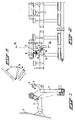
- Fig. 1 shows schematically in side view the pick-up frame with lifting arms of a device according to the invention.
- Fig. 2 is a front view of the pick-up frame, of Fig. 1.
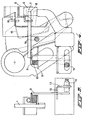
- Fig. 3 is a view on enlarged scale of a detail of Fig. 2.
- Fig. 4 is a view along the line IV-IV in Fig. 2 of the detail of Fig. 3, on the same enlarged scale.
- Fig. 5 shows the various positions of the lifting arms shown in Fig. 1.
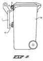
- Fig. 6 shows a container placed on the pick-up frame provided with a container lock comprising a suction cup.
- the device for emptying containers comprises, as shown in Figs. 1 and 2, a pick-up frame 1 and lifting arms 2 which are carried by a vehicle 3.
- the device is provided with a safety mechanism which comprises two parts, a first part 4 which operates when a container edge 5 does not grip properly on a pick-up element in the form of a comb 6, and a second part which operates when the container edge locking mechanism is not closed properly.
- the first part 4 is situated, as Fig. 2 shows, in the second tooth from the left on the comb 6, but can be fitted, depending on the type of pick-up frame and container to be handled, at any point on the comb 6.
- the container edge 5 with the comb 6 is also shown in Fig. 4.
- the other end of the pin 8 is fixed to a switch arm 9.
- a bearing plate 11 is welded to the frame 1.
- the switch arm 9 is detachably connected to the bearing plate 11 by means of a round resilient rubber element 10, having a threaded end at both sides.
- a guide 12 for the switch arm 9 On the frame is also mounted a guide 12 for the switch arm 9 and a mounting plate 13, on which a limit switch 14, which is a part of the control system for the lifting arms 2 and the pick-up frame 1, is adjustably fitted.
- the switch arm 9 can interact with the limit swich 14.
- the lifting movement can be divided into three parts A, B and C (see Fig. 5):
- the limit switch 14 is not activated.
- the switch arm 9 will start to rotate clockwise about the round resilient rubber element 10 (to the situation shown by dashed lines), thereby coming into the switch field of the limit switch 14, as a result of which the latter will switch, during part B of the lifting movement, and the lifting movement will be continued.
- the limit switch 14 will not switch into part B of the lifting movement, as a result of which the lifting movement will be interrupted and will pass into a slow lowering movement. This is done for safety.
- control system is designed in such a way that, if the pin 8 for some reason (e.g. jamming) remains pressed down after a container has been removed from the pick-up frame 1, the following lifting movement cannot be started.
- the advantage of this safety mechanism is the operating reliability and the low sensitivity to soiling.
- the first part of the safety mechanism can also be used for the recognition of certain types of containers, in order to influence the control of the device for emptying containers.
- the second part of the safety mechanism is, as mentioned, operative when the container edge locking mechanism is not closed properly.
- a part of the container edge 5 is still projecting above the comb 6.
- a locking element 15 for the container edge locking which is here made up of an arm which is hingedly connected to the pick-up frame 1 and is provided with a flat part for locking the pick-up edge 5 of the container on the pick-up element 6 of the pick-up frame 1, cannot close properly. Said element 15 comes up against the container edge 5, instead of extending above the container edge.
- a limit switch 16 which becomes active shortly after the start (time settable) of the container edge locking. If the locking element 15 for the container edge is not fully closed after the above-mentioned setting time (see position shown by dashed lines in Fig. 4), the arm of the locking element is still situated in the switch field of the limit switch 16. This will cause the lifting movement to stop and switch over to the slow lowering movement.
- the second part of the safety mechanism which includes the locking element 15 and the limit swich 16 is also effective during the last part of the lifting tipping movement, as will be explained below.
- a device for emptying containers is often provided with a mechanism for locking a container to the pick-up frame during the tipping movement.
- a container locking mechanism may comprise (see Fig. 6) a vacuum operated suction cup 17 which can attach itself firmly to the side wall of a container 18. If this mechanism does not function properly, for example, due to a defect in the vacuum system connected to the suction cup 17 or a damaged suction cup of a damaged container, there is a risk that a container 18 placed on the pick-up frame 1 will start tipping relative to the pick-up frame 1 during the tipping movement of the pick-up frame, and particularly at the end thereof. This may cause the container to become loose from the comb 6 and to fall down.
- the tipping movement of the container 18 relative to the pick-up frame 1 will cause the locking element 15 to rotate relative to the pick-up frame 1.
- the arm of the locking element 15 will then operate the limit swich 16.
- the control system for the drive means will then cause the automatic further movement of the lifting arms 2 and the pick-up frame 1 to stop.
- a reset knob By manually operating a reset knob the pick-up frame 1 with container 18 can be tipped back and lowered at low speed.
Abstract
Description
- The invention relates to a device according to the preamble of
claim 1. - A device of such type is described in, for example, international patent specification WO 89/03794. In said device the sensing element and the first switch are part of a safety system for the drive means of the lifting arms and the pick-up frame. With the sensing element is checked whether the pick-up edge of the container is grasped by the pick-up element in the right way. If this is not the case the container is prevented from being lifted automatically by the lifting arms.
- A disadvantage of the known device is that it has no provisions to guarantee a safe and reliable locking of the pick-up edge of the container on the pick-up frame during lifting and tipping of a container.
- The object of the invention is to remove this disadvantage.
- This object is attained with a device according to the preamble of
claim 1 which is characterized by the features of the characterizing part ofclaim 1. - A device for emptying containers designed in this way comprises a safety mechanism which has two parts, a first part which becomes operative as soon as it is clear that the pick-up edge of a container has not been placed in the envisaged way over the pick-up element of the pick-up frame, and a second part which becomes operative when for one reason or another the locking of the container edge on the pick-up element has not been fully achieved or becomes ineffective.
- Further features and advantages of the invention will be explained below with reference to the drawing.
- Fig. 1 shows schematically in side view the pick-up frame with lifting arms of a device according to the invention.
- Fig. 2 is a front view of the pick-up frame, of Fig. 1.
- Fig. 3 is a view on enlarged scale of a detail of Fig. 2.
- Fig. 4 is a view along the line IV-IV in Fig. 2 of the detail of Fig. 3, on the same enlarged scale.
- Fig. 5 shows the various positions of the lifting arms shown in Fig. 1.
- Fig. 6 shows a container placed on the pick-up frame provided with a container lock comprising a suction cup.
- The device for emptying containers, in particular refuse containers, according to the invention comprises, as shown in Figs. 1 and 2, a pick-
up frame 1 and liftingarms 2 which are carried by a vehicle 3. The device is provided with a safety mechanism which comprises two parts, afirst part 4 which operates when acontainer edge 5 does not grip properly on a pick-up element in the form of acomb 6, and a second part which operates when the container edge locking mechanism is not closed properly. - The
first part 4 is situated, as Fig. 2 shows, in the second tooth from the left on thecomb 6, but can be fitted, depending on the type of pick-up frame and container to be handled, at any point on thecomb 6. Thecontainer edge 5 with thecomb 6 is also shown in Fig. 4. Aslit 7, in which one end of a round pin 8 can move up and down, is made in the tooth. The other end of the pin 8 is fixed to aswitch arm 9. Abearing plate 11 is welded to theframe 1. Theswitch arm 9 is detachably connected to thebearing plate 11 by means of a roundresilient rubber element 10, having a threaded end at both sides. On the frame is also mounted aguide 12 for theswitch arm 9 and amounting plate 13, on which alimit switch 14, which is a part of the control system for the liftingarms 2 and the pick-up frame 1, is adjustably fitted. Theswitch arm 9 can interact with thelimit swich 14. - The lifting movement can be divided into three parts A, B and C (see Fig. 5):
- Part A is the part where the
lifting arm 2 moves from the lowest position (storage position) to the point where the highest container is hanging on thecomb 6 with the wheels just clear of the ground. - Part B is the only part where it is electrically so regulated that the safety mechanism is active. This is a short part of the lifting movement, less than one second.
- Part C is the remainder of the lifting movement.
- As long as the
container edge 5 is not situated over the comb 6 (see the position shown by dashed lines in Fig. 4), thelimit switch 14 is not activated. When the pin 8 is pressed down by thecontainer edge 5, theswitch arm 9 will start to rotate clockwise about the round resilient rubber element 10 (to the situation shown by dashed lines), thereby coming into the switch field of thelimit switch 14, as a result of which the latter will switch, during part B of the lifting movement, and the lifting movement will be continued. - If the pin 8 is not pressed in by the
container edge 5, thelimit switch 14 will not switch into part B of the lifting movement, as a result of which the lifting movement will be interrupted and will pass into a slow lowering movement. This is done for safety. - For additional safety, the control system is designed in such a way that, if the pin 8 for some reason (e.g. jamming) remains pressed down after a container has been removed from the pick-
up frame 1, the following lifting movement cannot be started. The advantage of this safety mechanism is the operating reliability and the low sensitivity to soiling. - The first part of the safety mechanism can also be used for the recognition of certain types of containers, in order to influence the control of the device for emptying containers.
- The second part of the safety mechanism is, as mentioned, operative when the container edge locking mechanism is not closed properly. In the case of used containers with a deformed pick-up edge or in the case of non-standard containers, it can happen that, despite the pin 8 being pressed down, a part of the
container edge 5 is still projecting above thecomb 6. This means that alocking element 15 for the container edge locking which is here made up of an arm which is hingedly connected to the pick-upframe 1 and is provided with a flat part for locking the pick-upedge 5 of the container on the pick-up element 6 of the pick-upframe 1, cannot close properly. Saidelement 15 comes up against thecontainer edge 5, instead of extending above the container edge. - The result of this would be that during the tipping movement the container will come away from the
comb 6 and fall down. - This risk is guarded against by means of a
limit switch 16, which becomes active shortly after the start (time settable) of the container edge locking. If thelocking element 15 for the container edge is not fully closed after the above-mentioned setting time (see position shown by dashed lines in Fig. 4), the arm of the locking element is still situated in the switch field of thelimit switch 16. This will cause the lifting movement to stop and switch over to the slow lowering movement. - The second part of the safety mechanism which includes the
locking element 15 and thelimit swich 16 is also effective during the last part of the lifting tipping movement, as will be explained below. - A device for emptying containers is often provided with a mechanism for locking a container to the pick-up frame during the tipping movement. Such a container locking mechanism may comprise (see Fig. 6) a vacuum operated
suction cup 17 which can attach itself firmly to the side wall of acontainer 18. If this mechanism does not function properly, for example, due to a defect in the vacuum system connected to thesuction cup 17 or a damaged suction cup of a damaged container, there is a risk that acontainer 18 placed on the pick-up frame 1 will start tipping relative to the pick-up frame 1 during the tipping movement of the pick-up frame, and particularly at the end thereof. This may cause the container to become loose from thecomb 6 and to fall down. - However, the tipping movement of the
container 18 relative to the pick-up frame 1 will cause thelocking element 15 to rotate relative to the pick-up frame 1. The arm of thelocking element 15 will then operate thelimit swich 16. The control system for the drive means will then cause the automatic further movement of the liftingarms 2 and the pick-up frame 1 to stop. By manually operating a reset knob the pick-up frame 1 withcontainer 18 can be tipped back and lowered at low speed. - The device for emptying containers according to invention has the following advantages:
- the correct engagement between the comb of the pick-up frame and the pick-up edge of the container is guaranteed;
- the lifting movement cannot be started if the sensing element, which checks the correct engagement between the comb of the pick-up frame and the pick-up edge of the container, remains pressed down, for example, due to a mechanical defect;
- the proper functioning of the container edge locking is checked;
- the automatic lifting and tipping movement of the pick-up frame is stopped when an unwanted continued tipping movement of a container relative to the pick-up frame occurs (for example, due to a defect in the vacuum operated suction cup system).
- the presence of a wrong container is indicated, or a specific container type is recognized.
- a false stroke of the lifting arms is prevented.
Claims (6)
Applications Claiming Priority (2)
| Application Number | Priority Date | Filing Date | Title |
|---|---|---|---|
| NL9002042 | 1990-09-17 | ||
| NL9002042A NL9002042A (en) | 1990-09-17 | 1990-09-17 | SECURITY FOR A CONTAINER LOAD. |
Publications (2)
| Publication Number | Publication Date |
|---|---|
| EP0478049A1 true EP0478049A1 (en) | 1992-04-01 |
| EP0478049B1 EP0478049B1 (en) | 1995-06-07 |
Family
ID=19857691
Family Applications (1)
| Application Number | Title | Priority Date | Filing Date |
|---|---|---|---|
| EP91202357A Expired - Lifetime EP0478049B1 (en) | 1990-09-17 | 1991-09-13 | Device for emptying containers, in particular refuse containers, provided with a safety mechanism |
Country Status (4)
| Country | Link |
|---|---|
| EP (1) | EP0478049B1 (en) |
| DE (1) | DE69110228T2 (en) |
| ES (1) | ES2075334T3 (en) |
| NL (1) | NL9002042A (en) |
Cited By (2)
| Publication number | Priority date | Publication date | Assignee | Title |
|---|---|---|---|---|
| EP0728683A1 (en) * | 1995-02-27 | 1996-08-28 | Max Aicher GmbH Entsorgungstechnik | Device for tilting different types of refuse receptacle from pick-up position to a dump position |
| EP0955252A1 (en) * | 1998-05-06 | 1999-11-10 | Zöller-Kipper GmbH | Emptying device for refuse receptacles with a position recognition and control device |
Citations (4)
| Publication number | Priority date | Publication date | Assignee | Title |
|---|---|---|---|---|
| DE3517491A1 (en) * | 1985-05-15 | 1986-11-20 | G + S Umwelttechnik GmbH, 7107 Nordheim | Lifting or lifting and tipping device for emptying refuse containers into refuse vehicles |
| WO1989003794A1 (en) * | 1987-10-20 | 1989-05-05 | E.S.D. Entsorgungs-Systeme Für Deutschland Gmbh & | Device for emptying containers, in particular refuse containers |
| DE8906456U1 (en) * | 1989-05-26 | 1989-07-27 | Zoeller-Kipper Gmbh, 6500 Mainz, De | |
| EP0358046B1 (en) * | 1988-09-06 | 1991-11-06 | Zöller-Kipper GmbH | Dumping mechanism for emptying receptacles through the opening of collecting containers, especially for emptying waste receptacles into the container of a waste collection vehicle |
-
1990
- 1990-09-17 NL NL9002042A patent/NL9002042A/en not_active Application Discontinuation
-
1991
- 1991-09-13 DE DE69110228T patent/DE69110228T2/en not_active Expired - Fee Related
- 1991-09-13 ES ES91202357T patent/ES2075334T3/en not_active Expired - Lifetime
- 1991-09-13 EP EP91202357A patent/EP0478049B1/en not_active Expired - Lifetime
Patent Citations (4)
| Publication number | Priority date | Publication date | Assignee | Title |
|---|---|---|---|---|
| DE3517491A1 (en) * | 1985-05-15 | 1986-11-20 | G + S Umwelttechnik GmbH, 7107 Nordheim | Lifting or lifting and tipping device for emptying refuse containers into refuse vehicles |
| WO1989003794A1 (en) * | 1987-10-20 | 1989-05-05 | E.S.D. Entsorgungs-Systeme Für Deutschland Gmbh & | Device for emptying containers, in particular refuse containers |
| EP0358046B1 (en) * | 1988-09-06 | 1991-11-06 | Zöller-Kipper GmbH | Dumping mechanism for emptying receptacles through the opening of collecting containers, especially for emptying waste receptacles into the container of a waste collection vehicle |
| DE8906456U1 (en) * | 1989-05-26 | 1989-07-27 | Zoeller-Kipper Gmbh, 6500 Mainz, De |
Cited By (2)
| Publication number | Priority date | Publication date | Assignee | Title |
|---|---|---|---|---|
| EP0728683A1 (en) * | 1995-02-27 | 1996-08-28 | Max Aicher GmbH Entsorgungstechnik | Device for tilting different types of refuse receptacle from pick-up position to a dump position |
| EP0955252A1 (en) * | 1998-05-06 | 1999-11-10 | Zöller-Kipper GmbH | Emptying device for refuse receptacles with a position recognition and control device |
Also Published As
| Publication number | Publication date |
|---|---|
| ES2075334T3 (en) | 1995-10-01 |
| NL9002042A (en) | 1992-04-16 |
| DE69110228D1 (en) | 1995-07-13 |
| EP0478049B1 (en) | 1995-06-07 |
| DE69110228T2 (en) | 1996-02-08 |
Similar Documents
| Publication | Publication Date | Title |
|---|---|---|
| US5484254A (en) | Cup stacking apparatus | |
| EP1674411A1 (en) | Refuse collection vehicle | |
| WO2001030218A1 (en) | Cartridge ejection device | |
| GB2101097A (en) | A materials-handling device | |
| US4424740A (en) | Compactor safety interlock mechanism | |
| CZ149790A3 (en) | Safety switching device for lifting gear with tilting or a tipping gear | |
| US4248276A (en) | Ice dispenser with anti-jamming means | |
| EP0478049A1 (en) | Device for emptying containers, in particular refuse containers, provided with a safety mechanism | |
| US4823535A (en) | Device for unloading X-ray film cassettes | |
| EP1243683A2 (en) | Method and apparatus for automatic pick up of hosiery articles from a container | |
| KR100228232B1 (en) | Equipment for emptying containers | |
| US5303912A (en) | Device for detecting double sheet films | |
| EP0873955B1 (en) | Paper handling apparatus | |
| EP1300346B1 (en) | Device for safely gripping of rubbish-collecting bins | |
| EP4269279A1 (en) | Device for emptying garbage bins into a collecting container of a garbage truck | |
| EP0962401A1 (en) | Loading device for a refuse collection device provided with safety means | |
| EP0413400A1 (en) | Transport vehicle with a container unloading device | |
| WO2004083077A1 (en) | Lifting mechanism for lifting a receptacle | |
| JP3950658B2 (en) | Opening system and opening method | |
| CA1178234A (en) | Retort crate loader and unloader | |
| EP4001174A1 (en) | Guide flap system for a refuse collection vehicle | |
| NL1007748C2 (en) | Rubbish collection vehicle for emptying dustbins | |
| NL1010587C1 (en) | Loading device for refuse collection device | |
| RU2789310C1 (en) | Waste disposal device | |
| JPH0338162Y2 (en) |
Legal Events
| Date | Code | Title | Description |
|---|---|---|---|
| PUAI | Public reference made under article 153(3) epc to a published international application that has entered the european phase |
Free format text: ORIGINAL CODE: 0009012 |
|
| AK | Designated contracting states |
Kind code of ref document: A1 Designated state(s): DE ES FR GB NL |
|
| 17P | Request for examination filed |
Effective date: 19920825 |
|
| 17Q | First examination report despatched |
Effective date: 19930609 |
|
| GRAA | (expected) grant |
Free format text: ORIGINAL CODE: 0009210 |
|
| AK | Designated contracting states |
Kind code of ref document: B1 Designated state(s): DE ES FR GB NL |
|
| ET | Fr: translation filed | ||
| REF | Corresponds to: |
Ref document number: 69110228 Country of ref document: DE Date of ref document: 19950713 |
|
| REG | Reference to a national code |
Ref country code: ES Ref legal event code: FG2A Ref document number: 2075334 Country of ref document: ES Kind code of ref document: T3 |
|
| PLBE | No opposition filed within time limit |
Free format text: ORIGINAL CODE: 0009261 |
|
| STAA | Information on the status of an ep patent application or granted ep patent |
Free format text: STATUS: NO OPPOSITION FILED WITHIN TIME LIMIT |
|
| 26N | No opposition filed | ||
| PGFP | Annual fee paid to national office [announced via postgrant information from national office to epo] |
Ref country code: DE Payment date: 20010920 Year of fee payment: 11 |
|
| PGFP | Annual fee paid to national office [announced via postgrant information from national office to epo] |
Ref country code: FR Payment date: 20010921 Year of fee payment: 11 |
|
| PGFP | Annual fee paid to national office [announced via postgrant information from national office to epo] |
Ref country code: GB Payment date: 20010924 Year of fee payment: 11 Ref country code: ES Payment date: 20010924 Year of fee payment: 11 |
|
| PGFP | Annual fee paid to national office [announced via postgrant information from national office to epo] |
Ref country code: NL Payment date: 20010930 Year of fee payment: 11 |
|
| REG | Reference to a national code |
Ref country code: GB Ref legal event code: IF02 |
|
| PG25 | Lapsed in a contracting state [announced via postgrant information from national office to epo] |
Ref country code: GB Free format text: LAPSE BECAUSE OF NON-PAYMENT OF DUE FEES Effective date: 20020913 |
|
| PG25 | Lapsed in a contracting state [announced via postgrant information from national office to epo] |
Ref country code: ES Free format text: LAPSE BECAUSE OF NON-PAYMENT OF DUE FEES Effective date: 20020914 |
|
| PG25 | Lapsed in a contracting state [announced via postgrant information from national office to epo] |
Ref country code: NL Free format text: LAPSE BECAUSE OF NON-PAYMENT OF DUE FEES Effective date: 20030401 Ref country code: DE Free format text: LAPSE BECAUSE OF NON-PAYMENT OF DUE FEES Effective date: 20030401 |
|
| GBPC | Gb: european patent ceased through non-payment of renewal fee |
Effective date: 20020913 |
|
| PG25 | Lapsed in a contracting state [announced via postgrant information from national office to epo] |
Ref country code: FR Free format text: LAPSE BECAUSE OF NON-PAYMENT OF DUE FEES Effective date: 20030603 |
|
| REG | Reference to a national code |
Ref country code: FR Ref legal event code: ST |
|
| REG | Reference to a national code |
Ref country code: ES Ref legal event code: FD2A Effective date: 20031011 |