EP0477924B1 - Turbo vacuum pump - Google Patents
Turbo vacuum pump Download PDFInfo
- Publication number
- EP0477924B1 EP0477924B1 EP91116371A EP91116371A EP0477924B1 EP 0477924 B1 EP0477924 B1 EP 0477924B1 EP 91116371 A EP91116371 A EP 91116371A EP 91116371 A EP91116371 A EP 91116371A EP 0477924 B1 EP0477924 B1 EP 0477924B1
- Authority
- EP
- European Patent Office
- Prior art keywords
- pump
- vacuum pump
- stage
- turbo vacuum
- rotor
- Prior art date
- Legal status (The legal status is an assumption and is not a legal conclusion. Google has not performed a legal analysis and makes no representation as to the accuracy of the status listed.)
- Expired - Lifetime
Links
Images


Classifications
-
- F—MECHANICAL ENGINEERING; LIGHTING; HEATING; WEAPONS; BLASTING
- F04—POSITIVE - DISPLACEMENT MACHINES FOR LIQUIDS; PUMPS FOR LIQUIDS OR ELASTIC FLUIDS
- F04D—NON-POSITIVE-DISPLACEMENT PUMPS
- F04D29/00—Details, component parts, or accessories
- F04D29/05—Shafts or bearings, or assemblies thereof, specially adapted for elastic fluid pumps
- F04D29/056—Bearings
- F04D29/057—Bearings hydrostatic; hydrodynamic
-
- F—MECHANICAL ENGINEERING; LIGHTING; HEATING; WEAPONS; BLASTING
- F04—POSITIVE - DISPLACEMENT MACHINES FOR LIQUIDS; PUMPS FOR LIQUIDS OR ELASTIC FLUIDS
- F04D—NON-POSITIVE-DISPLACEMENT PUMPS
- F04D17/00—Radial-flow pumps, e.g. centrifugal pumps; Helico-centrifugal pumps
- F04D17/08—Centrifugal pumps
- F04D17/16—Centrifugal pumps for displacing without appreciable compression
- F04D17/168—Pumps specially adapted to produce a vacuum
-
- F—MECHANICAL ENGINEERING; LIGHTING; HEATING; WEAPONS; BLASTING
- F04—POSITIVE - DISPLACEMENT MACHINES FOR LIQUIDS; PUMPS FOR LIQUIDS OR ELASTIC FLUIDS
- F04D—NON-POSITIVE-DISPLACEMENT PUMPS
- F04D19/00—Axial-flow pumps
- F04D19/02—Multi-stage pumps
- F04D19/04—Multi-stage pumps specially adapted to the production of a high vacuum, e.g. molecular pumps
-
- F—MECHANICAL ENGINEERING; LIGHTING; HEATING; WEAPONS; BLASTING
- F04—POSITIVE - DISPLACEMENT MACHINES FOR LIQUIDS; PUMPS FOR LIQUIDS OR ELASTIC FLUIDS
- F04D—NON-POSITIVE-DISPLACEMENT PUMPS
- F04D23/00—Other rotary non-positive-displacement pumps
- F04D23/008—Regenerative pumps
-
- F—MECHANICAL ENGINEERING; LIGHTING; HEATING; WEAPONS; BLASTING
- F04—POSITIVE - DISPLACEMENT MACHINES FOR LIQUIDS; PUMPS FOR LIQUIDS OR ELASTIC FLUIDS
- F04D—NON-POSITIVE-DISPLACEMENT PUMPS
- F04D29/00—Details, component parts, or accessories
- F04D29/05—Shafts or bearings, or assemblies thereof, specially adapted for elastic fluid pumps
- F04D29/051—Axial thrust balancing
- F04D29/0513—Axial thrust balancing hydrostatic; hydrodynamic thrust bearings
Definitions
- the present invention relates to a turbo vacuum pump comprising a housing having an inlet port and an outlet port, a cylindrical rotor disposed in the housing and having a stepped peripheral surface and a plurality of blades secured to protruding corners of the steps, a pumping mechanism portion in which a pumping stage is formed by a stator which faces the blades of said rotor across a narrow gap, and in which peripheral pump flow paths are provided in step-like recessions inside the stator, a rotating shaft connected to said rotor and rotatably supported by bearings, and a motor portion for operating said rotor whereby gas drawn in through the inlet port can be discharged into the atmosphere through the outlet port.
- This generic turbo vacuum pump as described in DE-A-3 932 228 is arranged to have an outlet port at an atmospheric pressure and support the rotating shaft of the pump rotor by ball bearings disposed at two positions and lubricated with oil and thus makes it necessary to provide sealing means between the pump part and the driving part so as not to contaminate the vacuum system.
- sealing means a screw seal of the non-contact type or an oil seal of the non-contact type for purging the compressed gas is employed.
- JP-A-2-16389 describes a turbo molecular drag pump which is arranged to dispose a radial hydrodynamic type gas bearing and a thrust hydrodynamic type gas bearing at the lower end of the rotary shaft and form a gas seal above the hydrodynamic type gas bearings to seal the driving part.
- the turbo molecular drag pump cannot perform exhaust function, unless the discharge pressure falls within a pressure range less than 10 ⁇ 2 Torr so that the interior of the pump is kept at a pressure less than the atmospheric pressure (e.g. 10 ⁇ 2 Torr).
- turbo molecular drag pump as employing gas bearings requires a non-contact seal, since the gas bearings cannot serve satisfactorily in this case.
- a centrifugal pump stage and a peripheral pump stage constitute a pumping mechanism portion, and a hydrodynamic type gas bearing supports a rotating shaft.
- a conventional turbo vacuum pump according to JP-A-62-2581186 is equipped with a housing having an inlet port and an outlet port, the housing extending between the inlet port and the outlet port, a rotating shaft rotatably supported with the aid of a bearing in the housing, a centrifugal pump stage and a peripheral pump stage.
- the pump stages of the above two types are disposed one after another in the housing.
- an impeller, a stator plate, another impeller and another stator plate are alternately arranged in the axial direction of the pump. Both of these plates must be divided in half to insert them. Such a structure is complicated, and there is a limit to how small the structure can be made.
- the pump has a vertical axis structure in which lubricating oil is drawn in from an oil tank at the lower end of the pump so as to lubricate the bearing. Owing to this structure, the number of possible directions from which the pump can be installed is limited. Also, because of the use of the oil-lubricating ball bearing, the oil contaminates the inside of a passage in the pump during long-time use thereof, even though this contamination is negligible.
- turbo vacuum pump of the generic kind that is compact in structure and easy to handle.
- turbo vacuum pump of the generic kind in that its bearings consist of a radial gas bearing and a grease-lubricating ball bearing.
- the rotating shaft of the pump rotor is supported by a radial gas bearing and a grease-lubricating ball bearing. More specifically, the load in the radial direction is supported by the radial gas bearing and the grease-lubricating ball bearing and the load in the thrust direction is supported by the grease-lubricating ball bearing.
- the pressure within the pump housing and at the outlet port is the atmospheric pressure so that the gas bearing acts satisfactorily.
- lubricating oil is not used for the driving part at all so that no special seal is necessary.
- the radial gas bearing is a hydrodynamic type gas bearing.
- a means for cooling air is provided in the motor portion.
- a spiral grooved pump stage is disposed on the side of an inhaling opening of a peripheral pump stage.
- the turbo vacuum pump shown in Fig. 1 is equipped with a pumping mechanism portion and an operating portion.
- the pumping mechanism portion is composed of a peripheral pump impeller 30, a stator 31 and a lid 32.
- the operating portion is composed of a rotating shaft 13 and a high-frequency motor 16 provided around the rotating shaft 13.
- the rotating shaft 13 is rotatably supported by a hydrodynamic type radial gas bearing 33 and a grease lubricating ball bearing 38, both bearings being accommodated in a housing 11.
- the peripheral pump impeller 30 is shaped as a cylinder having steps. A plurality of blades 35 are secured to protruding corners of the steps. As shown in Figs. 2a and 2b, the stator 31 faces the impeller 30 across a narrow gap therebetween. Around each corner a partition 37 is provided in a portion of a circumferential direction of a gas passage 36 so as to surround the blades 35 of the impeller 30. An inhaling opening 36A is formed at the forward side of each partition 37, and a discharge opening 36B is formed at the rear side of each partition 37, where the peripheral pump impeller 30 rotates.
- the position of the inhaling opening 36A of a given stage deviates from that of another inhaling opening 36A of the next stage; likewise, the position of the discharge opening 36B of a given stage deviates from that of another discharge opening 36B of the next stage.
- the inhaling opening 36A of a given stage is connected in series to the discharge opening 36B of the preceding stage. In this way, because the peripheral pump impeller 30 faces the stator 31 at each stage, these components can be integrally formed with each other.
- the hydrodynamic type radial gas bearing 33 has grooves (not shown) formed on the surface thereof; The hydrodynamic type radial gas bearing 33 supports, in a non-contact manner, the vibrations and load of the rotating shaft 13 in the radial direction of the shaft 13.
- the grease lubricating ball bearing 38 supports the vibrations and load of the rotating shaft 13 in the thrust direction of the shaft 13. Because of the integral formation of the peripheral pump impeller 30 and the stator 31, it is possible to improve the accuracy with which these two components are machined.
- the use of the hydrodynamic type radial gas bearing 33 increases the diameter and hence the stiffness of the rotating shaft 13, thus resulting in an improvement in vibration characteristics.
- the high-frequency motor 16, integrally formed with the rotating shaft 13, is capable of operating the peripheral pump impeller 30 at a high speed.
- the peripheral pump impeller 30 Since the peripheral pump impeller 30 operates at a high speed, gas sucked in through an inlet port 11A flows into the gas passage 36 through the inhaling opening 36A of the first stage.
- the blades 35 rotating at a high speed provide the gas with speed in the circumferential direction of the impeller 30.
- a centrifugal force discharges the gas between the blades 35 in the radial direction of the impeller 30.
- the gas flows again between the blades 35 while forming a vortex.
- the gas undergoes the above procedure as many times as the number of stages while it is flowing through the gas passage 36 from the inhaling opening 36A to the discharge opening 36B of each stage.
- the gas flows helically through the gas passage 36 while fully gaining energy from the peripheral pump impeller 30. It is then discharged into the atmosphere through an outlet port 11B connected to the discharge opening 36B of the last stage.
- the peripheral pump impeller 30 gains a high compression ratio in such a manner that it provides the gas with kinetic energy, which is converted into static pressure. Therefore, if it is possible to rotate the peripheral pump impeller 30 at a high speed, it is also possible to improve the performance of the pump.
- the shaft power of the turbo vacuum pump is proportional to the third power of the rotating speed and the fifth power of the diameter of the impeller.
- a spiral grooved pump stage 41 is provided in addition to a peripheral pump stage 40, composed of the peripheral pump impeller 30 and the stator 31, shown in Fig. 1.
- the peripheral pump stage 40 provides gas with speed energy to convert it into pressure. A high compression ratio is thereby obtainable.
- the performance of the pump can increase in the pressure zone of a viscous flow, but decreases in the pressure zones of intermediate and molecular flows.
- the ultimate pressure of the vacuum pump is limited to a low vacuum zone.
- the spiral grooves pump stage 41 which operates effectively with the intermediate and molecular flows, is installed on the low pressure side of the peripheral pump stage 40.
- a centrifugal pump stage, an axial pump stage or the like is used as a pump stage operating effectively with the intermediate and molecular flows.
- these stages must have a structure in which a stator is divided in half to insert it, so that it is difficult to maintain the accuracy with which the stages are machined.
- the stages are not suitable for a smaller pump operating at a higher speed.
- the ultimate pressure of the turbo vacuum pump can be made higher.
- a fan 39 is provided in a housing 11 in which a hydrodynamic type radial gas bearing 33 and a grease-lubricating ball bearing 38 are accommodated.
- This embodiment can effectively remove the heat generated by a high-frequency motor 16 and the grease-lubricating ball bearing 38. It is thus possible to decrease the deterioration of the grease and to increase the life of the bearings.
Description
- The present invention relates to a turbo vacuum pump comprising a housing having an inlet port and an outlet port, a cylindrical rotor disposed in the housing and having a stepped peripheral surface and a plurality of blades secured to protruding corners of the steps, a pumping mechanism portion in which a pumping stage is formed by a stator which faces the blades of said rotor across a narrow gap, and in which peripheral pump flow paths are provided in step-like recessions inside the stator, a rotating shaft connected to said rotor and rotatably supported by bearings, and a motor portion for operating said rotor whereby gas drawn in through the inlet port can be discharged into the atmosphere through the outlet port.
- This generic turbo vacuum pump as described in DE-A-3 932 228 is arranged to have an outlet port at an atmospheric pressure and support the rotating shaft of the pump rotor by ball bearings disposed at two positions and lubricated with oil and thus makes it necessary to provide sealing means between the pump part and the driving part so as not to contaminate the vacuum system. As sealing means a screw seal of the non-contact type or an oil seal of the non-contact type for purging the compressed gas is employed.
- JP-A-2-16389 describes a turbo molecular drag pump which is arranged to dispose a radial hydrodynamic type gas bearing and a thrust hydrodynamic type gas bearing at the lower end of the rotary shaft and form a gas seal above the hydrodynamic type gas bearings to seal the driving part. The turbo molecular drag pump cannot perform exhaust function, unless the discharge pressure falls within a pressure range less than 10⁻² Torr so that the interior of the pump is kept at a pressure less than the atmospheric pressure (e.g. 10⁻² Torr).
- Accordingly, the turbo molecular drag pump as employing gas bearings requires a non-contact seal, since the gas bearings cannot serve satisfactorily in this case.
- In a turbo vacuum pump disclosed in JP-A-1-187396, a centrifugal pump stage and a peripheral pump stage constitute a pumping mechanism portion, and a hydrodynamic type gas bearing supports a rotating shaft.
- A conventional turbo vacuum pump according to JP-A-62-2581186 is equipped with a housing having an inlet port and an outlet port, the housing extending between the inlet port and the outlet port, a rotating shaft rotatably supported with the aid of a bearing in the housing, a centrifugal pump stage and a peripheral pump stage. The pump stages of the above two types are disposed one after another in the housing. In this turbo vacuum pump an impeller, a stator plate, another impeller and another stator plate are alternately arranged in the axial direction of the pump. Both of these plates must be divided in half to insert them. Such a structure is complicated, and there is a limit to how small the structure can be made. The pump has a vertical axis structure in which lubricating oil is drawn in from an oil tank at the lower end of the pump so as to lubricate the bearing. Owing to this structure, the number of possible directions from which the pump can be installed is limited. Also, because of the use of the oil-lubricating ball bearing, the oil contaminates the inside of a passage in the pump during long-time use thereof, even though this contamination is negligible.
- With a turbo vacuum pump as disclosed in JP-A-1-267392 pressure in an outlet port thereof is made equal to the atmospheric pressure so as to discharge gas, and a magnetic bearing, requiring no lubricating oil, is used as the bearing of the pump. Thus no contamination caused by oil occurs since lubricating oil is not used. The magnetic bearing, however, requires a large number of very expensive parts, including a control unit. Because the pump has a complicated structure, it is difficult to reduce the size thereof.
- It is the object of the invention to provide a turbo vacuum pump of the generic kind that is compact in structure and easy to handle.
- This object is achieved with the turbo vacuum pump of the generic kind in that its bearings consist of a radial gas bearing and a grease-lubricating ball bearing.
- In the turbo vacuum pump of the present invention the rotating shaft of the pump rotor is supported by a radial gas bearing and a grease-lubricating ball bearing. More specifically, the load in the radial direction is supported by the radial gas bearing and the grease-lubricating ball bearing and the load in the thrust direction is supported by the grease-lubricating ball bearing. The pressure within the pump housing and at the outlet port is the atmospheric pressure so that the gas bearing acts satisfactorily. In addition, lubricating oil is not used for the driving part at all so that no special seal is necessary.
- Advantageously, the radial gas bearing is a hydrodynamic type gas bearing.
- Conveniently, a means for cooling air is provided in the motor portion.
- Preferably, a spiral grooved pump stage is disposed on the side of an inhaling opening of a peripheral pump stage.
- Embodiments of the invention are described referring to the drawings in which
- Fig. 1
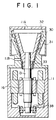
- is a vertical cross-sectional view showing a first embodiment of a turbo vacuum pump,
- Fig. 2a
- is an enlarged vertical cross-sectional view showing a portion around the blades of a peripheral pump impeller illustrated in Fig. 1,
- Fig. 2b
- is an enlarged horizontal cross-sectional view taken along line A-A of Fig. 2a,
- Fig. 3
- is a vertical cross-sectional view showing a second embodiment of a turbo vacuum pump, and
- Fig. 4
- is a vertical cross-sectional view showing a third embodiment of a turbo vacuum pump.
- The turbo vacuum pump shown in Fig. 1 is equipped with a pumping mechanism portion and an operating portion. The pumping mechanism portion is composed of a
peripheral pump impeller 30, astator 31 and alid 32. The operating portion is composed of a rotatingshaft 13 and a high-frequency motor 16 provided around the rotatingshaft 13. The rotatingshaft 13 is rotatably supported by a hydrodynamic type radial gas bearing 33 and a grease lubricating ball bearing 38, both bearings being accommodated in a housing 11. - The
peripheral pump impeller 30 is shaped as a cylinder having steps. A plurality ofblades 35 are secured to protruding corners of the steps. As shown in Figs. 2a and 2b, thestator 31 faces theimpeller 30 across a narrow gap therebetween. Around each corner apartition 37 is provided in a portion of a circumferential direction of agas passage 36 so as to surround theblades 35 of theimpeller 30. Aninhaling opening 36A is formed at the forward side of eachpartition 37, and adischarge opening 36B is formed at the rear side of eachpartition 37, where theperipheral pump impeller 30 rotates. The position of the inhaling opening 36A of a given stage deviates from that of another inhaling opening 36A of the next stage; likewise, the position of the discharge opening 36B of a given stage deviates from that of another discharge opening 36B of the next stage. The inhaling opening 36A of a given stage is connected in series to the discharge opening 36B of the preceding stage. In this way, because theperipheral pump impeller 30 faces thestator 31 at each stage, these components can be integrally formed with each other. The hydrodynamic type radial gas bearing 33 has grooves (not shown) formed on the surface thereof;
The hydrodynamic type radial gas bearing 33 supports, in a non-contact manner, the vibrations and load of the rotatingshaft 13 in the radial direction of theshaft 13. The grease lubricating ball bearing 38 supports the vibrations and load of the rotatingshaft 13 in the thrust direction of theshaft 13. Because of the integral formation of theperipheral pump impeller 30 and thestator 31, it is possible to improve the accuracy with which these two components are machined. The use of the hydrodynamic type radial gas bearing 33 increases the diameter and hence the stiffness of the rotatingshaft 13, thus resulting in an improvement in vibration characteristics. The high-frequency motor 16, integrally formed with the rotatingshaft 13, is capable of operating theperipheral pump impeller 30 at a high speed. - Since the
peripheral pump impeller 30 operates at a high speed, gas sucked in through an inlet port 11A flows into thegas passage 36 through the inhaling opening 36A of the first stage. When the gas flows to theblades 35 of theimpeller 30, theblades 35 rotating at a high speed provide the gas with speed in the circumferential direction of theimpeller 30. A centrifugal force discharges the gas between theblades 35 in the radial direction of theimpeller 30. After the speed of the gas decreases at thegas passage 36 and pressure is recovered, the gas flows again between theblades 35 while forming a vortex. The gas undergoes the above procedure as many times as the number of stages while it is flowing through thegas passage 36 from the inhalingopening 36A to thedischarge opening 36B of each stage. The gas flows helically through thegas passage 36 while fully gaining energy from theperipheral pump impeller 30. It is then discharged into the atmosphere through an outlet port 11B connected to thedischarge opening 36B of the last stage. - As described above, the
peripheral pump impeller 30 gains a high compression ratio in such a manner that it provides the gas with kinetic energy, which is converted into static pressure. Therefore, if it is possible to rotate theperipheral pump impeller 30 at a high speed, it is also possible to improve the performance of the pump. The shaft power of the turbo vacuum pump is proportional to the third power of the rotating speed and the fifth power of the diameter of the impeller. Thus when the peripheral pump impeller is made compact to rotate at a higher speed, the shaft power can be reduced without modifying the performance of the turbo vacuum pump; the size of the turbo vacuum pump can be reduced; and the high-frequency motor 16 having a smaller capacity can be employed. With the embodiment shown in Fig. 3 a spiral groovedpump stage 41 is provided in addition to aperipheral pump stage 40, composed of theperipheral pump impeller 30 and thestator 31, shown in Fig. 1. As described already, theperipheral pump stage 40 provides gas with speed energy to convert it into pressure. A high compression ratio is thereby obtainable. Thus, the performance of the pump can increase in the pressure zone of a viscous flow, but decreases in the pressure zones of intermediate and molecular flows. The ultimate pressure of the vacuum pump is limited to a low vacuum zone. - In the embodiment shown in Fig. 3, to obtain the ultimate pressure even in the pressure zone of the molecular flow, the spiral grooves pump
stage 41, which operates effectively with the intermediate and molecular flows, is installed on the low pressure side of theperipheral pump stage 40. A centrifugal pump stage, an axial pump stage or the like is used as a pump stage operating effectively with the intermediate and molecular flows. However, these stages must have a structure in which a stator is divided in half to insert it, so that it is difficult to maintain the accuracy with which the stages are machined. Thus the stages are not suitable for a smaller pump operating at a higher speed. In this embodiment, because of theperipheral pump stage 40 and the spiral groovedpump stage 41, the ultimate pressure of the turbo vacuum pump can be made higher. - With the embodiment shown in Fig.4 a
fan 39 is provided in a housing 11 in which a hydrodynamic typeradial gas bearing 33 and a grease-lubricatingball bearing 38 are accommodated. - This embodiment can effectively remove the heat generated by a high-
frequency motor 16 and the grease-lubricatingball bearing 38. It is thus possible to decrease the deterioration of the grease and to increase the life of the bearings.
Claims (4)
- A turbo vacuum pump comprising- a housing (11) having an inlet port (11A) and an outlet port (11B),- a cylindrical rotor (30) disposed in the housing (11) and having a stepped peripheral surface and a plurality of blades (35) secured to protruding corners of the steps,- a pumping mechanism portion in which a pumping stage is formed by a stator (31) which faces the blades (35) of said rotor (30) across a narrow gap, and in which peripheral pump flow paths are provided in step-like recessions inside the stator (31),- a rotary shaft (13) connected to said rotor (30) and rotatably supported by bearings (33, 38) and- a motor portion (16) for operating said rotor (30),- whereby gas drawn in through the inlet port (11A) can be discharged into the atmosphere through the outlet port (11B),characterized in that said bearings consist of a radial gas bearing (33) and a grease-lubricating ball bearing (38).
- A turbo vacuum pump according to Claim 1, wherein the radial gas bearing (33) is a hydrodynamic type gas bearing.
- A turbo vacuum pump according to Claim 1 or 2 wherein a means (39) for cooling air is provided in the motor portion (16).
- A turbo vacuum pump according to one of the Claims 1 to 3, wherein a spiral grooved pump stage (41) is disposed on the side of an inhaling opening (36A) of a peripheral pump stage (40).
Applications Claiming Priority (2)
| Application Number | Priority Date | Filing Date | Title |
|---|---|---|---|
| JP256925/90 | 1990-09-28 | ||
| JP2256925A JP2928615B2 (en) | 1990-09-28 | 1990-09-28 | Turbo vacuum pump |
Publications (2)
| Publication Number | Publication Date |
|---|---|
| EP0477924A1 EP0477924A1 (en) | 1992-04-01 |
| EP0477924B1 true EP0477924B1 (en) | 1995-05-03 |
Family
ID=17299285
Family Applications (1)
| Application Number | Title | Priority Date | Filing Date |
|---|---|---|---|
| EP91116371A Expired - Lifetime EP0477924B1 (en) | 1990-09-28 | 1991-09-25 | Turbo vacuum pump |
Country Status (4)
| Country | Link |
|---|---|
| US (1) | US5451147A (en) |
| EP (1) | EP0477924B1 (en) |
| JP (1) | JP2928615B2 (en) |
| DE (1) | DE69109424T2 (en) |
Families Citing this family (9)
| Publication number | Priority date | Publication date | Assignee | Title |
|---|---|---|---|---|
| DE4438812A1 (en) * | 1994-10-31 | 1996-05-02 | Leybold Ag | Friction vacuum pump with cooling |
| WO1997033070A2 (en) * | 1996-03-05 | 1997-09-12 | Shell Internationale Research Maatschappij B.V. | Downhole flow stimulation in a natural gas well |
| JP3010529B1 (en) * | 1998-08-28 | 2000-02-21 | セイコー精機株式会社 | Vacuum pump and vacuum device |
| DE10048695A1 (en) * | 2000-09-30 | 2002-04-11 | Leybold Vakuum Gmbh | Side channel pump for conveying fluid gas mixtures has pump channel running in a spiral coil round rotor |
| US7682301B2 (en) | 2003-09-18 | 2010-03-23 | Thoratec Corporation | Rotary blood pump |
| CN101932837A (en) | 2006-03-31 | 2010-12-29 | 索罗泰克公司 | Rotary blood pump |
| US10641282B2 (en) * | 2016-12-28 | 2020-05-05 | Nidec Corporation | Fan device and vacuum cleaner including the same |
| JP7463150B2 (en) * | 2020-03-19 | 2024-04-08 | エドワーズ株式会社 | Vacuum pumps and vacuum pump parts |
| WO2023137526A1 (en) * | 2022-01-22 | 2023-07-27 | Nihill Jack | Heat engine |
Family Cites Families (11)
| Publication number | Priority date | Publication date | Assignee | Title |
|---|---|---|---|---|
| DE2138152C3 (en) * | 1971-07-30 | 1974-05-09 | W.C. Heraeus Gmbh, 6450 Hanau | Bearing arrangement for the rotor of a turbo molecular pump |
| BE790969A (en) * | 1971-11-16 | 1973-05-07 | Cit Alcatel | PIVOT FOR ROTARY MOLECULAR PUMPS |
| FR2224009A5 (en) * | 1973-03-30 | 1974-10-25 | Cit Alcatel | |
| DE2359456A1 (en) * | 1973-11-29 | 1975-06-05 | Leybold Heraeus Gmbh & Co Kg | TURBOMOLECULAR VACUUM PUMP WITH GAS BEARED ROTOR |
| US4180370A (en) * | 1975-03-22 | 1979-12-25 | Kernforschungsanlage Julich Gesellschaft Mit Beschrankter Haftung | Turbomolecular pump |
| JPS62153597A (en) * | 1985-12-27 | 1987-07-08 | Hitachi Ltd | Vacuum pump |
| CH672666A5 (en) * | 1986-11-27 | 1989-12-15 | Bbc Brown Boveri & Cie | |
| DE3728154C2 (en) * | 1987-08-24 | 1996-04-18 | Balzers Pfeiffer Gmbh | Multi-stage molecular pump |
| DE3891280T1 (en) * | 1988-03-30 | 1990-04-05 | Vladimir Pavlovic Sergeev | TURBOMOLECULAR VACUUM PUMP |
| FR2634829B1 (en) * | 1988-07-27 | 1990-09-14 | Cit Alcatel | VACUUM PUMP |
| US5020969A (en) * | 1988-09-28 | 1991-06-04 | Hitachi, Ltd. | Turbo vacuum pump |
-
1990
- 1990-09-28 JP JP2256925A patent/JP2928615B2/en not_active Expired - Lifetime
-
1991
- 1991-09-25 DE DE69109424T patent/DE69109424T2/en not_active Expired - Fee Related
- 1991-09-25 EP EP91116371A patent/EP0477924B1/en not_active Expired - Lifetime
- 1991-09-30 US US07/767,666 patent/US5451147A/en not_active Expired - Lifetime
Also Published As
| Publication number | Publication date |
|---|---|
| US5451147A (en) | 1995-09-19 |
| DE69109424D1 (en) | 1995-06-08 |
| JPH04136497A (en) | 1992-05-11 |
| JP2928615B2 (en) | 1999-08-03 |
| DE69109424T2 (en) | 1995-09-07 |
| EP0477924A1 (en) | 1992-04-01 |
Similar Documents
| Publication | Publication Date | Title |
|---|---|---|
| EP0568069B1 (en) | Turbomolecular vacuum pumps | |
| EP3401549B1 (en) | Turbo compressor | |
| US3518021A (en) | Thrust bearing for compressor | |
| KR20000062974A (en) | Turbo-molecular pump | |
| US11306726B2 (en) | Foil bearing assembly and compressor including same | |
| EP0477924B1 (en) | Turbo vacuum pump | |
| US5536148A (en) | Turbo vacuum pump | |
| US6409468B1 (en) | Turbo-molecular pump | |
| EP1039138A2 (en) | Vacuum pump with inverted motor | |
| JP2006509952A (en) | Vacuum pump discharge device | |
| JP2741863B2 (en) | Turbo vacuum pump | |
| US6220824B1 (en) | Self-propelled vacuum pump | |
| CN112983850B (en) | Three-wheel centrifugal compressor | |
| JP4576746B2 (en) | Turbo rotating equipment | |
| US6561755B1 (en) | Turbomolecular pump | |
| US7896625B2 (en) | Vacuum pumping system and method of operating a vacuum pumping arrangement | |
| JPH0431692A (en) | Bearing device for vacuum pump | |
| JP2628351B2 (en) | Compound molecular pump | |
| JPH0631198Y2 (en) | Bearing device for leak-free pump | |
| JPH02264196A (en) | Turbine vacuum pump | |
| JP3045418B2 (en) | Turbo vacuum pump | |
| JPH0278793A (en) | Multistage volute type vacuum pump | |
| JPH05248386A (en) | Thread groove type vacuum pump | |
| JP2525848Y2 (en) | Vacuum pump | |
| JPH07217586A (en) | Turbo vacuum pump |
Legal Events
| Date | Code | Title | Description |
|---|---|---|---|
| PUAI | Public reference made under article 153(3) epc to a published international application that has entered the european phase |
Free format text: ORIGINAL CODE: 0009012 |
|
| 17P | Request for examination filed |
Effective date: 19910925 |
|
| AK | Designated contracting states |
Kind code of ref document: A1 Designated state(s): DE GB |
|
| 17Q | First examination report despatched |
Effective date: 19930927 |
|
| GRAA | (expected) grant |
Free format text: ORIGINAL CODE: 0009210 |
|
| AK | Designated contracting states |
Kind code of ref document: B1 Designated state(s): DE GB |
|
| REF | Corresponds to: |
Ref document number: 69109424 Country of ref document: DE Date of ref document: 19950608 |
|
| PLBE | No opposition filed within time limit |
Free format text: ORIGINAL CODE: 0009261 |
|
| STAA | Information on the status of an ep patent application or granted ep patent |
Free format text: STATUS: NO OPPOSITION FILED WITHIN TIME LIMIT |
|
| 26N | No opposition filed | ||
| REG | Reference to a national code |
Ref country code: GB Ref legal event code: IF02 |
|
| PGFP | Annual fee paid to national office [announced via postgrant information from national office to epo] |
Ref country code: GB Payment date: 20020913 Year of fee payment: 12 |
|
| PGFP | Annual fee paid to national office [announced via postgrant information from national office to epo] |
Ref country code: DE Payment date: 20021128 Year of fee payment: 12 |
|
| PG25 | Lapsed in a contracting state [announced via postgrant information from national office to epo] |
Ref country code: GB Free format text: LAPSE BECAUSE OF NON-PAYMENT OF DUE FEES Effective date: 20030925 |
|
| PG25 | Lapsed in a contracting state [announced via postgrant information from national office to epo] |
Ref country code: DE Free format text: LAPSE BECAUSE OF NON-PAYMENT OF DUE FEES Effective date: 20040401 |
|
| GBPC | Gb: european patent ceased through non-payment of renewal fee |
Effective date: 20030925 |