EP0477751B1 - Roll bending machine - Google Patents
Roll bending machine Download PDFInfo
- Publication number
- EP0477751B1 EP0477751B1 EP91115820A EP91115820A EP0477751B1 EP 0477751 B1 EP0477751 B1 EP 0477751B1 EP 91115820 A EP91115820 A EP 91115820A EP 91115820 A EP91115820 A EP 91115820A EP 0477751 B1 EP0477751 B1 EP 0477751B1
- Authority
- EP
- European Patent Office
- Prior art keywords
- roll
- rolls
- flexure
- bending machine
- slider
- Prior art date
- Legal status (The legal status is an assumption and is not a legal conclusion. Google has not performed a legal analysis and makes no representation as to the accuracy of the status listed.)
- Expired - Lifetime
Links
- 238000013000 roll bending Methods 0.000 title claims abstract description 21
- 238000005452 bending Methods 0.000 claims abstract description 44
- 238000005096 rolling process Methods 0.000 claims abstract description 9
- 238000007493 shaping process Methods 0.000 claims description 10
- 230000000284 resting effect Effects 0.000 claims description 3
- 239000002184 metal Substances 0.000 claims 1
- XEEYBQQBJWHFJM-UHFFFAOYSA-N Iron Chemical compound [Fe] XEEYBQQBJWHFJM-UHFFFAOYSA-N 0.000 abstract description 4
- 229910052742 iron Inorganic materials 0.000 abstract description 2
- 238000010586 diagram Methods 0.000 description 2
- 238000006073 displacement reaction Methods 0.000 description 1
- 230000000694 effects Effects 0.000 description 1
- 238000011156 evaluation Methods 0.000 description 1
- 239000012530 fluid Substances 0.000 description 1
- 238000004519 manufacturing process Methods 0.000 description 1
- 238000012986 modification Methods 0.000 description 1
- 230000004048 modification Effects 0.000 description 1
- 230000010355 oscillation Effects 0.000 description 1
Images


Classifications
-
- B—PERFORMING OPERATIONS; TRANSPORTING
- B21—MECHANICAL METAL-WORKING WITHOUT ESSENTIALLY REMOVING MATERIAL; PUNCHING METAL
- B21D—WORKING OR PROCESSING OF SHEET METAL OR METAL TUBES, RODS OR PROFILES WITHOUT ESSENTIALLY REMOVING MATERIAL; PUNCHING METAL
- B21D5/00—Bending sheet metal along straight lines, e.g. to form simple curves
- B21D5/14—Bending sheet metal along straight lines, e.g. to form simple curves by passing between rollers
Definitions
- the present invention relates to roll bending machines for bending plates according to the preamble of claim 1.
- DE-2,547,965; DE-A-2,334,436; DE-A-1,752,666; DE-A-2,903,990; and DE-A-3,443,851 are representative of known prior art.
- the strictest working limit is represented by the minimum bend radius which can be obtained on the plate which the machine has to bend.
- This limit mainly depends on the diameter of the upper roll of the bending machine as well as on the distance between the axes of the lower rolls which must be predefined at the design stage.
- the plate does in fact have to be rolled around the upper dragging roll in order to be bent into a tubular shape.
- the diameter of the upper roll defines a working limit below which the plate cannot be physically bent.
- the minimum working diameter which can be obtained is generally greater than the diameter of the upper roll by a given coefficient.
- the rolls When designing a bending machine the rolls must likewise be dimensioned with a fully defined diameter which takes into account the loads and stresses which working the plate causes to the rolls themselves.
- rolls of a bending machine must be designed and dimensioned not only to an extent such as to withstand the high stress forces which act during the bending operations, but also in order not to flex excessively.
- the object of the present invention is to provide a roll bending machine suitable for solving the problems mentioned previously; more precisely a main object of the present invention is to provide a roll bending machine by means of which it is possible to reduce the diameter and the distances between the axes and the rolls in order to overcome the working limits found with traditional roll bending machines.
- a further object of the present invention is to provide a roll bending machine, as specified above, which in addition to being able to withstand high forces and stresses, also allows the diameter of the rolls to be reduced to a minimum, maintaining the flexure of the rolls themselves within acceptable limits.
- a still further object of the present invention is to provide a roll bending machine, as related, by means of which it is possible to bend plates with extremely small bend radii, and smaller than those which can be currently obtained with traditionally or standard use bending machines.
- a roll bending machine comprises a structure 10 for supporting four shaping rolls, more precisely an upper roll 11, and three lower rolls, of which a central roll 12 and two lateral rolls 13 and 14 arranged with an appropriate distance between their axes.
- the upper roll 11, also known as to plate dragging roll and, optionally, the lower roll 12, also known as to gripping roll, are suitably connected to hydraulic driving motors 15 and 16 respectively, via gearing down units for dragging and guiding in rotation a plate or iron sheet which has to be bent around the upper roll.
- the lower rolls of the bending machine that is to say the gripping roll 12 and the lateral bending rolls 13 and 14, are movably supported towards the upper roll 11.
- the machine is fitted with all those devices required for its working, as for example the device 17 for opening the upper roll in order to remove the plate after it has been bent, and all the necessary control devices which are not explicitly described or illustrated since they do not form a substantial part of the present invention.
- each roll 11, 12, 13 and 14 of the bending machine has been provided with an anti-flexure support in the form of a beam 18 which extends longitudinally and parallel to the same roll on the rear side which is opposite to the one touching the plate; a set of rolling members 19, for example in the form of support rollers having a small diameter, are positioned between each roll of the bending machine and the anti-flexure support beam related to it.
- the individual rolls 11, 12, 13 and 14 instead of being simply supported at their ends, according to the invention they rest in several points, along their entire length, arranging the support rollers 19 placed apart so as to release all the stresses on the anti-flexure beam 18.
- the number, the position and the dimensions of the support rollers 19 may vary depending on the dimensions of the roll bending machine.
- the anti-flexure support 18 for the roll 13 of the bending machine is in the form of a longitudinal beam which is trapezoidal in shape and suitably stiffened and structured to withstand the forces and stresses transmitted by the roll 13 during the bending of a plate.
- the roll 13 is rotatably supported at its ends by the same anti-flexure beam 18 as well as by two sets of intermediate support rollers 19 arranged symmetrically on the two sides of the longitudinal plane of symmetry of the beam 18 which coincides with the longitudinal axis of the roll 13.
- Each roller 19 for supporting the shaping roll 13 of the bending machine is freely rotatable and it is adjustably supported by means of a slider 20 by which it is also possible to give an indication of the adjusted position.
- the slider 20 is suitably guided inside the anti-flexure beam 18 and is shown in greater detail in figures 3 and 4 of the accompanying draggings.
- each slider 18, for the rolls 19 of the anti-flexure beam comprises a guide block 21 having plane guide surfaces and provided with two lateral forks 22 which project upwards beyond the beam 18 to support the pair of support rollers 19.
- the block 21 is guided on the sides by internal guide surfaces 29 of the beam to slide and be adjusted in height to the required position.
- the block 21, or the entire support 20 for each pair of rollers 19, fully releases the forces and the stresses onto the beam 18, resting on an internal cross member 26 by means of a large threaded stem 23, which on one side is screwed into a threaded hole 24 of the block 21, while on the other it has an annular flange 25 resting against the internal cross member 26 of the anti-flexure beam.
- the stem 23, a short distance from the support flange 25, has a hexagonal head 27 by means of which it can be made to rotate to adjust the position in height of the rolls 19, in relation to the shaping roll 13 of the bending machine, while an indexing ring nut 28 fixed to the block 21 is provided with an appropriate scale which, by means of a similar linear scale on the stem 23 allows evaluation of the displacement and hence of the degree of regulation of the support rollers 19 for the roll 13.
- the perfect planarity and the parallel nature of the guide surfaces of each slider 20, enable the rollers 19 to be maintained in a perfectly symmetrical position in relation to the axis of the roll 13 which is thus supported in an appropriate manner in order to prevent any flexure of its axis.
- the beam 18 has suitable lateral openings 30 through which a tool can be inserted.
- each roll of the bending machine is movable with the relative anti-flexure beam in such a way as to form a unitary system within which the stresses and tensions caused by possible flexures of deformations of the roll are released; in this way all the stresses acting on the rotation bearings of the rolls and the oscillation bearings of the support beam are substantially reduced or eliminated.
- each roll of the bending machine is supported in a rotatory manner directly at the ends of the anti-flexure beam 18 which is in turn rigidly connected, for example welded, to two slides 31 which can move in vertical guideways 32 at the two heads of the machine.
- the roll 12 can be supported in an idle rotatory manner by the beam 18 or, preferably, it can be connected to a driving motor 16 which in turn is movable with the beam 18 or with the respective slide 31.
- the vertical movement of raising and lowering the entire assembly of the roll 12 and of its anti-flexure beam 18 may be obtained in any suitable manner, for example by means of a cam system 33 connected to a hydraulic driving cylinder 34 at each end of the anti-flexure beam 18.
- the rotational movement of the entire assembly of the lateral roll 13, 14 and of the relative anti-flexure beam 18, is also achieved in this case by means of hydraulic cylinders 36, suitably connected to a source of pressurized fluid.
- the two rocking plates 34 of the lateral rolls are connected by means of a connecting rod 37 and a lever 38 to a torsion bar 39 which reacts to ensure this parallel arrangement.
- shaping rolls with a very small diameter in relation to rolls on traditional machines, can be mounted, allows a further advantage which consists in the fact that distances between the axes of the lower rolls are reduced considerably.
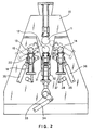
- This is shown, by way of an example, in the diagram in Fig. 5 where the dimensions and the positions of the shaping rolls 11, 12, 13 and 14 of a bending machine according to the invention are compared with corresponding rolls 11′, 12′, 13′ and 14′ of a traditional bending machine. All this leads to the advantage of being able to bend plate having very small bend radii, avoiding damaging and dangerous deformations in the upper rolls of the same bending machine.
Landscapes
- Engineering & Computer Science (AREA)
- Mechanical Engineering (AREA)
- Bending Of Plates, Rods, And Pipes (AREA)
- Rolls And Other Rotary Bodies (AREA)
- Treatment Of Fiber Materials (AREA)
- Machines For Manufacturing Corrugated Board In Mechanical Paper-Making Processes (AREA)
- Reduction Rolling/Reduction Stand/Operation Of Reduction Machine (AREA)
Abstract
Description
- The present invention relates to roll bending machines for bending plates according to the preamble of claim 1.
- DE-2,547,965; DE-A-2,334,436; DE-A-1,752,666; DE-A-2,903,990; and DE-A-3,443,851 are representative of known prior art.
- The above cited documents, particularly DE-A-2,847,965 which constitutes the basis for present claim 1, relate to roll bending machines wherein anti-flexure support means are provided to prevent flexure of the upper dragging roll, respectively of the central lower roll of the machine, and in which rolling members are placed between the anti-flexure supports and the rolls of the machine. None of the cited references, taken alone or in combination, suggests modifications of a four rolls bending machine having the characterising features of the present invention.
- In roll bending machines, the strictest working limit is represented by the minimum bend radius which can be obtained on the plate which the machine has to bend.
- This limit mainly depends on the diameter of the upper roll of the bending machine as well as on the distance between the axes of the lower rolls which must be predefined at the design stage. The plate does in fact have to be rolled around the upper dragging roll in order to be bent into a tubular shape. As a result the diameter of the upper roll defines a working limit below which the plate cannot be physically bent. On the contrary, in view of the "spring back" of the plate, the minimum working diameter which can be obtained is generally greater than the diameter of the upper roll by a given coefficient.
- When designing a bending machine the rolls must likewise be dimensioned with a fully defined diameter which takes into account the loads and stresses which working the plate causes to the rolls themselves. The greater the thickness and the dimensions of the plates to be worked, the higher the stresses and the strains acting on the rolls and, consequently, the greater the resulting diameter of the rolls themselves must be.
- Another element which conditions the diameter of the rolls of a bending machine is represented by the flexure which the same rolls undergo due to the forces which they exert during working. In fact, if the flexure of the rolls is too high, albeit without involving risks for the rolls themselves, the result of working would be of poor quality and unacceptable since the bent plate would be deformed or would lack the required cylindricity since, due to the excessive flexure of the rolls, a bend with the so-called "barrel effect" would be obtained.
- Therefore the rolls of a bending machine must be designed and dimensioned not only to an extent such as to withstand the high stress forces which act during the bending operations, but also in order not to flex excessively.
- The actual lenght of the bending machine affects the flexure of the rolls and hence the diameter of the rolls themselves. Therefore, in bending machines of considerable length, for the purpose of limiting the flexure of the rolls within acceptable values, the diameter has to be increased by introducing further restrictions to working.
- These working limits and restrictions of roll bending machines are accepted unwillingly due to the increasingly felt requirement for bending machines capable of offering the maximum working potential.
- It would therefore be desiderable to have roll bending machines also capable of working plates of considerable length, and with bend radii which are as small as possible.
- The plate bending machines of the type mentioned, currently available, are not able to fulfil these requirements.
- For this reason special expedients or bending machines of another kind have to be used, with considerably high working costs and with results whose quality is at times poor. In fact the only possibility currently allowed, besides that of using machines of another kind, is of using very short bending machines for bending a high number of plates which then have to be welded side by side with high production costs and with technical and aesthetic results which are not always acceptable by users.
- The object of the present invention is to provide a roll bending machine suitable for solving the problems mentioned previously; more precisely a main object of the present invention is to provide a roll bending machine by means of which it is possible to reduce the diameter and the distances between the axes and the rolls in order to overcome the working limits found with traditional roll bending machines.
- A further object of the present invention is to provide a roll bending machine, as specified above, which in addition to being able to withstand high forces and stresses, also allows the diameter of the rolls to be reduced to a minimum, maintaining the flexure of the rolls themselves within acceptable limits.
- A still further object of the present invention is to provide a roll bending machine, as related, by means of which it is possible to bend plates with extremely small bend radii, and smaller than those which can be currently obtained with traditionally or standard use bending machines.
- The above can be achieved by means of a roll bending machine having the characteristics specified in the main claim.
- A preferred embodiment of a roll bending machine according to the present invention, is described hereinunder with reference to the figures in the accompanying drawings, in which:
- Fig. 1
- is a schematic view, in a longitudinal plane, of a roll bending machine according to the invention;
- Fig. 2
- is a cross-sectional view along line 2-2 of Fig. 1 with some parts removed;
- Fig. 3
- is an enlarged detail of a beam for supporting the rolls of Fig. 2;
- Fig. 4
- is a longitudinal sectional view along line 4-4 of Fig. 3;
- Fig. 5
- is a diagram which compares the arrangement and the dimensions of the rolls of a roll bending machine according to the invention, with those of a traditional roll bending machine.
- With reference first to Figures 1 and 2, we will now describe the general characteristics of a roll bending machine, according to the present invention.
- In general a roll bending machine comprises a
structure 10 for supporting four shaping rolls, more precisely anupper roll 11, and three lower rolls, of which acentral roll 12 and twolateral rolls - The
upper roll 11, also known as to plate dragging roll and, optionally, thelower roll 12, also known as to gripping roll, are suitably connected tohydraulic driving motors - As explained hereinunder, the lower rolls of the bending machine, that is to say the
gripping roll 12 and thelateral bending rolls upper roll 11. The machine is fitted with all those devices required for its working, as for example thedevice 17 for opening the upper roll in order to remove the plate after it has been bent, and all the necessary control devices which are not explicitly described or illustrated since they do not form a substantial part of the present invention. - As related previously, for the purpose of maintaining the diameter of the rolls of the bending machine comparatively small, at the same time preventing the rolls from being damaged or from undergoing undesiderable flexures even when they are subjected to considerable forces and stresses, according to the main characteristic of the present invention each
roll beam 18 which extends longitudinally and parallel to the same roll on the rear side which is opposite to the one touching the plate; a set of rollingmembers 19, for example in the form of support rollers having a small diameter, are positioned between each roll of the bending machine and the anti-flexure support beam related to it. In this way, unlike traditional bending machines, the individual rolls 11, 12, 13 and 14, instead of being simply supported at their ends, according to the invention they rest in several points, along their entire length, arranging thesupport rollers 19 placed apart so as to release all the stresses on theanti-flexure beam 18. The number, the position and the dimensions of thesupport rollers 19 may vary depending on the dimensions of the roll bending machine. - Hereinunder we will describe in greater detail a preferred embodiment of an anti-flexure support according to the present invention, referring by way of an example to the
lateral roll 13, without prejudice to the fact that the anti-flexure supports of the remaining rolls have identical or similar characteristics to those described hereinunder. - As shown in figures 2, 3 and 4, the anti-flexure support 18 for the
roll 13 of the bending machine, is in the form of a longitudinal beam which is trapezoidal in shape and suitably stiffened and structured to withstand the forces and stresses transmitted by theroll 13 during the bending of a plate. - More particularly, the
roll 13 is rotatably supported at its ends by the sameanti-flexure beam 18 as well as by two sets ofintermediate support rollers 19 arranged symmetrically on the two sides of the longitudinal plane of symmetry of thebeam 18 which coincides with the longitudinal axis of theroll 13. Eachroller 19 for supporting theshaping roll 13 of the bending machine, is freely rotatable and it is adjustably supported by means of aslider 20 by which it is also possible to give an indication of the adjusted position. Theslider 20 is suitably guided inside theanti-flexure beam 18 and is shown in greater detail in figures 3 and 4 of the accompanying draggings. - More particularly, as shown in the aforementioned figures, each
slider 18, for therolls 19 of the anti-flexure beam, comprises aguide block 21 having plane guide surfaces and provided with twolateral forks 22 which project upwards beyond thebeam 18 to support the pair ofsupport rollers 19. - The
block 21 is guided on the sides byinternal guide surfaces 29 of the beam to slide and be adjusted in height to the required position. Theblock 21, or theentire support 20 for each pair ofrollers 19, fully releases the forces and the stresses onto thebeam 18, resting on aninternal cross member 26 by means of a large threadedstem 23, which on one side is screwed into a threadedhole 24 of theblock 21, while on the other it has anannular flange 25 resting against theinternal cross member 26 of the anti-flexure beam. Thestem 23, a short distance from thesupport flange 25, has ahexagonal head 27 by means of which it can be made to rotate to adjust the position in height of therolls 19, in relation to theshaping roll 13 of the bending machine, while anindexing ring nut 28 fixed to theblock 21 is provided with an appropriate scale which, by means of a similar linear scale on thestem 23 allows evaluation of the displacement and hence of the degree of regulation of thesupport rollers 19 for theroll 13. The perfect planarity and the parallel nature of the guide surfaces of eachslider 20, enable therollers 19 to be maintained in a perfectly symmetrical position in relation to the axis of theroll 13 which is thus supported in an appropriate manner in order to prevent any flexure of its axis. - For the purpose of acting on the threaded
stems 23 of each slider, to regulate variously the position of thesupport rollers 19 at eachslider 20, thebeam 18 has suitablelateral openings 30 through which a tool can be inserted. - In the specific case a particular solution has been shown as regards the means for adjusting the position of the
support rollers 19 for the shaping rolls of the bending machine, nevertheless it is understood that other solutions are possible within the scope of the present invention. - As mentioned initially, the
lower gripping roll 12 and the twolateral bending rolls upper dragging roll 11. Therefore, according to a further characteristic of the present invention, each roll of the bending machine is movable with the relative anti-flexure beam in such a way as to form a unitary system within which the stresses and tensions caused by possible flexures of deformations of the roll are released; in this way all the stresses acting on the rotation bearings of the rolls and the oscillation bearings of the support beam are substantially reduced or eliminated. - More particularly, as shown for example in figures 1 and 2 for the
central gripping roll 12, each roll of the bending machine is supported in a rotatory manner directly at the ends of theanti-flexure beam 18 which is in turn rigidly connected, for example welded, to twoslides 31 which can move invertical guideways 32 at the two heads of the machine. Theroll 12 can be supported in an idle rotatory manner by thebeam 18 or, preferably, it can be connected to a drivingmotor 16 which in turn is movable with thebeam 18 or with therespective slide 31. The vertical movement of raising and lowering the entire assembly of theroll 12 and of itsanti-flexure beam 18 may be obtained in any suitable manner, for example by means of acam system 33 connected to ahydraulic driving cylinder 34 at each end of theanti-flexure beam 18. - In a substantially similar manner, each of the two
lateral bending rolls roll 14, is supported in an idle rotatory manner by the respective anti-flexure beam which in turn is rigidly connected to two end plates 34 (only one is shown in Fig. 2), hinged in 35 to the structure of the machine in order to rotate along an axis parallel to the axis of the same roll, as shown by the dotted line in Figure 2. The rotational movement of the entire assembly of thelateral roll anti-flexure beam 18, is also achieved in this case by means ofhydraulic cylinders 36, suitably connected to a source of pressurized fluid. In order to always ensure a perfectly horizontal and parallel arrangement of each roll, that is to say for the purpose of ensuring an arrangement parallel to the rolls of the bending machine, the tworocking plates 34 of the lateral rolls are connected by means of a connectingrod 37 and alever 38 to atorsion bar 39 which reacts to ensure this parallel arrangement. - From what has been said and shown in the accompanying draggings, it is therefore clear that the provision to each shaping roll of the bending machine of its own anti-flexure beam with sets of support or bucking rollers placed between each shaping roll of the bending machine and the anti-flexure beam itself, enables the diameter of the shaping rolls to be reduced considerably, even on machines of considerable length.
- Furthermore, the fact that shaping rolls with a very small diameter, in relation to rolls on traditional machines, can be mounted, allows a further advantage which consists in the fact that distances between the axes of the lower rolls are reduced considerably. This is shown, by way of an example, in the diagram in Fig. 5 where the dimensions and the positions of the shaping rolls 11, 12, 13 and 14 of a bending machine according to the invention are compared with
corresponding rolls 11′, 12′, 13′ and 14′ of a traditional bending machine. All this leads to the advantage of being able to bend plate having very small bend radii, avoiding damaging and dangerous deformations in the upper rolls of the same bending machine. - It can be understood therefore that what has been said and shown in the accompanying draggings has been given merely by way of an example of the general principles of the invention which is claimed.
Claims (5)
- A roll bending machine for bending metal plates, said machine having upper and lower opposed gripping rolls (11, 12) defining a nip between them, and lateral shaping rolls (13, 14) parallelly arranged on opposite side of said upper and lower rolls (11, 12), wherein said lower roll (12) and said lateral rolls (13, 14) are supported to move towards the upper roll (11) and wherein anti-flexure support means comprising intermediate rolling members are provided for the rolls, characterised in that said anti-flexure support means comprises a support beam (18) for each roll (11, 12, 13, 14) of the machine, said support beam (18) extending parallel to the roll; a set of rolling members (19) mounted for rotation between each roll (11, 12, 13, 14) and respective support beam (18), said rolling members (19) being axially aligned lengthwise the support beam (18) to contact and support said roll (11- 14); and adjustable guide means (21) for individually guiding and indexing adjusted positions of said rolling means (19) in respect to the beam (18) and corresponding roll (11-14) of the machine; and pivotable support plates (34) for mounting either the support beam (18) of each lateral rolls (13, 14) and the relative guide means of the rolling members, for a rocking movement about an axis (35) parallel to and spaced apart from the lower roll of the machine; and an anti-torsion bar (39) connected by articulate levers (37, 38) to the opposite ends of the support beam of each lateral roll to maintain parallelism during rocking movement of said lateral rolls (13, 14).
- A bending machine according to claims 1, characterised in that said rolling members (19) comprise pairs of back rollers which are arranged on opposite sides of a working roll (11, 12, 13, 14) each pair of back rollers (19) movable being provided on a slider (20) inside the anti-flexure beam (18), means (29) for guiding and means (23, 24) for adjusting the position of said slider being provided between said slider and said anti-flexure beam (18).
- A bending machine according to claim 2, characterised in that said guide means comprise plane guide surfaces (21, 29) on said slider (20) respectively inside the anti-flexure beam (18).
- A bending machine according to claim 2, characterised in that said means for adjusting the position of the slider (20) comprise a threaded stem (23) engaging into a threaded hole (24) of the slider (20) respectively resting on an internal cross member (26) of the anti-flexure beam (18), and in that said stem (23) and said slider (20) are provided respectively with indexing means (28).
- A bending machine according to claim 4, characterised in that the anti-flexure beam (18) comprises lateral openings (30) in correspondence of said indexing means (28).
Applications Claiming Priority (2)
| Application Number | Priority Date | Filing Date | Title |
|---|---|---|---|
| IT01472790U IT223460Z2 (en) | 1990-09-28 | 1990-09-28 | BENDING CALENDER WITH 4 SHAPING ROLLERS WITH LONGITUDINAL ANTI-DEFLECTION SUPPORTS AND SEASES OF CONTRAST ROLLERS. |
| IT1472790U | 1990-09-28 |
Publications (2)
| Publication Number | Publication Date |
|---|---|
| EP0477751A1 EP0477751A1 (en) | 1992-04-01 |
| EP0477751B1 true EP0477751B1 (en) | 1994-06-29 |
Family
ID=11145668
Family Applications (1)
| Application Number | Title | Priority Date | Filing Date |
|---|---|---|---|
| EP91115820A Expired - Lifetime EP0477751B1 (en) | 1990-09-28 | 1991-09-18 | Roll bending machine |
Country Status (5)
| Country | Link |
|---|---|
| US (1) | US5218850A (en) |
| EP (1) | EP0477751B1 (en) |
| AT (1) | ATE107877T1 (en) |
| DE (1) | DE69102689T2 (en) |
| IT (1) | IT223460Z2 (en) |
Families Citing this family (13)
| Publication number | Priority date | Publication date | Assignee | Title |
|---|---|---|---|---|
| IT1289355B1 (en) * | 1996-12-18 | 1998-10-02 | Promau Srl | PROCEDURE FOR BENDING SHEETS, AND RELATED CALENDER |
| KR100421818B1 (en) * | 2001-09-11 | 2004-03-11 | 평산에스아이 주식회사 | Bending machine for corrugated steel structural plate |
| FR2876927B1 (en) * | 2004-10-25 | 2008-05-16 | Jammes Ind Sa Sa | BANDING MACHINE FOR SHEETS AND MANUFACTURING LINE INCORPORATING SUCH A MACHINE |
| DE102010041296A1 (en) * | 2010-09-23 | 2012-03-29 | Theodor Gräbener GmbH & Co. KG | Four-roll bending machine and method for bending and rolling sheet metal |
| ITMI20111408A1 (en) * | 2011-07-27 | 2013-01-28 | Promau Srl | APPARATUS AND METHOD FOR THE ELECTRO-HYDRAULIC CONTROL OF PARALLELISM IN A CALENDER FOR METAL MANUFACTURING |
| JP5931485B2 (en) * | 2012-02-14 | 2016-06-08 | 株式会社栗本鐵工所 | Bending roll |
| CN103264074A (en) * | 2013-04-23 | 2013-08-28 | 南京环力重工机械有限公司 | Four-roller plate bending machine and method for rolling circular tubes |
| CN104550348B (en) * | 2015-01-31 | 2016-08-17 | 南通市源泉智能仪表产品有限公司 | The veneer reeling machine that a kind of security performance is high |
| CN106734414A (en) * | 2016-12-05 | 2017-05-31 | 上海振华重工(集团)股份有限公司 | The misalignment correction material drag device of veneer reeling machine |
| US11219933B2 (en) * | 2017-11-10 | 2022-01-11 | Promau S.R.L. | Apparatus and method for support and controlled advancement of a metal sheet in a bending machine for obtaining cylindrical or truncated cone structures |
| CN108655219B (en) * | 2018-05-03 | 2020-08-14 | 蓬莱大金海洋重工有限公司 | Plate material rolling process |
| IT201800006763A1 (en) * | 2018-06-28 | 2019-12-28 | Roller bending machine and method for bending elongated pieces. | |
| CN109158457A (en) * | 2018-09-25 | 2019-01-08 | 广州广源兴科技有限公司 | Bending roll machine |
Family Cites Families (14)
| Publication number | Priority date | Publication date | Assignee | Title |
|---|---|---|---|---|
| US160647A (en) * | 1875-03-09 | Improvement in metal-bending machines | ||
| US1614425A (en) * | 1926-05-22 | 1927-01-11 | American Brass Co | Rolling mill |
| US1787558A (en) * | 1927-11-07 | 1931-01-06 | Tinsman John De Witt | Rolling mill |
| US2877821A (en) * | 1954-08-04 | 1959-03-17 | Bliss E W Co | Upcoiler with rolls independently driven at surface speed of material being coiled |
| US2995171A (en) * | 1955-12-14 | 1961-08-08 | Hausler Christian | Machine for bending metal plates |
| DE1752666C3 (en) * | 1968-06-29 | 1975-09-25 | Wilhelmsburger Maschinenfabrik, Hinrichs & Sohn, 2054 Geesthacht | Sheet metal bending machine |
| DE2334436A1 (en) * | 1973-07-06 | 1975-01-23 | Carl Friedrich Tenge Rietberg | Four-roller sheet metal bending machine - with vertically adjustable upper rolls and two swivelling lateral lower rolls |
| DE2537188C3 (en) * | 1975-08-21 | 1978-05-18 | Bwg Bergwerk- Und Walzwerk-Maschinenbau Gmbh, 4100 Duisburg | Method and device for the production of hot strip with improved quality properties |
| JPS5524761A (en) * | 1978-08-11 | 1980-02-22 | Nippon Kokan Kk <Nkk> | Roll-bending type steel pipe manufacturing equipment |
| DE2847965C2 (en) * | 1978-11-04 | 1980-12-11 | Schaefer Maschbau Wilhelm | Four roll bending machine |
| DE2903990A1 (en) * | 1979-02-02 | 1980-08-07 | Gottlieb Dangel | Bending machine for mfg. gutters or tubes from metal sheet - esp. roof gutters from metal sheet coated with plastic, which is not damaged by bending rolls |
| SU822946A1 (en) * | 1979-05-10 | 1981-04-23 | Славянский Филиал Всесоюзногоордена Ленина Научно-Исследова-Тельского И Проектно-Конструк-Торского Института Металлур-Гического Машиностроения | Apparatus for straightening strip |
| FI74414C (en) * | 1980-08-18 | 1988-02-08 | Sl Tuotanto Oy | ANORDING FOR FRAMSTAELLNING AV ETT METALLROER. |
| CH665572A5 (en) * | 1984-11-30 | 1988-05-31 | Kz Aviatsion Inst Tupoleva | TWO-ROLLER TURNING MACHINE. |
-
1990
- 1990-09-28 IT IT01472790U patent/IT223460Z2/en active IP Right Grant
-
1991
- 1991-09-18 EP EP91115820A patent/EP0477751B1/en not_active Expired - Lifetime
- 1991-09-18 AT AT91115820T patent/ATE107877T1/en not_active IP Right Cessation
- 1991-09-18 DE DE69102689T patent/DE69102689T2/en not_active Expired - Fee Related
- 1991-09-20 US US07/763,239 patent/US5218850A/en not_active Expired - Fee Related
Also Published As
| Publication number | Publication date |
|---|---|
| ATE107877T1 (en) | 1994-07-15 |
| US5218850A (en) | 1993-06-15 |
| IT9014727V0 (en) | 1990-09-28 |
| IT9014727U1 (en) | 1992-03-28 |
| IT223460Z2 (en) | 1995-07-19 |
| EP0477751A1 (en) | 1992-04-01 |
| DE69102689T2 (en) | 1995-01-12 |
| DE69102689D1 (en) | 1994-08-04 |
Similar Documents
| Publication | Publication Date | Title |
|---|---|---|
| EP0477751B1 (en) | Roll bending machine | |
| US4491004A (en) | Apparatus for manufacturing a metal pipe | |
| US3854315A (en) | Variable width strip conditioner | |
| US5680785A (en) | Metal strip planishing installation | |
| JPH04228226A (en) | Forming machine for bending plate into cylindrical shape | |
| JP2650141B2 (en) | Metal strip straightening equipment | |
| EP0416880B1 (en) | Rolling mill and rolling method | |
| CA1147635A (en) | Forming leveler | |
| EP0476905B1 (en) | Shape control in a strip rolling mill of cluster type | |
| EP0463039B1 (en) | Apparatus for forming a pipe from a sheet metal plate | |
| US4719781A (en) | Device for straightening metal wires by means of a plurality of rollers | |
| US3543555A (en) | Form changing device for continuous casting | |
| GB2028201A (en) | Axial adjustment device for tapered intermediate rolls in a cluster mill stand | |
| KR910005829B1 (en) | Six-high roll stand with braced and removable working rolls | |
| EP1038602A1 (en) | Method and device for straightening profiles | |
| US6571592B1 (en) | Rolling mill with roll deflection bi-dimensionally controlled | |
| US4823582A (en) | Device for planing a sheet metal strip under tension | |
| US4539833A (en) | Rolling mill with flatness control facility | |
| CN211839630U (en) | Different roll spacing sheet material leveler | |
| WO1999011397A1 (en) | A rolling mill with roll deflection bi-dimensionally controlled | |
| DE2362805B2 (en) | Transducer arrangement | |
| EP1020237B1 (en) | A mill for rolling strips or plates | |
| CN1163316C (en) | A rolling mill with roll deflection bi-dimensionally controller | |
| US4433716A (en) | Roller apron for the withdrawal and/or straightening region of a continuous casting installation for strands | |
| JPH0810430Y2 (en) | Rolling mill |
Legal Events
| Date | Code | Title | Description |
|---|---|---|---|
| PUAI | Public reference made under article 153(3) epc to a published international application that has entered the european phase |
Free format text: ORIGINAL CODE: 0009012 |
|
| AK | Designated contracting states |
Kind code of ref document: A1 Designated state(s): AT BE CH DE DK ES FR GB GR IT LI NL SE |
|
| 17P | Request for examination filed |
Effective date: 19920918 |
|
| 17Q | First examination report despatched |
Effective date: 19930525 |
|
| GRAA | (expected) grant |
Free format text: ORIGINAL CODE: 0009210 |
|
| AK | Designated contracting states |
Kind code of ref document: B1 Designated state(s): AT BE CH DE DK ES FR GB GR IT LI NL SE |
|
| PG25 | Lapsed in a contracting state [announced via postgrant information from national office to epo] |
Ref country code: NL Effective date: 19940629 Ref country code: GR Free format text: LAPSE BECAUSE OF FAILURE TO SUBMIT A TRANSLATION OF THE DESCRIPTION OR TO PAY THE FEE WITHIN THE PRESCRIBED TIME-LIMIT Effective date: 19940629 Ref country code: ES Free format text: THE PATENT HAS BEEN ANNULLED BY A DECISION OF A NATIONAL AUTHORITY Effective date: 19940629 Ref country code: DK Effective date: 19940629 Ref country code: BE Effective date: 19940629 Ref country code: AT Effective date: 19940629 |
|
| REF | Corresponds to: |
Ref document number: 107877 Country of ref document: AT Date of ref document: 19940715 Kind code of ref document: T |
|
| ITF | It: translation for a ep patent filed | ||
| ET | Fr: translation filed | ||
| REF | Corresponds to: |
Ref document number: 69102689 Country of ref document: DE Date of ref document: 19940804 |
|
| PG25 | Lapsed in a contracting state [announced via postgrant information from national office to epo] |
Ref country code: SE Effective date: 19940929 |
|
| PGFP | Annual fee paid to national office [announced via postgrant information from national office to epo] |
Ref country code: NL Payment date: 19940930 Year of fee payment: 4 |
|
| NLV1 | Nl: lapsed or annulled due to failure to fulfill the requirements of art. 29p and 29m of the patents act | ||
| PLBE | No opposition filed within time limit |
Free format text: ORIGINAL CODE: 0009261 |
|
| STAA | Information on the status of an ep patent application or granted ep patent |
Free format text: STATUS: NO OPPOSITION FILED WITHIN TIME LIMIT |
|
| 26N | No opposition filed | ||
| PGFP | Annual fee paid to national office [announced via postgrant information from national office to epo] |
Ref country code: FR Payment date: 20000726 Year of fee payment: 10 |
|
| PGFP | Annual fee paid to national office [announced via postgrant information from national office to epo] |
Ref country code: GB Payment date: 20000911 Year of fee payment: 10 Ref country code: CH Payment date: 20000911 Year of fee payment: 10 |
|
| PGFP | Annual fee paid to national office [announced via postgrant information from national office to epo] |
Ref country code: DE Payment date: 20001002 Year of fee payment: 10 |
|
| PG25 | Lapsed in a contracting state [announced via postgrant information from national office to epo] |
Ref country code: GB Free format text: LAPSE BECAUSE OF NON-PAYMENT OF DUE FEES Effective date: 20010918 |
|
| PG25 | Lapsed in a contracting state [announced via postgrant information from national office to epo] |
Ref country code: LI Free format text: LAPSE BECAUSE OF NON-PAYMENT OF DUE FEES Effective date: 20010930 Ref country code: CH Free format text: LAPSE BECAUSE OF NON-PAYMENT OF DUE FEES Effective date: 20010930 |
|
| REG | Reference to a national code |
Ref country code: GB Ref legal event code: IF02 |
|
| PG25 | Lapsed in a contracting state [announced via postgrant information from national office to epo] |
Ref country code: DE Free format text: LAPSE BECAUSE OF NON-PAYMENT OF DUE FEES Effective date: 20020501 |
|
| GBPC | Gb: european patent ceased through non-payment of renewal fee |
Effective date: 20010918 |
|
| REG | Reference to a national code |
Ref country code: CH Ref legal event code: PL |
|
| PG25 | Lapsed in a contracting state [announced via postgrant information from national office to epo] |
Ref country code: FR Free format text: LAPSE BECAUSE OF NON-PAYMENT OF DUE FEES Effective date: 20020531 |
|
| REG | Reference to a national code |
Ref country code: FR Ref legal event code: ST |
|
| PG25 | Lapsed in a contracting state [announced via postgrant information from national office to epo] |
Ref country code: IT Free format text: LAPSE BECAUSE OF NON-PAYMENT OF DUE FEES Effective date: 20050918 |