EP0477610A1 - Multipolar pluggable coupling parts for electrical conductors - Google Patents
Multipolar pluggable coupling parts for electrical conductors Download PDFInfo
- Publication number
- EP0477610A1 EP0477610A1 EP91114898A EP91114898A EP0477610A1 EP 0477610 A1 EP0477610 A1 EP 0477610A1 EP 91114898 A EP91114898 A EP 91114898A EP 91114898 A EP91114898 A EP 91114898A EP 0477610 A1 EP0477610 A1 EP 0477610A1
- Authority
- EP
- European Patent Office
- Prior art keywords
- slide
- housing
- control member
- coupling half
- half according
- Prior art date
- Legal status (The legal status is an assumption and is not a legal conclusion. Google has not performed a legal analysis and makes no representation as to the accuracy of the status listed.)
- Granted
Links
- 238000010168 coupling process Methods 0.000 title claims abstract description 48
- 238000005859 coupling reaction Methods 0.000 title claims abstract description 48
- 230000008878 coupling Effects 0.000 title claims abstract description 47
- 239000004020 conductor Substances 0.000 title 1
- 230000000295 complement effect Effects 0.000 claims abstract description 8
- 238000003780 insertion Methods 0.000 claims description 11
- 230000037431 insertion Effects 0.000 claims description 11
- 230000005405 multipole Effects 0.000 claims description 2
- 230000007704 transition Effects 0.000 claims description 2
- 238000009413 insulation Methods 0.000 claims 1
- 238000012546 transfer Methods 0.000 abstract description 4
- 230000013011 mating Effects 0.000 abstract description 3
- 238000006073 displacement reaction Methods 0.000 abstract 1
- 238000007654 immersion Methods 0.000 description 7
- 230000002349 favourable effect Effects 0.000 description 3
- 230000009471 action Effects 0.000 description 2
- 230000005540 biological transmission Effects 0.000 description 2
- 230000000694 effects Effects 0.000 description 2
- 210000002105 tongue Anatomy 0.000 description 2
- 230000015572 biosynthetic process Effects 0.000 description 1
- 230000000903 blocking effect Effects 0.000 description 1
- 238000013461 design Methods 0.000 description 1
- 230000009977 dual effect Effects 0.000 description 1
- 238000000605 extraction Methods 0.000 description 1
- 238000007373 indentation Methods 0.000 description 1
- 238000009434 installation Methods 0.000 description 1
- 238000000034 method Methods 0.000 description 1
- 230000004048 modification Effects 0.000 description 1
- 238000012986 modification Methods 0.000 description 1
- 230000003287 optical effect Effects 0.000 description 1
- 230000008569 process Effects 0.000 description 1
- IHQKEDIOMGYHEB-UHFFFAOYSA-M sodium dimethylarsinate Chemical class [Na+].C[As](C)([O-])=O IHQKEDIOMGYHEB-UHFFFAOYSA-M 0.000 description 1
- 238000013519 translation Methods 0.000 description 1
Images

Classifications
-
- H—ELECTRICITY
- H01—ELECTRIC ELEMENTS
- H01R—ELECTRICALLY-CONDUCTIVE CONNECTIONS; STRUCTURAL ASSOCIATIONS OF A PLURALITY OF MUTUALLY-INSULATED ELECTRICAL CONNECTING ELEMENTS; COUPLING DEVICES; CURRENT COLLECTORS
- H01R13/00—Details of coupling devices of the kinds covered by groups H01R12/70 or H01R24/00 - H01R33/00
- H01R13/40—Securing contact members in or to a base or case; Insulating of contact members
- H01R13/42—Securing in a demountable manner
- H01R13/436—Securing a plurality of contact members by one locking piece or operation
- H01R13/4367—Insertion of locking piece from the rear
Definitions
- the invention is directed to a multi-pole coupling half of the type specified in the preamble of claim 1. This can be designed as a plug with male contact members or as a socket with female contact members.
- the housing is equipped with a family of parallel bores for receiving and holding the contact members and has a slot crossing these, in which a plate acting as a slide can be moved in a push-like manner.
- the perforated plate has a hole pattern adapted to the bore profile and, when fully inserted, engages in recesses in the contact members, as a result of which these are secured in the housing.
- a so-called "comb" could also be used to secure the received contact members, the comb teeth of which interact with the contact members in the housing.
- Coupling halves are also known (DE-PS 37 35 205), in which the perforations in the slide take over the function of forming the receiving sections of the housing bores which serve to hold the contact members. When moving between its mounting and locking position, the slide is moved together with the contact members.
- the slide path of the slide between its mounting and locking position is relatively small. Therefore, great care must be taken to determine whether the slide is in the correct mounting position or locking position during or after the mounting of the contact members. This is not always easy to recognize in a hectic assembly operation and leads to errors. In use, the slide is difficult to access due to the close arrangement of the coupling half, and therefore the movement of the slide between its two drawers is sometimes difficult to carry out. In addition, not only the transfer of the slide into its locking position after installation of the coupling members is required, but sometimes also a return movement of the slide into its mounting position when a damaged or incorrectly polarized contact member has to be removed.
- the invention has for its object to develop an inexpensive, space-saving coupling half of the type specified in the preamble of claim 1, the slide of which makes it smoothly and reliably transferable between its two drawers, it being unmistakably recognizable in which of its two drawers the slide is currently located .
- This is achieved according to the invention by the measures specified in the characterizing part of claim 1, which have the following special significance.
- the control element characterizing the invention has a dual function. On the one hand, it serves for a particularly smooth and comfortable movement of the slide in the housing between its two drawers. This is achieved because a control ratio is achieved through the control and counter surfaces, which also allows weighty large slides to be moved with little manual force. Small thrust movement paths can thus be reliably and comfortably generated by longer movements of the control member. You can now set the control element in the direction that is most favorable for manual handling on the housing and is no longer restricted to the direction of thrust of the slide. The guiding direction of the control element can in principle point in a different direction than the pushing movement of the slide.
- control element simultaneously fulfills the function of an optical display which, due to the different height of the control element with respect to the housing, clearly signals whether the slide is in its mounting position or in its final locking position.
- the long distances in the control element resulting from the translation of the movements between the control element on the one hand and the slide on the other hand are particularly favorable for such a display.
- Such a control element could be pivotable, but according to claim 2 it is easier to make the control element displaceable parallel to itself in the housing.
- the cheapest for the power transmission is to let the control member run perpendicular to the direction of thrust of the slide according to claim 3. If one provides a handle according to claim 4, this not only simplifies the actuation of the control element, but at the same time improves the aforementioned signal effect for recognizing the respective slide position.
- the working positions of the control member should be placed by latching elements according to claim 6, which noticeably and audibly increases the aforementioned signal effect in the handle. It is recommended to meet the respective needs Fit locking elements to use, which separately supply both working positions of the control slide according to claim 7.
- a stop element according to claim 8 for a particularly striking mounting position of the control member, which can be designed most simply in the form of a resilient button according to claim 9. Accordingly, you can set the locking position by a stop lug according to claim 11.
- a space-saving arrangement of the counter surfaces for the control member can be realized in a breakthrough according to claim 12, wherein the formation of these counter surfaces as a rib and the control surfaces as a groove is most advantageous.
- a particularly convenient arrangement of the control member on the coupling half results from the arrangement emphasized in claim 10, which is aligned with the mounting direction of the contact members in the area of the housing.
- the mounting position of the control element can also be achieved, in addition or in addition to the aforementioned locking elements, by regionally engaging the control and counter surfaces.
- the thrust position of the slide should be secured by holding elements according to claim 16.
- stops for this purpose which are in particular in the form of end stops between the slide and the housing. The latter provides particularly precise positioning of the components during the assembly process of the coupling elements.
- the invention is particularly advantageously suitable for slides, the hole pattern of which at the same time forms the receiving sections for holding the contact members.
- the control element can overcome large weights and large frictional forces.
- the movement distances of the contact members can be taken into account by corresponding widenings in output sections of the bores in the housing. Finally, these can also be used advantageously to secure the contact members in the housing.
- a coupling half 10 comprises two components in terms of the housing, namely a housing 11 and a slide 12.
- the housing 11 is provided with a housing slot 13 which is open on one side, in which the slide 12 is inserted in the direction of arrow 14 and after insertion in the interior of the housing 1 and 2 can be moved back and forth in the sense of arrows 15 and 15 '.
- Both the housing 11 and the slide 12 are provided with mutually coordinated, longitudinally profiled bores which can be divided into three successive sections, namely an input section 21 in the region of the housing base 16, which can be flared outwards.
- this includes a receiving section 22 located exclusively in the area of the slide 12, which is provided with inner holding surfaces 17 for the individual receiving and exact positioning of contact members 20.
- the bore also comprises output sections 23, which are located in the housing cover 18 and there to the outside open chambers for insertion form the contact members 20.
- shoulder surfaces 19 which lie in the sectional plane 29 indicated by dash-dotted lines in FIG. 3 between the slide 12 and the housing 11 and interact with corresponding shoulders 24 of the inserted contact member 20.
- the contact member is divided into several parts, namely a functional part 25 comprising the actual contact springs, a central part 26 optionally equipped with locking tongues and an end part 27 serving to connect a line 40. Between the end and central part 26 there is the shoulder already mentioned 24.
- These contact members 20 are mounted in the two housing components 11, 12 in the following manner.
- the two components 11, 12 are made of plastic, separated from one another. Due to the receiving sections 22, the slide 12 has a hole pattern coordinated with the adjacent bore sections 21, 23 of the housing 11. A large number of such holes 22 are provided in order to receive and hold a family of matching contact members 20.
- the slide 12 is first inserted into the housing slot 13 in the direction of the arrow 14 already mentioned, until the inner slide end 41 abuts an end stop 42 of the housing 11 which serves as a housing end. There is then a defined thrust position shown in FIG. 1, in which the hole patterns 22 of the slide 12 are aligned with the output sections 23 of the housing 11.
- the input sections 21 of the bores located in the aforementioned housing bottom 16 are initially offset by a distance 44 pointing in the direction of the thrust movement and blocked by wall parts 43 of the slide 13. This rules out that mating contact elements (not shown in detail) of a mating coupling half complementary to this coupling half 10 can be inserted into the height region of the slide 12 via the funnel-shaped extensions mentioned above through the input sections 21.
- the contact members can be inserted into the housing 11 and into the slide 12 in the sense of the mounting arrow 45 indicated in FIG. 1 until they function properly 25 in the inner holding surfaces 17 come to rest and snap with their already mentioned spring tongues or the like in the area of their middle part 26 in the housing 11. Because of the assembly to be carried out, the thrust position 12 of the slide shown in FIG. 1 will therefore be briefly referred to below as the "assembly position".
- the control member 30 comprises a guide area 31 with an adjoining handle 32.
- This guide area 31 is assigned a guide 46 in the height area of the housing cover 18, which guides the control member 30 in parallel in the sense of the guide arrow 47 from FIG. 1 and 57 from FIG. 3 allowed.
- This guide direction 47, 57 of the control member 30 is oriented perpendicular to the aforementioned pushing movement 15, 15 'of the slide 12 in the housing 11 and thus runs parallel to the above-mentioned mounting direction 45 of the contact members 20, namely from the same housing side.
- the control member 30 is therefore just as easily accessible with its handle 32 as the bore sections 23, 22 for the assembly 45 of the contact members 20.
- the control member 30 has in its guide region 31 an integrally formed bar 33 which carries two halves of the locking element 34, 35 offset in relation to one another in the form of locking lugs.
- a notch 36 is provided to increase the elasticity of the form of the lower locking lug 34 of the control member 30, which is also made of plastic.
- the bar 33 is equipped with a cutout 37 in the height region of the upper latch 35.
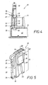
- a stop element 38 which here consists of an elastically molded button which, as illustrated in FIG. 4, produces an edge 39 which projects from the flat profile 48.
- control member 30 is pushed in by means of its handle 32 in the direction of the arrow 47 until, according to FIG. 4, the button 38 with its free button edge 39 abuts the upper end face 49 of the housing guide 46, which thus acts as a counter shoulder for the button 38 forms. 4, the key edge 39 can already engage with a tooth 59 in the guide 46 to ensure this stop action.
- control member 30 is provided with special control surfaces 50, which in the present case consist of a longitudinal groove running at an angle to the direction of movement 47, 47 'of the slide 30. These are assigned complementary counter surfaces 51 in the slide 12, which here consist of a longitudinal rib 51, which can be seen best from FIG.
- the complementary longitudinal ribs 51 are also arranged opposite one another in an opening 52 in the slide 12.
- This opening 52 is arranged in a continuation of the guide 46 located in the housing 11 and although it has an opening width 53 which is adapted to the control member flat profile 48 and can be seen in FIG. 2, it has an opening length 54 which exceeds the flat profile 48 39, 49 immersed depth 55 of the control member 30 in the housing 11, which can be seen from FIG. 1, the control surface 50 on the link 30 with the engagement area 56 shown in FIG. 1 already partially engages the counter surface 51 on the slide 12. This is one in the sense of the counter-arrow 14 'of FIG. 1, it is no longer possible to pull the slide 12 out of the housing 11.
- control member 30 projects with a section 60 from its guide 46 in the housing 11.
- This section 60 is an unmistakable signal that indicates the correct mounting position of the slide 12 in the housing 11. The fitter recognizes that he can now reliably perform the aforementioned assembly 45 of the individual contact members 20.
- the fitter can only move the control member 30 further in the direction of the further push-in arrow 57 in FIG. 3 if the stop action 39, 49 of the button 38 is eliminated. This is done, as can be seen from FIG. 4, by pressing the key 38 in the direction of the pivoting arrow 65 and pressing the key edge 39, which until then has been blocking, into the flat profile 48 of the control element, so that the entire key 38 with the inside width 66 of the key Housing guide 46 is aligned. The control member 30 can then be pressed into the structural unit comprising the housing 11 and the slide 12 up to the full immersion depth 55 '.
- This immersion depth 55 ' is limited in the insertion sense 57 by the abutment lugs 61 which can be seen in FIG. 5 abutting the end faces 49 of the control member guide 46 in the housing 11 in the area of its handle 32.
- the control surfaces 50 located on the control member 30 slide on the slide-side counter surfaces 51 and lead to the thrust movement illustrated by the arrow 15 'in FIG. 3. In terms of direction, this is opposite to the insertion movement 14 of the slide 12 described in connection with FIG. 1.
- control member 30 protrudes only by a small section 60 'according to FIG. 3 from the housing 11 and thus signals the completion of this particular thrust position of the slide 12, which for reasons to be explained in more detail below will be referred to briefly as the "locking position". Accordingly, this working position of the control member 30 is hereinafter referred to as the "locking position”.
- the locking position of the control member 30 which can be seen in FIG. 3 is, however, also secured against an unintentional pull-out movement in the direction of the arrow 57 ', because the above-mentioned upper latch 35 now interacts with a projection 63 provided in the guide 46 of the control member 30.
- the immersion depth 55 ' is thus fixed in both directions of movement 57, 57'.
- the locking position of the slider 12 is of course also precisely defined by means of the surfaces 50, 51 that have moved into one another. In this locking position, the previously assembled contact members 20 are captively fixed in the housing 11 and in the slide 12, which is accomplished in the following manner.
- the position of the contact members 20 in the coupling half 10 is thus fixed; the contact members can no longer be dismantled in the direction of the arrow 45 'of FIG. 3.
- This secured position of the contact members 20 in the coupling half 10 is signaled by the small projecting section 60 'of the control member 30. The fitter can be confident that the coupling half 10 is completed.
- the control member 30 To carry out the disassembly 45 ', the control member 30 must first be pulled out of its housing guide 46 in the direction of the outward arrow 57'. For this purpose, a certain amount of force is deliberately required in order to overcome the above-mentioned, engaged two locking element halves 35, 63. This extension movement 57 'is then again determined by the further locking element pair 34, 58 described in connection with FIG. 1. This is also audible to the fitter, because at the same time the elastic button 38 snaps out of the housing guide 46, which is pushed back into the flat profile 48 of the control member 30, into the position shown in FIG. 4.
- the two surfaces 50, 51 act again between the control member 30 and the slide 12 and provide the aforementioned pushing movement 15 of the slide 12 by the distance 44 mentioned.
- the contact members 20 are unlocked and can be pulled out of the two sections 23, 22 of the bores in the sense of the dismantling arrow 45 'of FIG. 1.
- the contact members 20 can be exchanged or corrected. Because the handle 32 protrudes around the mentioned section 60 ', the pull-out movement 57' of the control member 30 can be carried out conveniently and quickly.
- the handle 32 is provided with an opening 64 into which a tool, such as a screwdriver, is inserted and a lever movement on the control member 30 is permitted.
- the mounting position of the slider 12 shown in FIG. 1 could be secured instead of the stops 41, 42 there by holding elements (not shown) between the slider 12 and the housing 11, which are arranged in the region of the housing slot 13 and z . B. interact like a snap.
- the thrust direction 15 'of FIG. 3 could also be oriented in the same direction instead of in the opposite direction to the preceding insertion movement 14. After the insertion movement 14, the slide 12 would then be moved further into its locking position 15 'in the same direction.
Landscapes
- Details Of Connecting Devices For Male And Female Coupling (AREA)
- Connector Housings Or Holding Contact Members (AREA)
- Measurement And Recording Of Electrical Phenomena And Electrical Characteristics Of The Living Body (AREA)
- Coupling Device And Connection With Printed Circuit (AREA)
- Connections By Means Of Piercing Elements, Nuts, Or Screws (AREA)
Abstract
Description
Die Erfindung richtet sich auf eine mehrpolige Kupplungshälfte der im Oberbegriff des Anspruches 1 angegebenen Art. Diese kann als Stecker mit patrizenförmigen Kontaktgliedern oder als Steckdose mit matrizenförmigen Kontaktgliedern ausgebildet sein.The invention is directed to a multi-pole coupling half of the type specified in the preamble of claim 1. This can be designed as a plug with male contact members or as a socket with female contact members.
Bei der bekannten Kupplungshälfte (DE-OS 30 23 313) ist das Gehäuse mit einer Schar von parallelen Bohrungen zur Aufnahme und Halterung der Kontaktglieder ausgerüstet und besitzt einen diese querenden Schlitz, worin eine als Schieber fungierende Platte schubartig bewegbar ist. Die Lochplatte hat ein dem Bohrungsprofil angepaßtes Lochmuster und greift bei vollem Einschub in Ausnehmungen der Kontaktglieder ein, wodurch diese im Gehäuse gesichert sind. Anstelle einer Lochplatte könnte zur Sicherung der aufgenommenen Kontaktglieder auch ein sogenannter "Kamm" dienen, dessen Kammzinken mit den Kontaktgliedern im Gehäuse zusammenwirken.In the known coupling half (DE-OS 30 23 313), the housing is equipped with a family of parallel bores for receiving and holding the contact members and has a slot crossing these, in which a plate acting as a slide can be moved in a push-like manner. The perforated plate has a hole pattern adapted to the bore profile and, when fully inserted, engages in recesses in the contact members, as a result of which these are secured in the housing. Instead of a perforated plate, a so-called "comb" could also be used to secure the received contact members, the comb teeth of which interact with the contact members in the housing.
Es sind auch Kupplungshälften bekannt (DE-PS 37 35 205), bei denen die Lochungen im Schieber die Funktion übernehmen, die zur Halterung der Kontaktglieder dienende Aufnahmeabschnitte der Gehäusebohrungen zu bilden. Beim Überführen zwischen seiner Montage- und Verriegelungslage wird der Schieber gemeinsam mit den Kontaktgliedern bewegt.Coupling halves are also known (DE-PS 37 35 205), in which the perforations in the slide take over the function of forming the receiving sections of the housing bores which serve to hold the contact members. When moving between its mounting and locking position, the slide is moved together with the contact members.
Aus Gründen der Platzersparnis, die eine kompakte Bauweise fordert, ist der Schubweg des Schiebers zwischen seiner Montage- und Verriegelungslage relativ klein. Deshalb bedarf es großer Aufmerksamkeit, um festzustellen, ob sich der Schieber während bzw. nach der Montage der Kontaktglieder in der ordnungsgemäßen Montagelage bzw. Verriegelungslage befindet. Dies ist bei einem hektischen Montagebetrieb nicht immer leicht erkennbar und führt zu Fehlern. Im Gebrauchsfall ist aufgrund einer engen Anordnung der Kupplungshälfte der Schieber schlecht zugänglich und daher die Bewegung des Schiebers zwischen seinen beiden Schublagen manchmal nur schwierig ausführbar. Außerdem ist nicht nur die Überführung des Schiebers in seine Verriegelungsstellung nach vollzogener Montage der Kupplungsglieder erforderlich, sondern manchmal auch eine Rückbewegung des Schiebers in seine Montagelage, wenn ein beschädigtes oder falsch gepoltes Kontaktglied demontiert werden muß. Sofern ein Schieber zur Aufnahme der Kontaktglieder genutzt wird und es sich dabei um Kupplungshälften handelt, die eine große Vielzahl von Kontaktgliedern aufweisen müssen, so ist es schon aus Gewichts- und Reibungsgründen mühevoll, den Schieber manuell zwischen seinen beiden Schublagen zu bewegen. Die Anforderungen an den Monteur sind beträchtlich und wirken sich in einer geringen sowie fehlerhaften Montageleistung aus.In order to save space, which is required by a compact design, the slide path of the slide between its mounting and locking position is relatively small. Therefore, great care must be taken to determine whether the slide is in the correct mounting position or locking position during or after the mounting of the contact members. This is not always easy to recognize in a hectic assembly operation and leads to errors. In use, the slide is difficult to access due to the close arrangement of the coupling half, and therefore the movement of the slide between its two drawers is sometimes difficult to carry out. In addition, not only the transfer of the slide into its locking position after installation of the coupling members is required, but sometimes also a return movement of the slide into its mounting position when a damaged or incorrectly polarized contact member has to be removed. If a slide is used to hold the contact members and it is a matter of coupling halves which must have a large number of contact members, it is difficult, for reasons of weight and friction, to move the slide manually between its two drawers. The requirements for the fitter are considerable and result in a low and faulty assembly performance.
Der Erfindung liegt die Aufgabe zugrunde, eine preiswerte, raumsparende Kupplungshälfte der im Oberbegriff des Anspruches 1 angegebenen Art zu entwickeln, deren Schieber leichtgängig und zuverlässig zwischen seinen beiden Schublagen überführbar macht, wobei unmißverständlich erkennbar ist, in welcher seiner beiden Schublagen sich der Schieber gerade befindet. Dies wird erfindungsgemäß durch die im Kennzeichen des Anspruches 1 angeführten Maßnahmen erreicht, denen folgende besondere Bedeutung zukommt.The invention has for its object to develop an inexpensive, space-saving coupling half of the type specified in the preamble of claim 1, the slide of which makes it smoothly and reliably transferable between its two drawers, it being unmistakably recognizable in which of its two drawers the slide is currently located . This is achieved according to the invention by the measures specified in the characterizing part of claim 1, which have the following special significance.
Das die Erfindung kennzeichnende Steuerglied hat eine doppelte Funktion zu erfüllen. Einerseits dient es zu einer besonders leichtgängigen und bequemen Bewegung des Schiebers im Gehäuse zwischen dessen beiden Schublagen. Dies wird erreicht, weil durch die Steuer- und Gegenflächen ein Übersetzungsverhältnis erreicht wird, das auch gewichtige große Schieber mit kleiner manueller Kraft zu verschieben gestattet. Damit lassen sich kleine Schubbewegungswege zuverlässig durch längere Bewegungen des Steuerglieds bequem erzeugen. Man kann jetzt das Steuerglied richtungsmäßig so setzen, wie es für die manuelle Handhabung am Gehäuse am günstigsten ist und ist nicht mehr auf die Schubbewegungsrichtung des Schiebers festgelegt. Die Führungsrichtung des Steuerglieds kann nämlich grundsätzlich in einer anderen Richtung als die Schubbewegung des Schiebers weisen. Andererseits erfüllt das Steuerglied gleichzeitig die Funktion einer optischen Anzeige, die aufgrund der unterschiedlichen Höhenlage des Steuerglieds bezüglich des Gehäuses eindeutig signalisiert, ob der Schieber sich in seiner Montagelage oder in seiner endgültigen Verriegelungslage befindet. Die aus der Übersetzung der Bewegungen zwischen dem Steuerglied einerseits und dem Schieber andererseits sich ergebenden großen Wegstrecken beim Steuerglied sind für eine solche Anzeige besonders günstig.The control element characterizing the invention has a dual function. On the one hand, it serves for a particularly smooth and comfortable movement of the slide in the housing between its two drawers. This is achieved because a control ratio is achieved through the control and counter surfaces, which also allows weighty large slides to be moved with little manual force. Small thrust movement paths can thus be reliably and comfortably generated by longer movements of the control member. You can now set the control element in the direction that is most favorable for manual handling on the housing and is no longer restricted to the direction of thrust of the slide. The guiding direction of the control element can in principle point in a different direction than the pushing movement of the slide. On the other hand, the control element simultaneously fulfills the function of an optical display which, due to the different height of the control element with respect to the housing, clearly signals whether the slide is in its mounting position or in its final locking position. The long distances in the control element resulting from the translation of the movements between the control element on the one hand and the slide on the other hand are particularly favorable for such a display.
Ein solches Steuerglied könnte zwar schwenkbeweglich sein, doch ist es gemäß Anspruch 2 einfacher, das Steuerglied parallel zu sich selbst im Gehäuse verschiebbar zu machen. Am günstigsten für die Kraftübertragung ist es, das Steuerglied senkrecht zur Schubrichtung des Schiebers gemäß Anspruch 3 verlaufen zu lassen. Sofern man eine Handhabe nach Anspruch 4 vorsieht, ist damit nicht nur die Betätigung des Steuerglieds vereinfacht, sondern zugleich die erwähnte Signalwirkung zum Erkennen der jeweiligen Schieberlage verbessert. Man wird dabei bestrebt sein, die Wegstrecken gemäß Anspruch 5 zu wählen.Such a control element could be pivotable, but according to claim 2 it is easier to make the control element displaceable parallel to itself in the housing. The cheapest for the power transmission is to let the control member run perpendicular to the direction of thrust of the slide according to claim 3. If one provides a handle according to claim 4, this not only simplifies the actuation of the control element, but at the same time improves the aforementioned signal effect for recognizing the respective slide position. One will endeavor to choose the routes according to claim 5.
Die Arbeitsstellungen des Steuerglieds sollte man durch Rastelemente gemäß Anspruch 6 plazieren, was bei der Handhabe spürbar und hörbar die vorerwähnte Signalwirkung steigert. Es empfiehlt sich dabei den jeweiligen Bedürfnissen angepaßte Rastelemente zu verwenden, die gemäß Anspruch 7 beide Arbeitsstellungen des Steuerschiebers getrennt versorgen. Zusätzlich sollte man für eine besonders markante Montagestellung des Steuerglieds ein Anschlagelement nach Anspruch 8 verwenden, das sich am einfachsten in Form einer formelastischen Taste nach Anspruch 9 gestalten läßt. Dementsprechend kann man die Verriegelungsstellung durch eine Anschlagnase nach Anspruch 11 festlegen. Eine raumsparende Anordnung der Gegenflächen für das Steuerglied läßt sich in einem Durchbruch gemäß Anspruch 12 verwirklichen, wobei die Ausbildung dieser Gegenflächen als Rippe und der Steuerflächen als Nut gemäß Anspruch 13 am vorteilhaftesten ist.The working positions of the control member should be placed by latching elements according to claim 6, which noticeably and audibly increases the aforementioned signal effect in the handle. It is recommended to meet the respective needs Fit locking elements to use, which separately supply both working positions of the control slide according to claim 7. In addition, one should use a stop element according to claim 8 for a particularly striking mounting position of the control member, which can be designed most simply in the form of a resilient button according to claim 9. Accordingly, you can set the locking position by a stop lug according to
Eine besonders bequeme Anordnung des Steuerglieds an der Kupplungshälfte ergibt sich durch die in Anspruch 10 hervorgehobene Anordnung, die mit der Montagerichtung der Kontaktglieder im Bereich des Gehäuses ausgerichtet ist. Die Montagestellung des Steuerglieds läßt sich zusätzlich oder ergänzend zu den vorerwähnten Rastelementen auch noch durch einen bereichsweisen Eingriff der Steuer- und Gegenflächen gemäß Anspruch 14 erzielen. Auch die Schublage des Schiebers sollte durch Haltelemente gemäß Anspruch 16 gesichert sein. Alternativ ist es in vorteilhafter Weise möglich, hierfür Anschläge gemäß Anspruch 15 zu verwenden, die insbesondere in Form von Endanschlägen zwischen Schieber und Gehäuse ausgebildet sind. Letzteres bringt eine besonders exakte Positionierung der Bauteile während des Montagevorgangs der Kupplungsglieder.A particularly convenient arrangement of the control member on the coupling half results from the arrangement emphasized in
Aus baulichen Gründen empfiehlt es sich, die Schubbewegungsrichtung gemäß Anspruch 17 in Ausrichtung mit dem Verlauf eines Einsteckschlitzes für das Einbringen des Schiebers im Gehäuse anzuordnen. Die Überführung des Schiebers zwischen seinen beiden Schublagen kann, in Abhängigkeit vom jeweiligen Anwendungsfall, entweder im Sinne des Anspruches 18 gegensinnig oder gemäß Anspruch 19 gleichsinnig erfolgen.For structural reasons, it is advisable to arrange the direction of thrust movement in alignment with the course of an insertion slot for inserting the slide in the housing. The transfer of the slide between its two drawers can, depending on the respective application, either in the sense of
Die Erfindung eignet sich in besonders vorteilhafter Weise für Schieber, deren Lochmuster gleichzeitig die Aufnahmeabschnitte zur Halterung der Kontaktglieder gemäß Anspruch 20 bildet. Durch das Steuerglied lassen sich nämlich große Gewichte und große Reibungskräfte überwinden. In diesem Fall empfiehlt es sich schließlich auch, gemäß Anspruch 21, den Versatz der im Schieber befindlichen Aufnahmeabschnitte gegenüber Eingangsabschnitten der Bohrungen im Gehäuse dazu zu nutzen, um die Kontaktierung fehlerhafter Kupplungshälften grundsätzlich auszuschließen. Die Bewegungsstrecken der Kontaktglieder lassen sich durch entsprechende Verbreiterungen in Ausgangsabschnitten der Bohrungen im Gehäuse gemäß Anspruch 22 berücksichtigen. Diese können schließlich zugleich vorteilhaft gemäß Anspruch 23 zur Sicherung der Kontaktglieder im Gehäuse genutzt werden.The invention is particularly advantageously suitable for slides, the hole pattern of which at the same time forms the receiving sections for holding the contact members. The control element can overcome large weights and large frictional forces. In this case, it is finally also advisable, according to
Weitere Maßnahmen und Vorteile der Erfindung ergeben sich aus der nachfolgenden Beschreibung und den Zeichnungen. Die Erfindung richtet sich dabei auf alle daraus entnehmbaren neuen Merkmale und Merkmalskombinationen, auch wenn diese nicht ausdrücklich in den Ansprüchen angeführt sein sollten. In den Zeichnungen ist die Erfindung in einem Ausführungsbeispiel dargestellt. Es zeigen:
- Fig. 1 in Vergrößerung die Längsschnittansicht durch ein Teilstück der erfindungsgemäßen Kupplungshälfte, bei welcher sich ein Schieber in seiner ersten Arbeitslage, nämlich einer Montagelage zum Einstecken bzw. Wiederherausziehen von Kontaktgliedern befindet,
- Fig. 2 eine Querschnittansicht durch den Schieber längs der Schnittlinie 11-11 von Fig. 1,
- Fig. 3 einen der Fig. 1 entsprechenden Längsschnitt durch die Kupplungshälfte, wenn sich der Schieber in seiner anderen Schublage, nämlich einer Verriegelungslage befindet,
- Fig. 4 eine Seitenansicht der Kupplungshälfte längs der versprungenen Schnittlinie IV-IV von Fig. 1 und
- Fig. 5 in vergrößerter perspektivischer Darstellung ein bei der erfindungsgemäßen Kupplungshälfte zur Bewegung des Schiebers dienendes Steuerglied.
- 1 is an enlarged longitudinal sectional view through a section of the coupling half according to the invention, in which a slide is in its first working position, namely an assembly position for inserting or removing contact members,
- 2 shows a cross-sectional view through the slide along the section line 11-11 of FIG. 1,
- 1 corresponding longitudinal section through the coupling half when the slide is in its other thrust position, namely a locking position,
- Fig. 4 is a side view of the coupling half along the section line IV-IV of Fig. 1 and
- Fig. 5 in an enlarged perspective view of a control member serving to move the slide in the coupling half according to the invention.
Eine Kupplungshälfte 10 umfaßt gehäusemäßig zwei Bestandteile, nämlich ein Gehäuse 11 und einen Schieber 12. Das Gehäuse 11 ist mit einem an seiner einen Seite offenen Gehäuseschlitz 13 versehen, worin der Schieber 12 im Sinne des Pfeils 14 eingesteckt wird und nach dem Einstekken im Gehäuseinneren zwischen zwei definierten Schublagen gemäß Fig. 1 und 2 im Sinne der Pfeile 15 bzw. 15' hin- und herbewegbar ist. Sowohl das Gehäuse 11 als auch der Schieber 12 sind mit aufeinander abgestimmten, längsprofilierten Bohrungen versehen, die sich in drei aufeinanderfolgende Abschnitte gliedern lassen, nämlich einen Eingangsabschnitt 21 im Bereich des Gehäusebodens 16, der nach außen konisch erweitert sein kann. Ferner gehört dazu ein ausschließlich im Bereich des Schiebers 12 befindlicher Aufnahmeabschnitt 22, der mit inneren Halteflächen 17 versehen ist zur einzelweisen Aufnahme und exakten Positionierung von Kontaktgliedern 20. Schließlich umfaßt die Bohrung noch Ausgangsabschnitte 23, die im Gehäusedeckel 18 sich befinden und dort nach außen hin offene Kammern zum Einführen der Kontaktglieder 20 bilden. An der Übergangsstelle zwischen den Aufnahme- und Ausgangsabschnitten 22, 23 befinden sich Absatzflächen 19, die in der strichpunktiert in Fig. 3 angedeuteten Schnittebene 29 zwischen dem Schieber 12 und dem Gehäuse 11 liegen und mit entsprechenden Schultern 24 des eingeführten Kontaktglieds 20 zusammenwirken.A
Dazu ist das Kontaktglied in mehrere Teile gegliedert, nämlich einen die eigentlichen Kontaktfedern umfassenden Funktionsteil 25, einen ggf. mit Verriegelungszungen ausgerüsteten Mittelteil 26 und einem zum Anschluß einer Leitung 40 dienenden Endteil 27. Zwischen dem End- und Mittelteil 26 befindet sich die bereits erwähnte Schulter 24. Diese Kontaktglieder 20 werden in folgender Weise in den beiden Gehäusebestandteilen 11, 12 montiert.For this purpose, the contact member is divided into several parts, namely a
Die beiden Bestandteile 11, 12 werden, voneinander getrennt, aus Kunststoff hergestellt. Durch die Aufnahmeabschnitte 22 besitzt der Schieber 12 ein mit den angrenzenden Bohrungsabschnitten 21, 23 des Gehäuses 11 abgestimmtes Lochmuster. Es ist eine große Vielzahl solcher Löcher 22 vorgesehen, um eine Schar dazu passender Kontaktglieder 20 aufzunehmen und zu haltern. Dazu wird der Schieber 12 zunächst im Sinne des bereits erwähnten Pfeils 14 so tief in den Gehäuseschlitz 13 eingesteckt, bis das innere Schieberende 41 an einen als Gehäuseabschluß dienenden Endanschlag 42 des Gehäuses 11 anstößt. Es liegt dann eine definierte, aus Fig. 1 ersichtliche Schublage vor, in welcher die Lochmuster 22 des Schiebers 12 mit den Ausgangsabschnitten 23 des Gehäuses 11 ausgerichtet sind. Demgegenüber sind aber die im vorerwähnten Gehäuseboden 16 befindlichen Eingangsabschnitte 21 der Bohrungen um eine in Schubbewegungsrichtung weisende Wegstrecke 44 zunächst versetzt und durch Wandteile 43 des Schiebers 13 versperrt. Damit ist ausgeschlossen, daß nicht näher gezeigte Gegenkontaktglieder einer zu dieser Kupplungshälfte 10 komplementären Gegenkupplungshälfte über die erwähnten trichterförmigen Erweiterungen durch die Eingangsabschnitte 21 in den Höhenbereich des Schiebers 12 eingesteckt werden können.The two
Weil die Bohrungsabschnitte 22, 23 miteinander ausgerichtet sind, lassen sich in dieser Schublage die Kontaktglieder im Sinne des in Fig. 1 angedeuteten Montagepfeils 45 in das Gehäuse 11 und in den Schieber 12 einstecken, bis sie mit ihren Funktionsteilen 25 ordnungsgemäß in den inneren Halteflächen 17 zu liegen kommen und dabei mit ihren bereits erwähnten Federzungen od. dgl. im Bereich ihres Mittelteils 26 im Gehäuse 11 einschnappen. Wegen der durchzuführenden Montage soll daher nachfolgend die in Fig. 1 gezeigte Schublage 12 des Schiebers kurz als "Montagelage" bezeichnet werden.Because the
Diese Montagelage des Schiebers 12 im Gehäuse 11 ist durch ein besonderes Steuerglied 30 gesichert, dessen Aussehen am besten aus der perspektivischen Darstellung von Fig. 5 erkennbar ist. Das Steuerglied 30 umfaßt einen Führungsbereich 31 mit einer sich daran anschließenden Handhabe 32. Diesem Führungsbereich 31 ist im Höhenbereich des Gehäusedeckels 18 eine Führung 46 zugeordnet, die eine Parallelführung des Steuerglieds 30 im Sinne des Führungspfeils 47 von Fig. 1 bzw. 57 von Fig. 3 gestattet. Diese Führungsrichtung 47, 57 des Steuerglieds 30 ist senkrecht zur vorerwähnten Schubbewegung 15, 15' des Schiebers 12 im Gehäuse 11 orientiert und verläuft somit parallel zu der genannten Montagerichtung 45 der Kontaktglieder 20, und zwar von der gleichen Gehäuseseite aus. Daher ist das Steuerglied 30 mit seiner Handhabe 32 genauso bequem zugänglich, wie die Bohrungsabschnitte 23, 22 für die Montage 45 der Kontaktglieder 20.This mounting position of the
Ausweislich der Fig. 5 besitzt das Steuerglied 30 in seinem Führungsbereich 31 eine angeformte Leiste 33, die zwei zueinander höhenversetzte Rastelementhälften 34, 35 in Form von Rastnasen trägt. Zur Erhöhung der Formelastizität der unteren Rastnase 34 des ebenfalls aus Kunststoff ausgebildeten Steuerglieds 30 ist eine Kerbe 36 vorgesehen. Aus gleichem Grund ist im Höhenbereich der oberen Rastnase 35 die Leiste 33 mit einem Ausschnitt 37 ausgerüstet. Inmitten des Führungsbereichs 31 des Steuerglieds 30 ist schließlich ein Anschlagelement 38 angeordnet, das hier aus einer formelastisch angeformten Taste besteht, die eine normalerweise, wie Fig. 4 verdeutlicht, aus dem Flachprofil 48 vorspringende Kante 39 erzeugt.5, the
Die Montagelage des Schiebers 12 wird, ausweislich der Fig. 1, durch den Schieber 30 gesichert. Dazu wird das Steuerglied 30 mittels seiner Handhabe 32 soweit im Sinne des Pfeils 47 eingeschoben, bis, gemäß Fig. 4, die Taste 38 mit ihrer freien Tastenkante 39 an die obere Stirnfläche 49 der Gehäuseführung 46 stößt, die somit eine Gegenschulter für die Taste 38 bildet. Um diese Anschlagwirkung sicherzustellen, kann, ausweislich der Fig. 4, die Tastenkante 39 mit einem Zahn 59 in die Führung 46 dabei bereits eingreifen. In seinem Führungsbereich 31 ist das Steuerglied 30 mit besonderen Steuerflächen 50 versehen, die im vorliegenden Fall aus einer geneigt zur Bewegungsrichtung 47, 47' des Schiebers 30 verlaufenden Längsnut bestehen. Diesen sind komplementäre Gegenflächen 51 im Schieber 12 zugeordnet, die hier aus einer am besten aus Fig. 2 erkennbaren, entsprechend geneigt verlaufenden Längsrippe 51 bestehen. Weil die von den Längsnuten 50 gebildeten Steuerflächen auf beiden Breitseiten des Steuerglied-Flachprofils 48 sich befinden, sind auch die komplementären Längsrippen 51 einander gegenüberliegend in einem Durchbruch 52 des Schiebers 12 angeordnet. Dieser Durchbruch 52 ist in Fortsetzung der im Gehäuse 11 befindlichen Führung 46 angeordnet und besitzt zwar eine dem Steuerglied-Flachprofil 48 angepaßte, aus Fig. 2 erkennbare Durchbruchsbreite 53, aber eine das Flachprofil 48 übersteigende Durchbruchs-Länge 54. Wenn die durch die Anschlagwirkung bei 39, 49 festgelegte, aus Fig. 1 erkennbare Eintauchtiefe 55 des Steuerglieds 30 im Gehäuse 11 vorliegt, hintergreift die Steuerfläche 50 am Glied 30 mit dem aus Fig. 1 ersichtlichen Eingriffsbereich 56 bereits teilweise die Gegenfläche 51 am Schieber 12. Dadurch ist eine im Sinne des Gegen-Pfeils 14' von Fig. 1 verdeutlichte Herausziehbewegung des Schiebers 12 aus dem Gehäuse 11 nicht mehr möglich.The mounting position of the
Aber auch eine Ausziehbewegung des Steuerglieds 30 im Sinne des in Fig. 1 angedeuteten Pfeils 47' ist nicht mehr möglich, weil die untere Rastnase 34 eine in, Höhenbereich der bereits erwähnten Schnittebene 49 liegende Absatzfläche 58 des Gehäuses 11 hintergreift, die damit die zur Rastnase 34 komplementäre Rastelementhälfte bildet. Dadurch ist die Eintauchtiefe 55 des Steuerglieds 30 im Gehäuse 11 auch im Herausziehsinne 47' gesichert; das Steuerglied 30 befindet sich somit in einer genau definierten Arbeitsstellung, welche die vorerwähnte ausgerichtete Montagelage zwischen dem Schieber 12 und dem Gehäuse 11 sicherstellt und daher nachfolgend kurz "Montagestellung" bezeichnet werden soll. Wegen der definierten Eintauchtiefe 55 ragt das Steuerglied 30 mit einem Teilstück 60 aus seiner Führung 46 im Gehäuse 11 heraus. Dieses Teilstück 60 ist ein unübersehbares Signal, das die ordnungsgemäße Montagelage des Schiebers 12 im Gehäuse 11 anzeigt. Der Monteur erkennt, daß er nun zuverlässig die vorerwähnte Montage 45 der einzelnen Kontaktglieder 20 ausführen kann.However, a pull-out movement of the
Ist die Montage 45 aller Kontaktglieder 20 vollzogen, so kann der Monteur das Steuerglied 30 im Sinne des weiteren Eindrückpfeils 57 von Fig. 3 nur dann weiterbewegen, wenn die Anschlagwirkung 39, 49 der Taste 38 beseitigt wird. Dies geschieht, wie aus Fig. 4 ersichtlich dadurch, daß man die Taste 38 im Sinne des Schwenk-Pfeils 65 betätigt und die bis dahin sperrwirksame Tastenkante 39 in das Flachprofil 48 des Steuergliedseindrückt, so daß die ganze Taste 38 mit der lichten Weite 66 der Gehäuseführung 46 fluchtet. Dann kann das Steuerglied 30 bis zur vollen Eintauchtiefe 55' in die Baueinheit aus Gehäuse 11 und Schieber 12 eingedrückt werden. Diese Eintauchtiefe 55' ist im Einführungssinne 57 dadurch begrenzt, daß die in Fig. 5 erkennbaren Anschlagnasen 61 im Bereich seiner Handhabe 32 an die bereits erwähnten Stirnflächen 49 der Steuerglied-Führung 46 im Gehäuse 11 stoßen. Bei diesem Eindrücken 57 gleiten die am Steuerglied 30 befindlichen Steuerflächen 50 an den schieberseitigen Gegenflächen 51 und führen zu der aus Fig. 3 durch den Pfeil 15' verdeutlichten Schubbewegung. Diese ist richtungsmäßig zu der im Zusammenhang mit Fig. 1 beschriebenen Einsteckbewegung 14 des Schiebers 12 entgegengesetzt. Im vorliegenden Fall erfolgt also wieder eine Rückschubbewegung 15' um eine von den zusammenwirkenden Flächen 40, 51 bestimmte, definierte Wegstrecke 44 vor, wobei sich die vorausgehend aneinanderliegenden Flächen des Schieberendes 41 und des Gehäuseendanschlags 42 ausweislich der Fig. 3 wieder etwas voneinander wegbewegen. Jetzt ragt das Steuerglied 30 lediglich um ein kleines Teilstück 60' gemäß Fig. 3 aus dem Gehäuse 11 heraus und signalisiert damit den Vollzug dieser besonderen Schublage des Schiebers 12, der aus nachfolgend noch näher zu erläuternden Gründen kurz als "Verriegelungslage" bezeichnet werden soll. Dementsprechend wird diese Arbeitsstellung des Steuerglieds 30 nachfolgend "Verriegelungsstellung" genannt.Once all the
Wie ein Vergleich der beiden Arbeitsstellungen des Steuerglieds 30 in Fig. 1 und 3 zeigt, ist dieser in der Verriegelungsstellung um ein beträchtliches Längenstück 62 ins Gehäuse 11 eingetaucht, was für den Monteur ein unübersehbares Signal für die ordnungsgemäße Verriegelungslage des Schiebers 12 ist. Durch die Form der Führungsflächen 50, 51 liegt ein günstiges Übersetzungsverhältnis der Bewegungen 57 einerseits und 15' andererseits zwischen dem Steuerglied 30 und dem Schieber 12 vor, was trotz großer Massen und hoher Reibungsverluste für eine leichtgängige Überführung des Schiebers 12 zwischen seinen beiden Arbeitslagen von Fig. 1 und 3 sorgt. Die Wegstrecke 62 beim Eindrücken 57 des Steuerglieds 30 ist vielfach größer als die vorgenannte Wegstrecke 44 des Schieber-Schubs 15'.As a comparison of the two working positions of the
Die aus Fig. 3 erkennbare Verriegelungsstellung des Steuerglieds 30 ist aber auch gegenüber einer unbeabsichtigten Herausziehbewegung im Sinne des Pfeils 57' gesichert, weil jetzt die bereits erwähnte obere Rastnase 35 mit einem in der Führung 46 des Steuerglieds 30 vorgesehenen Vorsprung 63 zusammenwirkt. Die Eintauchtiefe 55' ist also in beiden Bewegungsrichtungen 57, 57' festgelegt. Aufgrund der feststehenden Arbeitsstellung ist zugleich über die ineinandergefahrenen Flächen 50, 51 natürlich auch die Verriegelungslage des Schiebers 12 genau festgelegt. In dieser Verriegelungslage sind die vorausgehend montierten Kontaktglieder 20 unverlierbar im Gehäuse 11 und im Schieber 12 festgelegt, was auf folgende Weise zustande kommt.The locking position of the
Bei dem vorgenannten Rückschub 15' des Schiebers 12 werden die in den Aufnahmeabschnitten 22 des Schiebers 12 steckenden Kontaktglieder 20 mitbewegt, und zwar im gleichen Sinn und um die gleiche Wegstrecke 44, wie der Vergleich zwischen Fig. 1 und 3 veranschaulicht. Dadurch bewegen sich auch die zum Anschluß der Leitungen 40 dienenden Kontaktglied-Endteile 27 mit. Diesem Umstand ist in den Bohrungs-Ausgangsabschnitten 23 des Gehäuses 11 dadurch Rechnung getragen, daß dort die Bohrungen mit Verbreiterungen 28 gemäß Fig. 1 versehen sind, in welche sich nun diese Endteile 27 quer hineinbewegen können. Gleichzeitig bewegen sich damit die vorbeschriebenen Schultern 24 unter die erwähnten Absatzflächen 19 im Gehäuse 11 und es kommt zu einer Verriegelung der Kontaktglieder 20 in den Aufnahmeabschnitten 22 des Schiebers 12. Die Position der Kontaktglieder 20 in der Kupplungshälfte 10 ist damit festgelegt; die Kontaktglieder lassen sich nicht mehr im Sinne des Bewegungspfeils 45' von Fig. 3 demontieren. Diese gesicherte Lage der Kontaktglieder 20 in der Kupplungshälfte 10 ist durch das kleine herausragende Teilstück 60' des Steuerglieds 30 signalisiert. Der Monteur kann zuversichtlich sein, daß die Kupplungshälfte 10 fertiggestellt ist.In the aforementioned push-
Um die Demontage 45' auszuführen, muß das Steuerglied 30 zunächst im Sinne des Herausfahr-Pfeils 57' aus seiner Gehäuseführung 46 herausgezogen werden. Dazu ist bewußt ein gewisser Kraftaufwand erforderlich, um die vorerwähnten in Eingriff stehenden beiden Rastelementhälften 35, 63 zu überwinden. Diese Ausfahrbewegung 57' wird dann wieder durch das im Zusammenhang mit Fig. 1 beschriebene weitere Rastelement-Paar 34, 58 festgelegt. Dies ist auch für den Monteur hörbar, weil gleichzeitig die elastische Taste 38 aus der sie ins Flachprofil 48 des Steuerglieds 30 rückgedrückt gehaltenen Gehäuseführung 46 in die aus Fig. 4 erkennbare Position herausschnappt. Bei dieser Herausziehbewegung 57' wirken wieder die beiden Flächen 50, 51 zwischen dem Steuerglied 30 und Schieber 12 und sorgen für die bereits erwähnte Schubbewegung 15 des Schiebers 12 um die erwähnte Wegstrecke 44. Es liegt dann wieder exakt die aus Fig. 1 ersichtliche Montagelage des Schiebers 12 vor. Die Kontaktglieder 20 sind entriegelt und können im Sinne des Demontage-Pfeils 45' von Fig. 1 aus den beiden Abschnitten 23, 22 der Bohrungen herausgezogen werden. Es kann ein Austausch oder eine Korrektur der Kontaktglieder 20 vorgenommen werden. Weil die Handhabe 32 um das erwähnte Teilstück 60' herausragt, ist die Herausziehbewegung 57' des Steuerglieds 30 bequem und schnell ausführbar. Um das Herausziehen 57' zu unterstützen, ist die Handhabe 32 mit einem Ausbruch 64 versehen, in welchen ein Werkzeug, wie ein Schraubenzieher, eingeführt und eine Hebelbewegung am Steuerglied 30 zuläßt.To carry out the disassembly 45 ', the
In Abwandlung des dargestellten Ausführungsbeispiels könnte man die in Fig. 1 gezeigte Montagelage des Schiebers 12 anstelle der dortigen Anschläge 41, 42 auch durch nicht näher gezeigte Haltelemente zwischen dem Schieber 12 und dem Gehäuse 11 sichern, die im Bereich des Gehäuseschlitzes 13 angeordnet sind und z. B. rastartig zusammenwirken. Zusätzlich oder alternativ könnte auch die Schubrichtung 15' von Fig. 3 statt im Gegensinne zu der vorausgehenden Einsteckbewegung 14 auch gleichsinnig zu dieser ausgerichtet sein. Nach der Einsteckbewegung 14 würde der Schieber 12 dann im gleichen Richtungssinn in seine Verriegelungslage 15' weiter verschoben werden.In a modification of the illustrated embodiment, the mounting position of the
- 10 Kupplungshälfte10 coupling half
- 11 Gehäuse11 housing
- 12 Schieber12 sliders
- 13 Gehäuseschlitz13 housing slot
- 14 Einsteck-Pfeil14 Insert arrow
- 14' Herauszieh-Pfeil14 'Pull-out arrow
- 15 Schubbewegung, Hinbewegungs-Pfeil15 pushing movement, moving arrow
- 15' Schubbewegung, Rückbewegungs-Pfeil15 'pushing movement, return movement arrow
- 16 Gehäuseboden16 case back
- 17 innere Haltefläche in 2217 inner holding surface in 22
- 18 Gehäusedeckel18 housing cover
- 19 Absatzfläche in 1119 sales area in 11
- 20 Kontaktglied20 contact link
- 21 Bohrung, Eingangsabschnitt in 1621 hole, input section in 16
- 22 Bohrung, Aufnahmeabschnitt in 16, Lochmuster22 hole, receiving section in 16, hole pattern
- 23 Ausgangsabschnitt in 18, Kammer23 exit section in 18, chamber
- 24 Verriegelungsschulter an 2024 locking shoulder on 20
- 25 Funktionsteil von 2025 functional part of 20
- 26 Mittelteil von 2026 middle section of 20
- 27 Endteil von 2027 end part of 20
- 28 Verbreiterung von 2328 widening of 23
- 29 Schnittebene von 11, 1229 sectional plane of 11, 12
- 30 Steuerglied30 control element
- 31 Führungsbereich von 3031 leadership area of 30
- 32 Handhabe von 3032 handles of 30
- 33 Leiste an 3033 strips at 30
- 34 Rastelenlenthälfte, Rastnase34 half-length leash, lug
- 35 Rastelementhälfte, Rastnase35 locking element half, locking lug
- 36 Kerbe bei 3436 notch at 34
- 37 Ausschnitt bei 3537 cutout at 35
- 38 Anschlagelement, Taste38 stop element, button
- 39 Tastenkante39 key edge
- 40 Leitung40 line
- 41 inneres Schieberende41 inner slide end
- 42 innerer Endanschlag von 1142 inner end stop of 11
- 43 Wandteil von 12 bei 2143 wall part of 12 at 21
- 44 Wegstrecke des Schubs44 distance of the push
- 45 Montage-Pfeil für 2045 assembly arrow for 20
- 45' Demontage-Pfeil für 2045 'Disassembly arrow for 20
- 46 Führung46 leadership
- 47 Einführrichtungs-Pfeil von 3047 Direction of insertion arrow of 30
- 47' Herausführrichtungs-Pfeil von 3047 'Exit direction arrow from 30
- 48 Flachprofil von 3048 flat profile of 30
- 49 Stirnfläche, Gegenschulter49 end face, counter shoulder
- 50 Steuerfläche von 30, Längsnut50 control surface of 30, longitudinal groove
- 51 Gegenfläche von 12, Längsrippe51 counter surface of 12, longitudinal rib
- 52 Durchbruch in 1252 breakthrough in 12
- 53 Durchbruchs-Breite53 breakthrough width
- 54 Durchbruchs-Länge54 breakthrough length
- 55 Eintauchtiefe in Montagestellung (Fig. 1)55 immersion depth in mounting position (Fig. 1)
- 55' Eintauchtiefe in Verriegelungsstellung (Fig. 3)55 'immersion depth in the locked position (Fig. 3)
- 56 Eingriffsbereich von 5056 engagement range of 50
- 57 Eindrück-Pfeil von 30 (Fig. 3)57 indentation arrow of 30 (Fig. 3)
- 57' Herauszieh-Pfeil von 30 (Fig. 3)57 'pull-out arrow of 30 (Fig. 3)
- 58 Absatzfläche, Rastelementhälfte58 heel area, locking element half
- 59 Zahn an 3959 tooth at 39
- 60 Teilstück von 30 in Montagestellung (Fig. 1)60 section of 30 in the assembly position (Fig. 1)
- 60' Teilstück von 30 in Verriegelungsstellung (Fig. 3)60 'section of 30 in the locked position (Fig. 3)
- 61 Anschlagnase von 3061 stop nose of 30
- 62 Wegstrecke von 30, Längenstück62 distance of 30, length
- 63 Vorsprung, Rastelementhälfte63 projection, locking element half
- 64 Ausbruch in 3264 outbreak in 32
- 65 Schwenkbewegungs-Pfeil von 3865 Swivel movement arrow from 38
- 66 lichte Weite von 4666 clear width of 46
Claims (23)
gekennzeichnet durch
daß in einer ersten Arbeitsstellung des Steuerglieds (30) (Montagestellung) die Montagelage des Schiebers (12) im Gehäuse (11) vorliegt,
während in einer zweiten Arbeitsstellung (Verriegelungsstellung) der Schieber (12) vom Steuerglied (30) in die Verriegelungslage im Gehäuse (11) gebracht ist, (vergl. Fig. 1, 3).1. Multipole pluggable coupling half (10), such as a plug or socket, with a plurality of contact members (20) connected to electrical lines,
marked by
that in a first working position of the control member (30) (mounting position) the mounting position of the slide (12) is in the housing (11),
while in a second working position (locking position) the slide (12) is brought from the control member (30) into the locking position in the housing (11) (see FIGS. 1, 3).
Applications Claiming Priority (2)
| Application Number | Priority Date | Filing Date | Title |
|---|---|---|---|
| DE4029300A DE4029300C1 (en) | 1990-09-15 | 1990-09-15 | Multipole electrical connector - has crimped connectors forced against projections on housing to provide secure retention |
| DE4029300 | 1990-09-15 |
Publications (2)
| Publication Number | Publication Date |
|---|---|
| EP0477610A1 true EP0477610A1 (en) | 1992-04-01 |
| EP0477610B1 EP0477610B1 (en) | 1994-06-08 |
Family
ID=6414314
Family Applications (1)
| Application Number | Title | Priority Date | Filing Date |
|---|---|---|---|
| EP91114898A Expired - Lifetime EP0477610B1 (en) | 1990-09-15 | 1991-09-04 | Multipolar pluggable coupling parts for electrical conductors |
Country Status (4)
| Country | Link |
|---|---|
| EP (1) | EP0477610B1 (en) |
| AT (1) | ATE107082T1 (en) |
| DE (2) | DE4029300C1 (en) |
| ES (1) | ES2057686T3 (en) |
Cited By (2)
| Publication number | Priority date | Publication date | Assignee | Title |
|---|---|---|---|---|
| EP0623973A1 (en) * | 1993-05-07 | 1994-11-09 | Sumitomo Wiring Systems, Ltd. | Connector |
| WO2005107020A1 (en) * | 2004-04-26 | 2005-11-10 | Valeo Electronique Et Systemes De Liaison | Electrical connector box element, electrical contact member which is intended for one such box and tool for removing said electrical members |
Families Citing this family (2)
| Publication number | Priority date | Publication date | Assignee | Title |
|---|---|---|---|---|
| DE4330359C2 (en) * | 1993-09-08 | 1995-06-14 | Reinshagen Kabelwerk Gmbh | Sealed electrical connector |
| DE19730979B4 (en) * | 1997-07-18 | 2008-07-10 | The Whitaker Corp., Wilmington | Electrical connector and connector housing therefor |
Citations (4)
| Publication number | Priority date | Publication date | Assignee | Title |
|---|---|---|---|---|
| DE2707122A1 (en) * | 1976-02-20 | 1977-09-01 | Japan Aviation Electron | Multiple spring loaded contacts block - has springy metal strips forced against inserted contacts by sliding plastics blocks |
| DE3023313A1 (en) * | 1980-06-21 | 1982-01-07 | Robert Bosch Gmbh, 7000 Stuttgart | Multi pole plug and socket - has plugs as contact springs secured via plate in single-piece contact carrier |
| EP0251518A2 (en) * | 1986-06-21 | 1988-01-07 | LUCAS INDUSTRIES public limited company | Electrical connectors |
| DE3736036C1 (en) * | 1987-10-24 | 1989-02-02 | Kostal Leopold Gmbh & Co Kg | Electrical plug connector part |
Family Cites Families (2)
| Publication number | Priority date | Publication date | Assignee | Title |
|---|---|---|---|---|
| DE3441559A1 (en) * | 1984-11-14 | 1986-05-22 | Adam Opel AG, 6090 Rüsselsheim | Plug connection |
| DE3735205A1 (en) * | 1987-10-17 | 1989-04-27 | Reinshagen Kabelwerk Gmbh | MULTIPOLE PLUG-IN CONNECTOR FOR ELECTRICAL CABLES |
-
1990
- 1990-09-15 DE DE4029300A patent/DE4029300C1/en not_active Expired - Fee Related
-
1991
- 1991-09-04 AT AT91114898T patent/ATE107082T1/en not_active IP Right Cessation
- 1991-09-04 EP EP91114898A patent/EP0477610B1/en not_active Expired - Lifetime
- 1991-09-04 ES ES91114898T patent/ES2057686T3/en not_active Expired - Lifetime
- 1991-09-04 DE DE59101847T patent/DE59101847D1/en not_active Expired - Lifetime
Patent Citations (4)
| Publication number | Priority date | Publication date | Assignee | Title |
|---|---|---|---|---|
| DE2707122A1 (en) * | 1976-02-20 | 1977-09-01 | Japan Aviation Electron | Multiple spring loaded contacts block - has springy metal strips forced against inserted contacts by sliding plastics blocks |
| DE3023313A1 (en) * | 1980-06-21 | 1982-01-07 | Robert Bosch Gmbh, 7000 Stuttgart | Multi pole plug and socket - has plugs as contact springs secured via plate in single-piece contact carrier |
| EP0251518A2 (en) * | 1986-06-21 | 1988-01-07 | LUCAS INDUSTRIES public limited company | Electrical connectors |
| DE3736036C1 (en) * | 1987-10-24 | 1989-02-02 | Kostal Leopold Gmbh & Co Kg | Electrical plug connector part |
Cited By (3)
| Publication number | Priority date | Publication date | Assignee | Title |
|---|---|---|---|---|
| EP0623973A1 (en) * | 1993-05-07 | 1994-11-09 | Sumitomo Wiring Systems, Ltd. | Connector |
| US5501619A (en) * | 1993-05-07 | 1996-03-26 | Sumitomo Wiring Systems, Ltd. | Connector |
| WO2005107020A1 (en) * | 2004-04-26 | 2005-11-10 | Valeo Electronique Et Systemes De Liaison | Electrical connector box element, electrical contact member which is intended for one such box and tool for removing said electrical members |
Also Published As
| Publication number | Publication date |
|---|---|
| DE4029300C1 (en) | 1992-03-12 |
| ES2057686T3 (en) | 1994-10-16 |
| ATE107082T1 (en) | 1994-06-15 |
| DE59101847D1 (en) | 1994-07-14 |
| EP0477610B1 (en) | 1994-06-08 |
Similar Documents
| Publication | Publication Date | Title |
|---|---|---|
| DE69311012T2 (en) | Electrical connector | |
| DE102013015719B4 (en) | Pin-type lever-type connector with pinion teeth and method of assembling same | |
| EP0273999B1 (en) | Connector arrangement with toothed rack lever | |
| DE102004063236B4 (en) | A connector having a movable member and connector assembly | |
| DE4239124A1 (en) | ||
| EP0317755B1 (en) | Multipole pluggable coupling part of electrical conductors | |
| DE69601885T2 (en) | Lockable push button | |
| EP3252884A1 (en) | Compact travelling plug | |
| DE69838236T2 (en) | A connector with lock | |
| EP3316414A1 (en) | Travel adapter which can be securely grounded | |
| DE10006922A1 (en) | Plug arrangement with small coupling force has second slider that follows first slider into housing, by which second plug is fastened at sub-plugs of first plug in displaced manner | |
| DE102004060637A1 (en) | Interconnects | |
| EP0477610B1 (en) | Multipolar pluggable coupling parts for electrical conductors | |
| DE102004061888B4 (en) | Interconnects | |
| DE19910027A1 (en) | Limited force electrical connector | |
| EP3459146B1 (en) | Easily operable travel connector adapter | |
| DE19532623B4 (en) | Electrical plug with an actuating slide | |
| DE4005136C2 (en) | ||
| DE9014813U1 (en) | Multi-pole pluggable coupling half for electrical cables | |
| DE2355656C2 (en) | Electrical connector device | |
| DE19917825C2 (en) | Connector with a lever operated slide mechanism | |
| DE2741219B2 (en) | Switch device | |
| DE4439386C1 (en) | Electrical connection part of a two-part plug connection | |
| DE19530844A1 (en) | Electric plug connector with actuating slider | |
| DE3127158C2 (en) | Connectors |
Legal Events
| Date | Code | Title | Description |
|---|---|---|---|
| PUAI | Public reference made under article 153(3) epc to a published international application that has entered the european phase |
Free format text: ORIGINAL CODE: 0009012 |
|
| 17P | Request for examination filed |
Effective date: 19920206 |
|
| AK | Designated contracting states |
Kind code of ref document: A1 Designated state(s): AT BE DE ES FR GB IT SE |
|
| 17Q | First examination report despatched |
Effective date: 19931108 |
|
| GRAA | (expected) grant |
Free format text: ORIGINAL CODE: 0009210 |
|
| AK | Designated contracting states |
Kind code of ref document: B1 Designated state(s): AT BE DE ES FR GB IT SE |
|
| PG25 | Lapsed in a contracting state [announced via postgrant information from national office to epo] |
Ref country code: BE Effective date: 19940608 |
|
| REF | Corresponds to: |
Ref document number: 107082 Country of ref document: AT Date of ref document: 19940615 Kind code of ref document: T |
|
| ITF | It: translation for a ep patent filed | ||
| REF | Corresponds to: |
Ref document number: 59101847 Country of ref document: DE Date of ref document: 19940714 |
|
| GBT | Gb: translation of ep patent filed (gb section 77(6)(a)/1977) |
Effective date: 19940616 |
|
| PG25 | Lapsed in a contracting state [announced via postgrant information from national office to epo] |
Ref country code: AT Effective date: 19940904 |
|
| PG25 | Lapsed in a contracting state [announced via postgrant information from national office to epo] |
Ref country code: SE Effective date: 19940908 |
|
| ET | Fr: translation filed | ||
| REG | Reference to a national code |
Ref country code: ES Ref legal event code: FG2A Ref document number: 2057686 Country of ref document: ES Kind code of ref document: T3 |
|
| PLBE | No opposition filed within time limit |
Free format text: ORIGINAL CODE: 0009261 |
|
| STAA | Information on the status of an ep patent application or granted ep patent |
Free format text: STATUS: NO OPPOSITION FILED WITHIN TIME LIMIT |
|
| 26N | No opposition filed | ||
| REG | Reference to a national code |
Ref country code: FR Ref legal event code: CD |
|
| REG | Reference to a national code |
Ref country code: ES Ref legal event code: PC2A |
|
| REG | Reference to a national code |
Ref country code: GB Ref legal event code: IF02 |
|
| PGFP | Annual fee paid to national office [announced via postgrant information from national office to epo] |
Ref country code: GB Payment date: 20030911 Year of fee payment: 13 |
|
| PGFP | Annual fee paid to national office [announced via postgrant information from national office to epo] |
Ref country code: ES Payment date: 20030929 Year of fee payment: 13 |
|
| PG25 | Lapsed in a contracting state [announced via postgrant information from national office to epo] |
Ref country code: GB Free format text: LAPSE BECAUSE OF NON-PAYMENT OF DUE FEES Effective date: 20040904 |
|
| PG25 | Lapsed in a contracting state [announced via postgrant information from national office to epo] |
Ref country code: ES Free format text: LAPSE BECAUSE OF NON-PAYMENT OF DUE FEES Effective date: 20040906 |
|
| GBPC | Gb: european patent ceased through non-payment of renewal fee |
Effective date: 20040904 |
|
| REG | Reference to a national code |
Ref country code: ES Ref legal event code: FD2A Effective date: 20040906 |
|
| PGFP | Annual fee paid to national office [announced via postgrant information from national office to epo] |
Ref country code: FR Payment date: 20100921 Year of fee payment: 20 Ref country code: IT Payment date: 20100916 Year of fee payment: 20 |
|
| REG | Reference to a national code |
Ref country code: FR Ref legal event code: TP |
|
| PGFP | Annual fee paid to national office [announced via postgrant information from national office to epo] |
Ref country code: DE Payment date: 20100901 Year of fee payment: 20 |
|
| REG | Reference to a national code |
Ref country code: DE Ref legal event code: R081 Ref document number: 59101847 Country of ref document: DE Owner name: DELPHI TECHNOLOGIES, INC., TROY, US Free format text: FORMER OWNER: DELPHI AUTOMOTIVE SYSTEMS DEUTSCHLAND GMBH, 42369 WUPPERTAL, DE Effective date: 20110504 Ref country code: DE Ref legal event code: R081 Ref document number: 59101847 Country of ref document: DE Owner name: DELPHI TECHNOLOGIES, INC., US Free format text: FORMER OWNER: DELPHI AUTOMOTIVE SYSTEMS DEUTSCHLAND GMBH, 42369 WUPPERTAL, DE Effective date: 20110504 |
|
| REG | Reference to a national code |
Ref country code: DE Ref legal event code: R071 Ref document number: 59101847 Country of ref document: DE |
|
| REG | Reference to a national code |
Ref country code: DE Ref legal event code: R071 Ref document number: 59101847 Country of ref document: DE |
|
| PG25 | Lapsed in a contracting state [announced via postgrant information from national office to epo] |
Ref country code: DE Free format text: LAPSE BECAUSE OF EXPIRATION OF PROTECTION Effective date: 20110905 |