EP0477091B1 - Bipolare Anordnung von anionischen und kationischen Membranen und deren Verwendung - Google Patents
Bipolare Anordnung von anionischen und kationischen Membranen und deren Verwendung Download PDFInfo
- Publication number
- EP0477091B1 EP0477091B1 EP19910402476 EP91402476A EP0477091B1 EP 0477091 B1 EP0477091 B1 EP 0477091B1 EP 19910402476 EP19910402476 EP 19910402476 EP 91402476 A EP91402476 A EP 91402476A EP 0477091 B1 EP0477091 B1 EP 0477091B1
- Authority
- EP
- European Patent Office
- Prior art keywords
- membrane
- solution
- recesses
- membranes
- anionic
- Prior art date
- Legal status (The legal status is an assumption and is not a legal conclusion. Google has not performed a legal analysis and makes no representation as to the accuracy of the status listed.)
- Expired - Lifetime
Links
- 239000012528 membrane Substances 0.000 title claims description 150
- 125000002091 cationic group Chemical group 0.000 title claims description 37
- 125000000129 anionic group Chemical group 0.000 title claims description 30
- XLYOFNOQVPJJNP-UHFFFAOYSA-N water Substances O XLYOFNOQVPJJNP-UHFFFAOYSA-N 0.000 claims description 36
- 238000000909 electrodialysis Methods 0.000 claims description 11
- 238000010494 dissociation reaction Methods 0.000 claims description 10
- 230000005593 dissociations Effects 0.000 claims description 10
- 238000000034 method Methods 0.000 claims description 7
- 239000012530 fluid Substances 0.000 claims description 6
- LSNNMFCWUKXFEE-UHFFFAOYSA-N Sulfurous acid Chemical class OS(O)=O LSNNMFCWUKXFEE-UHFFFAOYSA-N 0.000 claims description 5
- QAOWNCQODCNURD-UHFFFAOYSA-L Sulfate Chemical compound [O-]S([O-])(=O)=O QAOWNCQODCNURD-UHFFFAOYSA-L 0.000 claims description 2
- 150000002892 organic cations Chemical class 0.000 claims description 2
- 229910021653 sulphate ion Inorganic materials 0.000 claims description 2
- 239000002184 metal Substances 0.000 claims 2
- 238000005201 scrubbing Methods 0.000 claims 1
- LSNNMFCWUKXFEE-UHFFFAOYSA-L sulfite Chemical compound [O-]S([O-])=O LSNNMFCWUKXFEE-UHFFFAOYSA-L 0.000 claims 1
- 239000000243 solution Substances 0.000 description 86
- HEMHJVSKTPXQMS-UHFFFAOYSA-M Sodium hydroxide Chemical compound [OH-].[Na+] HEMHJVSKTPXQMS-UHFFFAOYSA-M 0.000 description 39
- 238000005406 washing Methods 0.000 description 15
- GEHJYWRUCIMESM-UHFFFAOYSA-L sodium sulfite Chemical compound [Na+].[Na+].[O-]S([O-])=O GEHJYWRUCIMESM-UHFFFAOYSA-L 0.000 description 14
- PMZURENOXWZQFD-UHFFFAOYSA-L Sodium Sulfate Chemical compound [Na+].[Na+].[O-]S([O-])(=O)=O PMZURENOXWZQFD-UHFFFAOYSA-L 0.000 description 12
- 239000002253 acid Substances 0.000 description 10
- 239000000203 mixture Substances 0.000 description 10
- 239000003517 fume Substances 0.000 description 9
- 238000004519 manufacturing process Methods 0.000 description 9
- 229910052938 sodium sulfate Inorganic materials 0.000 description 9
- 235000011152 sodium sulphate Nutrition 0.000 description 9
- FAPWRFPIFSIZLT-UHFFFAOYSA-M Sodium chloride Chemical compound [Na+].[Cl-] FAPWRFPIFSIZLT-UHFFFAOYSA-M 0.000 description 8
- 239000003637 basic solution Substances 0.000 description 8
- 150000003839 salts Chemical class 0.000 description 8
- 230000005012 migration Effects 0.000 description 7
- 238000013508 migration Methods 0.000 description 7
- 239000000779 smoke Substances 0.000 description 7
- 235000010265 sodium sulphite Nutrition 0.000 description 7
- -1 Na+ Chemical class 0.000 description 5
- 230000000694 effects Effects 0.000 description 5
- 150000002500 ions Chemical class 0.000 description 5
- 230000007935 neutral effect Effects 0.000 description 5
- 150000001450 anions Chemical class 0.000 description 4
- OSGAYBCDTDRGGQ-UHFFFAOYSA-L calcium sulfate Chemical compound [Ca+2].[O-]S([O-])(=O)=O OSGAYBCDTDRGGQ-UHFFFAOYSA-L 0.000 description 4
- 150000001768 cations Chemical class 0.000 description 4
- 229920000642 polymer Polymers 0.000 description 4
- 239000011780 sodium chloride Substances 0.000 description 4
- 229910001415 sodium ion Inorganic materials 0.000 description 4
- 239000007832 Na2SO4 Substances 0.000 description 3
- DWAQJAXMDSEUJJ-UHFFFAOYSA-M Sodium bisulfite Chemical compound [Na+].OS([O-])=O DWAQJAXMDSEUJJ-UHFFFAOYSA-M 0.000 description 3
- 238000006243 chemical reaction Methods 0.000 description 3
- 239000012535 impurity Substances 0.000 description 3
- 239000007788 liquid Substances 0.000 description 3
- 239000000463 material Substances 0.000 description 3
- WBHQBSYUUJJSRZ-UHFFFAOYSA-M sodium bisulfate Chemical compound [Na+].OS([O-])(=O)=O WBHQBSYUUJJSRZ-UHFFFAOYSA-M 0.000 description 3
- 229910000342 sodium bisulfate Inorganic materials 0.000 description 3
- CDBYLPFSWZWCQE-UHFFFAOYSA-L Sodium Carbonate Chemical compound [Na+].[Na+].[O-]C([O-])=O CDBYLPFSWZWCQE-UHFFFAOYSA-L 0.000 description 2
- 235000011132 calcium sulphate Nutrition 0.000 description 2
- 238000010586 diagram Methods 0.000 description 2
- 229910052500 inorganic mineral Inorganic materials 0.000 description 2
- 238000005342 ion exchange Methods 0.000 description 2
- 235000020094 liqueur Nutrition 0.000 description 2
- 239000011707 mineral Substances 0.000 description 2
- 239000011148 porous material Substances 0.000 description 2
- 125000001453 quaternary ammonium group Chemical group 0.000 description 2
- 230000008929 regeneration Effects 0.000 description 2
- 238000011069 regeneration method Methods 0.000 description 2
- 239000011347 resin Substances 0.000 description 2
- 229920005989 resin Polymers 0.000 description 2
- 229920006395 saturated elastomer Polymers 0.000 description 2
- 229910001220 stainless steel Inorganic materials 0.000 description 2
- 239000010935 stainless steel Substances 0.000 description 2
- XTQHKBHJIVJGKJ-UHFFFAOYSA-N sulfur monoxide Chemical class S=O XTQHKBHJIVJGKJ-UHFFFAOYSA-N 0.000 description 2
- 229910052815 sulfur oxide Inorganic materials 0.000 description 2
- MPNXSZJPSVBLHP-UHFFFAOYSA-N 2-chloro-n-phenylpyridine-3-carboxamide Chemical compound ClC1=NC=CC=C1C(=O)NC1=CC=CC=C1 MPNXSZJPSVBLHP-UHFFFAOYSA-N 0.000 description 1
- QGZKDVFQNNGYKY-UHFFFAOYSA-O Ammonium Chemical compound [NH4+] QGZKDVFQNNGYKY-UHFFFAOYSA-O 0.000 description 1
- DGAQECJNVWCQMB-PUAWFVPOSA-M Ilexoside XXIX Chemical compound C[C@@H]1CC[C@@]2(CC[C@@]3(C(=CC[C@H]4[C@]3(CC[C@@H]5[C@@]4(CC[C@@H](C5(C)C)OS(=O)(=O)[O-])C)C)[C@@H]2[C@]1(C)O)C)C(=O)O[C@H]6[C@@H]([C@H]([C@@H]([C@H](O6)CO)O)O)O.[Na+] DGAQECJNVWCQMB-PUAWFVPOSA-M 0.000 description 1
- 230000002378 acidificating effect Effects 0.000 description 1
- 150000001412 amines Chemical class 0.000 description 1
- 238000005349 anion exchange Methods 0.000 description 1
- 229920006318 anionic polymer Polymers 0.000 description 1
- 239000007864 aqueous solution Substances 0.000 description 1
- 239000007900 aqueous suspension Substances 0.000 description 1
- 230000000712 assembly Effects 0.000 description 1
- 238000000429 assembly Methods 0.000 description 1
- 239000002585 base Substances 0.000 description 1
- 239000001175 calcium sulphate Substances 0.000 description 1
- 238000005341 cation exchange Methods 0.000 description 1
- 229920006317 cationic polymer Polymers 0.000 description 1
- 238000000354 decomposition reaction Methods 0.000 description 1
- 238000009792 diffusion process Methods 0.000 description 1
- 238000007599 discharging Methods 0.000 description 1
- 239000000428 dust Substances 0.000 description 1
- 238000005868 electrolysis reaction Methods 0.000 description 1
- 238000003379 elimination reaction Methods 0.000 description 1
- 239000000706 filtrate Substances 0.000 description 1
- 239000011521 glass Substances 0.000 description 1
- 159000000011 group IA salts Chemical class 0.000 description 1
- 150000004679 hydroxides Chemical class 0.000 description 1
- 239000003014 ion exchange membrane Substances 0.000 description 1
- 230000007774 longterm Effects 0.000 description 1
- 229910000000 metal hydroxide Inorganic materials 0.000 description 1
- 150000004692 metal hydroxides Chemical class 0.000 description 1
- 238000000465 moulding Methods 0.000 description 1
- 150000002891 organic anions Chemical class 0.000 description 1
- 231100000572 poisoning Toxicity 0.000 description 1
- 230000000607 poisoning effect Effects 0.000 description 1
- 229920000172 poly(styrenesulfonic acid) Polymers 0.000 description 1
- 229940005642 polystyrene sulfonic acid Drugs 0.000 description 1
- 229920001447 polyvinyl benzene Polymers 0.000 description 1
- 239000002244 precipitate Substances 0.000 description 1
- 238000001556 precipitation Methods 0.000 description 1
- 239000000047 product Substances 0.000 description 1
- 238000010926 purge Methods 0.000 description 1
- 230000009291 secondary effect Effects 0.000 description 1
- 238000000926 separation method Methods 0.000 description 1
- 239000011734 sodium Substances 0.000 description 1
- 229910052708 sodium Inorganic materials 0.000 description 1
- 239000007787 solid Substances 0.000 description 1
- 239000000725 suspension Substances 0.000 description 1
Images


Classifications
-
- B—PERFORMING OPERATIONS; TRANSPORTING
- B01—PHYSICAL OR CHEMICAL PROCESSES OR APPARATUS IN GENERAL
- B01D—SEPARATION
- B01D61/00—Processes of separation using semi-permeable membranes, e.g. dialysis, osmosis or ultrafiltration; Apparatus, accessories or auxiliary operations specially adapted therefor
- B01D61/42—Electrodialysis; Electro-osmosis ; Electro-ultrafiltration; Membrane capacitive deionization
- B01D61/44—Ion-selective electrodialysis
- B01D61/445—Ion-selective electrodialysis with bipolar membranes; Water splitting
-
- C—CHEMISTRY; METALLURGY
- C08—ORGANIC MACROMOLECULAR COMPOUNDS; THEIR PREPARATION OR CHEMICAL WORKING-UP; COMPOSITIONS BASED THEREON
- C08J—WORKING-UP; GENERAL PROCESSES OF COMPOUNDING; AFTER-TREATMENT NOT COVERED BY SUBCLASSES C08B, C08C, C08F, C08G or C08H
- C08J5/00—Manufacture of articles or shaped materials containing macromolecular substances
- C08J5/20—Manufacture of shaped structures of ion-exchange resins
- C08J5/22—Films, membranes or diaphragms
- C08J5/2206—Films, membranes or diaphragms based on organic and/or inorganic macromolecular compounds
- C08J5/2275—Heterogeneous membranes
-
- C—CHEMISTRY; METALLURGY
- C08—ORGANIC MACROMOLECULAR COMPOUNDS; THEIR PREPARATION OR CHEMICAL WORKING-UP; COMPOSITIONS BASED THEREON
- C08J—WORKING-UP; GENERAL PROCESSES OF COMPOUNDING; AFTER-TREATMENT NOT COVERED BY SUBCLASSES C08B, C08C, C08F, C08G or C08H
- C08J2379/00—Characterised by the use of macromolecular compounds obtained by reactions forming in the main chain of the macromolecule a linkage containing nitrogen with or without oxygen, or carbon only, not provided for in groups C08J2361/00 - C08J2377/00
-
- C—CHEMISTRY; METALLURGY
- C08—ORGANIC MACROMOLECULAR COMPOUNDS; THEIR PREPARATION OR CHEMICAL WORKING-UP; COMPOSITIONS BASED THEREON
- C08J—WORKING-UP; GENERAL PROCESSES OF COMPOUNDING; AFTER-TREATMENT NOT COVERED BY SUBCLASSES C08B, C08C, C08F, C08G or C08H
- C08J2381/00—Characterised by the use of macromolecular compounds obtained by reactions forming in the main chain of the macromolecule a linkage containing sulfur with or without nitrogen, oxygen, or carbon only; Polysulfones; Derivatives of such polymers
Definitions
- the present invention relates to the production of a bipolar membrane assembly which can be used in particular in electrodialysis or electro-electrodialysis processes, in particular when dissociation of water is required.
- Bipolar membranes which can be used in electrodialysis processes have already been described, for example in US Patent No. 4,024,043, but these membranes have drawbacks, especially when the solutions to be treated contain bivalent and trivalent ions as impurities which can precipitate in the form of hydroxides on the membrane, which has the main effect of reducing the ion exchange capacity or dissociation of the water contained in this bipolar membrane and as a secondary effect greatly increasing the electrical resistance of this membrane.
- the assembly is characterized in that one of the membrane elements (cationic or anionic) is constituted by the juxtaposition of a first regular and continuous membrane and a second membrane of the same polarity as the first membrane, comprising recesses over its entire thickness, said recesses constituting said passage for a fluid, contact with the membrane element of opposite sign being made on said membrane comprising recesses.
- one of the membrane elements cationic or anionic
- the assembly is characterized in that one of the membrane elements (cationic or anionic) is constituted by the juxtaposition of a first regular and continuous membrane and a second membrane of the same polarity as the first membrane, comprising recesses over its entire thickness, said recesses constituting said passage for a fluid, contact with the membrane element of opposite sign being made on said membrane comprising recesses.
- the assembly is characterized in that one of the membrane elements has a regular surface over the whole of its face in contact and the other membrane element comprises a first regular part ensuring continuous contact with the first element and a second part comprising recesses over only part of its thickness, said recesses constituting said passage for a fluid.
- the assembly is characterized in that the two membrane elements each consist of the juxtaposition of a first regular and continuous membrane and of a second membrane of the same polarity as the first membrane comprising recesses on all of its thickness; the recesses of a membrane element cooperating with the recesses of the membrane element of opposite polarity to constitute said passage.
- the cationic membrane (3) can be as described in US Pat. No. 3,705,846 or as can be found in manufacturers of ion exchange membranes, for example at ASAHI GLASS CORP., Or at IONICS, or even at TOKUYAMA SODA, or even at MORGANE.
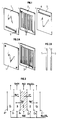
- said membrane comprises appropriate means (channels) (6) allowing the supply of water or saline solution to the separator described below.
- These means can be: a sufficiently porous material allowing an internal flow, rectilinear or sinuous channels (4), spikes and all means making it possible to achieve a spacing between the cationic and anionic membranes situated at the ends of said assembly.
- the anionic membrane (1) can be as described in US Pat. No. 3,705,845 previously cited or as it can be found in the manufacturers of membranes, for example in ASAIII GLASS CO., Or IONICS or TOKUYAMA SODA , or MORGANE.
- Said membrane comprises appropriate means (channels) (5) allowing the evacuation of the separator already described in water or in saline solution.
- each membrane cationic and anionic is associated with a perforated membrane of the same polarity, the respective channels of which cooperate to create the liquid circuit.
- the membrane assembly seen in perspective (fig.2A) and in section (fig.2B) consists of a cationic membrane (3), comprising on one side of the grooves (4) rectilinear or sinuous or any other means known to those skilled in the art for arranging a space between the membranes allowing the circulation of a liquid, this face being placed opposite a full anionic membrane (1).
- the membrane assembly can also be produced by juxtaposition of a solid cationic membrane and an anionic membrane comprising on the opposite face of the cationic membrane grooves or any other means allowing the circulation of a liquid between the two membranes.
- the speed of flow of water or saline solution in the circuit of the anionic and / or cationic membranes can vary in large proportions, it is generally between 0.01 and 1 cm / min. and preferably between 0.2 and 0.6 cm / min.
- the concentration of the solution circulating in the circuit, between the membranes can also vary in great proportions; it can be between 0 (pure water) and the solubility limit of the salt used, it will advantageously be between 0.1 and 3 moles of salts / liter; it may, in certain cases be greater than that of the solution to be electrodialysed, which has the effect of greatly reducing the diffusion of the ions towards the separating compartment and through the membranes and in particular that of the di and trivalent cations, cause of the poisoning of membranes.
- the saline solutions which can be used for carrying out the electrodialysis, with the production of an acid solution and of a basic solution include the solutions of the salts of strong or weak acid with strong or weak bases, said salts having mineral or organic anions , for example the salts containing the anions: Cl ⁇ , SO 2- 4 , SO 2- 3 , PO 3- 4 , NO - 3 , CH3COO ⁇ , C2H5COO ⁇ and mineral or organic cations, such as Na+, NH + 4 , K+ and quaternary ammonium ions (amines for example).
- FIG. (3) gives a representation of an electrodialyzer comprising a single membrane assembly forming the subject of the invention, carrying out the dissociation of water to produce an acid solution and a basic solution from an alkaline salt, for example a solution of Na2SO4.
- an alkaline salt for example a solution of Na2SO4.
- the ions will meet membranes, the cations will be able to cross the cationic membranes but will not be able to cross the anionic membranes, conversely the anions will be able to cross the anionic membranes but will not be able to cross the cationic membranes.
- the current densities generally accepted in such a membrane assembly can be between 10 and 100 mA / cm2 and preferably between 50 and 200 mA / cm2.
- the difference in potential observed on either side of a membrane assembly depends on the current density passing through said assembly; it is generally between 0.9 and 4 volts but will preferably be between 0.9 and 3 volts.
- the compartments E1, B, A, E2 are supplied with a solution of sodium sulphate and the compartment S (or the circuit created on the surface of one of the membranes, in the case of fig. 2) with water and a voltage between the anode A+ and the catode C ⁇ .
- the Na+ ions in compartment E1 move towards the catode, they can cross the cationic membrane C1 and are found in compartment B; OH ⁇ ions from the dissociation of water in compartment S cross the anionic membrane A1 and are found in compartment B where they combine with Na+ ions to form NaOH.
- the Na+ ions from compartment A migrate through the cationic membrane C3 towards the catodic compartment E2.
- the H+ ions from the dissociation of water from compartment S cross the cationic membrane C2 and are found in compartment A and form, with SO4Na2, sodium acid sulfate SO4HNa. Is therefore collected at the outlet of compartment B a basic solution of NaOH and at the outlet of compartment A an acid solution of SO4HNa.
- the number of membrane assemblies can be very large, it can be for example between 1 and 1,000, but preferably between 20 and 200.
- An electrolyser comprising the membrane assembly forming the subject of the present invention is used to generate, from a sodium sulphate solution, a sodium acid sulphate solution and a basic NaOH solution which can be used in an elimination process. sulfur oxides of the fumes. (Simplified diagram in figure (5)).
- Smoke containing SO2 is introduced via line (123) into a washer I where it is brought into contact with a NaOH solution coming from the electrodialyzer III by line (124).
- the purified smoke leaves the washer through the line (125).
- a solution of sodium acid sulfite is collected which is sent via line (126) to a reactor II where it is brought into contact with a solution of SO4HNa originating from the electrodialyzer via line (127).
- sodium acid sulfate On contact with sodium acid sulfate the following chemical reaction takes place: SO3HNa + SO4HNa ⁇ SO2 + SO4Na2 + H2O
- the neutral sodium sulfate produced in reactor II is sent via line (129) to the electrodialyzer III where the separation of the sodium sulfate into NaOH and SO4HNa occurs.
- the washer includes a demister (135) at the top. Water is sent to the head stage via line (136) from a condensate at the rate of 52.96 Kg / h, which is recirculated to stage (132) by the pump (137), and by the line (138).
- a basic solution from the electrodialyzer (139) is sent via line (155) at a rate of 66.45 kg / hr via line (151), the mass composition of which is: NaOH 24.98%, Na2SO4 4.43%, H2O 70.59%, and an addition of NaOH to 20% by weight is brought by line 142 (flow rate 12.24 Kg / h).
- This solution is recirculated around the stage (133) by the pump (140) and the line (141).
- the smoke purified in SO2 and SO3 leaves by the line (143), it has the following volume composition: SO2 0.004%, SO3 0.00008%, No. 71.64%, CO2 14.10%, H2O 12.26%, Where 2%.
- the solution from the reactor (145) is sent via the line (147) to the filter (148) where the or recovers the insoluble products coming from the treated smoke and the washing water (calcium sulphate for example).
- the filtrate is sent, via line (149) and (151), at a rate of 158.65 Kg / h to the electrodialyzer (139) and partly to a purge at a rate of 10.66 Kg / h via the line ( 150), the mass composition of the solution is: SO4Na2 40.86%, H2O 59.13%.
- the acid solution produced is sent via line (146) to the reactor (145) already mentioned.
- the basic solution also produced at the electrodialyzer is sent by the line (151) to the stage of washing of fumes.
- the electrodialyzer consists of 20 membrane cells which are the subject of the invention. Each cell measures 50 cm by 50 cm, the current density is 100 mA / cm2 and the voltage drop of 1.00 volt per cell, the total power supplied to the electrodialyzer, for example I, is 5.325 kilowatts.
- the separators of the electrodialyzer correspond to the first embodiment described, that is to say that the assembly is composed of a first regular cationic membrane, of a second cationic membrane comprising recesses over its entire thickness. allowing the passage of an aqueous solution of salts and a third anionic membrane.
- the thickness of the first cationic membrane is 100 micrometers, that of the membrane comprising the recesses of 100 micrometers, that of the anionic membrane also of 100 micrometers.
- the separators of all the cells are supplied with SO4Na2 solution at 30% by weight, by the line (152) and the pump (154), the outgoing solution is recycled by the line (153) and the pump (154) to the input of the electrodialyzer at the rate of 150 kg / h.
- SO4Na2 solution makes it possible to compensate for the variations in concentration observed during long-term operation. Under these conditions, no reduction in the performance of the electrodialyzer is observed over time.
- An electrodialyzer comprising the membrane assembly forming the subject of the present invention is used to generate, from a solution of sodium acid sulfite originating from a step of washing fumes containing sulfur oxides, an effluent concentrated in SO2 and a solution containing neutral sodium sulfite, solution used in the washing step.
- Figure (7) simplified diagram The electrodialyzer comprising the membrane assembly forming the subject of the present invention is used to generate, from a solution of sodium acid sulfite originating from a step of washing fumes containing sulfur oxides, an effluent concentrated in SO2 and a solution containing neutral sodium sulfite, solution used in the washing step.
- a smoke containing SO2 is introduced via line (201) into a washer I where it is brought into contact with a solution of neutral sodium sulfite, SO3Na2, coming from the electrodialyzer III.
- the purified smoke leaves the washer through the line (202).
- a solution of sodium sulfite acid is collected which is sent via line (203) to the electrodialyzer III.
- the acidic sodium sulfite is separated into SO3Na2 and SO3H2.
- the neutral sodium sulfite solution from the electrodialyzer is sent to the scrubber head via line (206).
- the sulfurous acid solution is drawn off and sent to stripper II where the decomposition of the sulfurous acid solution takes place according to the reaction: SO3H2 ⁇ H2O + SO2 and the pure SO2 is collected at the head, by the line (207), and at the bottom of the water which is recycled to the washer by the line (205) with the SO3Na2 solution from the electrodialyzer.
- the washer includes a demister (305) at the top.
- a top-up water whose flow rate is 35 Kg / h is sent to the head stage via line (306).
- the solution collected on the stage (303) is recirculated to the said stage by the pump (307) and the line (308).
- composition of line (311) is as follows: SO3Na2 37.17%, SO4Na2 4.89%, H2O 57.93%, flow rate of 154.62 Kg / h.
- line (314) NaOH 20%, H2O 80%, debit 12.48 Kg / h.
- the solution collected on the stage tray (304) is recirculated to said stage using the pump (314) and the line (315).
- the solution from the bottom stage of the washer is sent at a rate of 220.8 kg / h by the line (316) to a filter (317) which makes it possible to remove impurities insoluble in the solution (dust collected in the washing step, calcium sulfate), its composition is as follows: SO3HNa 39.07%, SO3Na2 2.36%, SO4Na2 4.67%, SO4Na2 4.72%, H2O 53.85%.
- the filtered solution is sent via line (318) to the electrodialyzer (310) which is the subject of the invention.
- the electrodialyzer (310) under the action of the electric current, the sodium acid sulfite is transformed into neutral sodium sulfite and sulfurous acid according to the reaction: 2SO3HNa + H2O ⁇ SO3Na2 + SO3H2
- two flows are obtained: - a flow of basic solution which is sent to the smoke washing stage via line (311), and - a flow of acid solution, the composition of which is: SO3H2 37.17%; SO4Na2 4.89%; H2O 57.93%. which is sent to the stripper (326) by the line (320).
- the electrolyser (310) is the same as that of the previous example but the voltage at each cell is lower, it is 0.95 volts per cell, which leads to a total power of: 5.058 kilowatts.
- the separator of the electrodialyzer corresponds to the second embodiment described, that is to say that the assembly is composed of a first regular cationic membrane and of a second anionic membrane comprising recesses on only part of the 'thickness, recesses made during the molding of the membrane.
- the thickness of the cationic membrane is 100 micrometers, that of the anionic membrane 200 micrometers.
- the chlorinator (319) is a classic watermaker type chlorinator comprising 20 cells of 50 by 50 cm, the electrical power absorbed is: 1.05 Kilowatt.
Landscapes
- Chemical & Material Sciences (AREA)
- Engineering & Computer Science (AREA)
- Health & Medical Sciences (AREA)
- Manufacturing & Machinery (AREA)
- Water Supply & Treatment (AREA)
- Chemical Kinetics & Catalysis (AREA)
- Inorganic Chemistry (AREA)
- Urology & Nephrology (AREA)
- Materials Engineering (AREA)
- Medicinal Chemistry (AREA)
- Polymers & Plastics (AREA)
- Organic Chemistry (AREA)
- Separation Using Semi-Permeable Membranes (AREA)
Claims (9)
- Membranförmige Anordnung, die eine bipolare Membran bildet, verwendbar insbesondere zur Dissoziation von Waser durch Elektrodialyse, dadurch gekennzeichnet, daß sie im wesentlichena) ein kationisches membranförmiges Element undb) ein anionisches membranförmiges Elementumfaßt, wobei die Elemente miteinander über einen ersten Teil ihrer benachbarten Flächen in Kontakt stehen und über einen zweiten Teil der benachbarten Flächen getrennt sind, derart, um wenigstens einen Durchlaß für die Zirkulation eines Fluids von einer Einlaßöffnung zu einer Auslaßöffnung zu bilden.
- Anordnung nach Anspruch 1, dadurch gekennzeichnet, daß das eine der membranförmigen Elemente eine gleichförmige Oberfläche über die Gesamtheit ihrer in Kontakt stehenden Fläche aufweist und das andere membranförmige Element einen ersten gleichförmigen Teil, der einen ständigen Kontakt mit dem ersten Element sicherstellt, und einen zweiten Teil, der Vertiefungen über nur einen Teil seiner Dicke umfaßt, welche den Durchlaß für ein Fluid bilden, umfaßt.
- Membranförmige Anordnung nach Anspruch 1, dadurch gekennzeichnet, daß das eine (kationische oder anionische) der membranförmigen Elemente durch die Juxtaposition von einer ersten Membran von gleichförmiger und fortgesetzter Oberfläche und von einer zweiten Membran von gleicher Polarität, welche Vertiefungen über die Gesamtheit ihrer Dicke umfaßt, gebildet ist, wobei die Vertiefungen den Durchlaß für ein Fluid bilden, der Kontakt mit dem membranförmigen Element von entgegengesetztem Vorzeichen auf der die Vertiefungen tragenden Membran erfolgt.
- Anordnung nach Anspruch 3, dadurch gekennzeichnet, daß die zwei juxtapositionierten Membranen kationische Membranen sind.
- Anordnung nach Anspruch 3, dadurch gekennzeichnet, daß die zwei juxtapositionierten Membranen anionische Membranen sind.
- Anordnung nach Anspruch 1, dadurch gekennzeichnet, daß die zwei membranförmigen Elemente jeweils durch die Juxtaposition von einer ersten Membran von gleichförmiger und fortgesetzter Oberfläche und von einer zweiten Membran von gleicher Polarität wie die erste Membran, welche Vertiefungen über die Gesamtheit ihrer Dicke umfaßt, gebildet sind, wobei die Vertiefungen des einen membranförmigen Elements mit den Vertiefungen des membranförmigen Elements von entgegensetzter Polarität zusammenwirken, um den Durchlaß zu bilden.
- Anordnung gemäß einem der Ansprüche 3 bis 5, dadurch gekennzeichnet, daß jede Membran Vertiefungen mit einer Tiefe von 50 bis 200 Mikrometern umfaßt.
- Verwendung einer membranförmigen Anordnung gemäß einem der Ansprüche 1 bis 7 in einem elektrochemischen Verfahren, das die Dissoziation von Wasser verwendet, insbesondere in einem Elektrodialyse- oder Elektro-Elektodialyse-Verfahren.
- Verwendung gamäß Anspruch 8, wobei man der Elektrodialyse im Kontakt mit einer membranförmigen Anordnung gemäß einem der Ansprüche 1 bis 7 eine Lösung von Sulfit oder Sulfat von alkalischen Metallen unterwirft, um in getrennten Chargen(a) eine Lösung, deren Konzentration an OH⁻ erhöht ist, und(b) eine Lösung, deren Konzentration an H⁺ erhöht ist, wobei die mit OH⁻ angereicherte Lösung verwendet wird, um das SO₂ des enthaltenen Gases durch Waschung zu eliminieren, und die mit H⁺ angereicherte Lösung verwendet wird, um das SO₂ der Lösung von Sulfiten der alkalischen Metalle oder von organische Kationen besitzenden Sulfiten zu ersetzen,zu erzeugen.
Applications Claiming Priority (2)
| Application Number | Priority Date | Filing Date | Title |
|---|---|---|---|
| FR9011726 | 1990-09-20 | ||
| FR9011726A FR2666998B1 (fr) | 1990-09-20 | 1990-09-20 | Alphassemblage bipolaire de membranes anionique et cationique et son utilisation. |
Publications (2)
| Publication Number | Publication Date |
|---|---|
| EP0477091A1 EP0477091A1 (de) | 1992-03-25 |
| EP0477091B1 true EP0477091B1 (de) | 1995-02-01 |
Family
ID=9400566
Family Applications (1)
| Application Number | Title | Priority Date | Filing Date |
|---|---|---|---|
| EP19910402476 Expired - Lifetime EP0477091B1 (de) | 1990-09-20 | 1991-09-17 | Bipolare Anordnung von anionischen und kationischen Membranen und deren Verwendung |
Country Status (3)
| Country | Link |
|---|---|
| EP (1) | EP0477091B1 (de) |
| DE (1) | DE69107157T2 (de) |
| FR (1) | FR2666998B1 (de) |
Families Citing this family (2)
| Publication number | Priority date | Publication date | Assignee | Title |
|---|---|---|---|---|
| US5961796A (en) * | 1997-06-03 | 1999-10-05 | Lynntech, Inc. | Bipolar membranes with fluid distribution passages |
| DE10332789A1 (de) * | 2003-07-18 | 2005-02-17 | Universität Stuttgart | Membrananordnung, Elektrodialysevorrichtung und Verfahren zur kontinuierlichen elektrodialytischen Entsalzung |
Family Cites Families (2)
| Publication number | Priority date | Publication date | Assignee | Title |
|---|---|---|---|---|
| GB8325479D0 (en) * | 1983-09-23 | 1983-10-26 | Ici Plc | Alkali metal silicates |
| US4766161A (en) * | 1986-06-05 | 1988-08-23 | Allied Corporation | Bipolar membranes and methods of making same |
-
1990
- 1990-09-20 FR FR9011726A patent/FR2666998B1/fr not_active Expired - Lifetime
-
1991
- 1991-09-17 EP EP19910402476 patent/EP0477091B1/de not_active Expired - Lifetime
- 1991-09-17 DE DE1991607157 patent/DE69107157T2/de not_active Expired - Fee Related
Also Published As
| Publication number | Publication date |
|---|---|
| EP0477091A1 (de) | 1992-03-25 |
| FR2666998A1 (fr) | 1992-03-27 |
| DE69107157D1 (de) | 1995-03-16 |
| DE69107157T2 (de) | 1995-06-08 |
| FR2666998B1 (fr) | 1993-07-16 |
Similar Documents
| Publication | Publication Date | Title |
|---|---|---|
| US3686089A (en) | Method of separation of ions from a solution | |
| EP0393843B1 (de) | Trennsysteme mit Hybridmembran | |
| US6149788A (en) | Method and apparatus for preventing scaling in electrodeionization units | |
| US7662267B2 (en) | Device and method for electrodialysis | |
| US6224731B1 (en) | Apparatus and process for electrodialysis of salts | |
| US3964985A (en) | Electrodialysis apparatus and process for ion modification | |
| US4436712A (en) | Method of removing hydrogen sulfide from gases utilizing a polyvalent metal chelate of nitrilotriacetic acid and electrolytically regenerating the solution | |
| US20040079704A1 (en) | Method and apparatus for isolation of ionic species from a liquid | |
| JP2023549031A (ja) | 海洋水からco2を回収するための電気透析装置および電気透析システム | |
| EP0447448B1 (de) | Verfahren zur rückgewinnung von säuren aus sauren und salzhaltigen lösungen | |
| JPH03207487A (ja) | 水精製方法 | |
| US3523755A (en) | Processes for controlling the ph of sulfur dioxide scrubbing system | |
| Liu et al. | Application of bipolar membrane technology: a novel process for control of sulfur dioxide from flue gases | |
| KR960010778B1 (ko) | 황산 티탄 폐기액으로부터 황산을 회수하는 방법 및 장치 | |
| JP3273707B2 (ja) | 電気脱イオン法による脱イオン水の製造法 | |
| US5135626A (en) | Method for purification of bases from materials comprising base and salt | |
| EP0446296B1 (de) | Verfahren zur rückgewinnung von basen aus basen- und salzhaltigen lösungen | |
| EP0477091B1 (de) | Bipolare Anordnung von anionischen und kationischen Membranen und deren Verwendung | |
| CA1272982A (en) | Method for the recovery of lithium from solutions by electrodialysis | |
| US4786386A (en) | Process and apparatus for the treatment of water and effluents by ultra-filtration and electrolysis | |
| US4758319A (en) | Dialyzing crossflow electrofilter with improved electrode | |
| US3974258A (en) | Process for purifying a sulfur dioxide containing gas | |
| US5064538A (en) | Membrane process for acid recovery | |
| EP0039410A1 (de) | Konzentrierung von Alkalimetall-Hydroxid | |
| JP7163274B2 (ja) | ヨウ素系物質の取得方法 |
Legal Events
| Date | Code | Title | Description |
|---|---|---|---|
| PUAI | Public reference made under article 153(3) epc to a published international application that has entered the european phase |
Free format text: ORIGINAL CODE: 0009012 |
|
| AK | Designated contracting states |
Kind code of ref document: A1 Designated state(s): BE DE GB IT NL |
|
| 17P | Request for examination filed |
Effective date: 19920727 |
|
| 17Q | First examination report despatched |
Effective date: 19940325 |
|
| ITF | It: translation for a ep patent filed | ||
| GRAA | (expected) grant |
Free format text: ORIGINAL CODE: 0009210 |
|
| AK | Designated contracting states |
Kind code of ref document: B1 Designated state(s): BE DE GB IT NL |
|
| REF | Corresponds to: |
Ref document number: 69107157 Country of ref document: DE Date of ref document: 19950316 |
|
| GBT | Gb: translation of ep patent filed (gb section 77(6)(a)/1977) |
Effective date: 19950313 |
|
| PLBE | No opposition filed within time limit |
Free format text: ORIGINAL CODE: 0009261 |
|
| STAA | Information on the status of an ep patent application or granted ep patent |
Free format text: STATUS: NO OPPOSITION FILED WITHIN TIME LIMIT |
|
| 26N | No opposition filed | ||
| PGFP | Annual fee paid to national office [announced via postgrant information from national office to epo] |
Ref country code: BE Payment date: 20010924 Year of fee payment: 11 |
|
| PGFP | Annual fee paid to national office [announced via postgrant information from national office to epo] |
Ref country code: DE Payment date: 20011011 Year of fee payment: 11 |
|
| REG | Reference to a national code |
Ref country code: GB Ref legal event code: IF02 |
|
| PGFP | Annual fee paid to national office [announced via postgrant information from national office to epo] |
Ref country code: GB Payment date: 20020823 Year of fee payment: 12 |
|
| PG25 | Lapsed in a contracting state [announced via postgrant information from national office to epo] |
Ref country code: BE Free format text: LAPSE BECAUSE OF NON-PAYMENT OF DUE FEES Effective date: 20020930 |
|
| PGFP | Annual fee paid to national office [announced via postgrant information from national office to epo] |
Ref country code: NL Payment date: 20020930 Year of fee payment: 12 |
|
| BERE | Be: lapsed |
Owner name: INSTITUT FRANCAIS DU *PETROLE Effective date: 20020930 |
|
| PG25 | Lapsed in a contracting state [announced via postgrant information from national office to epo] |
Ref country code: DE Free format text: LAPSE BECAUSE OF NON-PAYMENT OF DUE FEES Effective date: 20030401 |
|
| PG25 | Lapsed in a contracting state [announced via postgrant information from national office to epo] |
Ref country code: GB Free format text: LAPSE BECAUSE OF NON-PAYMENT OF DUE FEES Effective date: 20030917 |
|
| PG25 | Lapsed in a contracting state [announced via postgrant information from national office to epo] |
Ref country code: NL Free format text: LAPSE BECAUSE OF NON-PAYMENT OF DUE FEES Effective date: 20040401 |
|
| GBPC | Gb: european patent ceased through non-payment of renewal fee |
Effective date: 20030917 |
|
| NLV4 | Nl: lapsed or anulled due to non-payment of the annual fee |
Effective date: 20040401 |
|
| PG25 | Lapsed in a contracting state [announced via postgrant information from national office to epo] |
Ref country code: IT Free format text: LAPSE BECAUSE OF NON-PAYMENT OF DUE FEES;WARNING: LAPSES OF ITALIAN PATENTS WITH EFFECTIVE DATE BEFORE 2007 MAY HAVE OCCURRED AT ANY TIME BEFORE 2007. THE CORRECT EFFECTIVE DATE MAY BE DIFFERENT FROM THE ONE RECORDED. Effective date: 20050917 |