EP0475624A1 - Bibliothèque de mémoire automatisée - Google Patents
Bibliothèque de mémoire automatisée Download PDFInfo
- Publication number
- EP0475624A1 EP0475624A1 EP91307830A EP91307830A EP0475624A1 EP 0475624 A1 EP0475624 A1 EP 0475624A1 EP 91307830 A EP91307830 A EP 91307830A EP 91307830 A EP91307830 A EP 91307830A EP 0475624 A1 EP0475624 A1 EP 0475624A1
- Authority
- EP
- European Patent Office
- Prior art keywords
- library
- optical disk
- scsi
- bus
- coupled
- Prior art date
- Legal status (The legal status is an assumption and is not a legal conclusion. Google has not performed a legal analysis and makes no representation as to the accuracy of the status listed.)
- Withdrawn
Links
- 230000002093 peripheral effect Effects 0.000 claims description 21
- 238000013500 data storage Methods 0.000 claims description 9
- 238000012545 processing Methods 0.000 claims description 6
- 238000012546 transfer Methods 0.000 claims description 6
- 230000008878 coupling Effects 0.000 claims description 5
- 238000010168 coupling process Methods 0.000 claims description 5
- 238000005859 coupling reaction Methods 0.000 claims description 5
- 230000003287 optical effect Effects 0.000 abstract description 85
- 239000003999 initiator Substances 0.000 description 15
- 210000000352 storage cell Anatomy 0.000 description 9
- 230000002457 bidirectional effect Effects 0.000 description 8
- 238000004891 communication Methods 0.000 description 4
- 238000010586 diagram Methods 0.000 description 3
- 238000012986 modification Methods 0.000 description 3
- 230000004048 modification Effects 0.000 description 3
- 230000009471 action Effects 0.000 description 2
- 210000004027 cell Anatomy 0.000 description 2
- 230000003111 delayed effect Effects 0.000 description 2
- 238000013461 design Methods 0.000 description 2
- 210000004556 brain Anatomy 0.000 description 1
- 239000003990 capacitor Substances 0.000 description 1
- 238000011161 development Methods 0.000 description 1
- 230000000694 effects Effects 0.000 description 1
- 230000006870 function Effects 0.000 description 1
- 238000003780 insertion Methods 0.000 description 1
- 230000037431 insertion Effects 0.000 description 1
- 238000000034 method Methods 0.000 description 1
- 230000037361 pathway Effects 0.000 description 1
- 230000000704 physical effect Effects 0.000 description 1
- 239000007787 solid Substances 0.000 description 1
- 230000001360 synchronised effect Effects 0.000 description 1
Images


Classifications
-
- G—PHYSICS
- G06—COMPUTING; CALCULATING OR COUNTING
- G06F—ELECTRIC DIGITAL DATA PROCESSING
- G06F11/00—Error detection; Error correction; Monitoring
- G06F11/07—Responding to the occurrence of a fault, e.g. fault tolerance
- G06F11/16—Error detection or correction of the data by redundancy in hardware
- G06F11/20—Error detection or correction of the data by redundancy in hardware using active fault-masking, e.g. by switching out faulty elements or by switching in spare elements
- G06F11/2002—Error detection or correction of the data by redundancy in hardware using active fault-masking, e.g. by switching out faulty elements or by switching in spare elements where interconnections or communication control functionality are redundant
- G06F11/2007—Error detection or correction of the data by redundancy in hardware using active fault-masking, e.g. by switching out faulty elements or by switching in spare elements where interconnections or communication control functionality are redundant using redundant communication media
-
- G—PHYSICS
- G06—COMPUTING; CALCULATING OR COUNTING
- G06F—ELECTRIC DIGITAL DATA PROCESSING
- G06F11/00—Error detection; Error correction; Monitoring
- G06F11/07—Responding to the occurrence of a fault, e.g. fault tolerance
- G06F11/16—Error detection or correction of the data by redundancy in hardware
- G06F11/20—Error detection or correction of the data by redundancy in hardware using active fault-masking, e.g. by switching out faulty elements or by switching in spare elements
- G06F11/2053—Error detection or correction of the data by redundancy in hardware using active fault-masking, e.g. by switching out faulty elements or by switching in spare elements where persistent mass storage functionality or persistent mass storage control functionality is redundant
- G06F11/2089—Redundant storage control functionality
-
- G—PHYSICS
- G06—COMPUTING; CALCULATING OR COUNTING
- G06K—GRAPHICAL DATA READING; PRESENTATION OF DATA; RECORD CARRIERS; HANDLING RECORD CARRIERS
- G06K17/00—Methods or arrangements for effecting co-operative working between equipments covered by two or more of main groups G06K1/00 - G06K15/00, e.g. automatic card files incorporating conveying and reading operations
- G06K17/0003—Automatic card files incorporating selecting, conveying and possibly reading and/or writing operations
- G06K17/0012—Automatic card files incorporating selecting, conveying and possibly reading and/or writing operations with more than one selection steps, e.g. selection of a record carrier from a selected compartment of a compartmented storage
-
- G—PHYSICS
- G11—INFORMATION STORAGE
- G11B—INFORMATION STORAGE BASED ON RELATIVE MOVEMENT BETWEEN RECORD CARRIER AND TRANSDUCER
- G11B17/00—Guiding record carriers not specifically of filamentary or web form, or of supports therefor
- G11B17/22—Guiding record carriers not specifically of filamentary or web form, or of supports therefor from random access magazine of disc records
- G11B17/225—Guiding record carriers not specifically of filamentary or web form, or of supports therefor from random access magazine of disc records wherein the disks are transferred from a fixed magazine to a fixed playing unit using a moving carriage
-
- G—PHYSICS
- G11—INFORMATION STORAGE
- G11B—INFORMATION STORAGE BASED ON RELATIVE MOVEMENT BETWEEN RECORD CARRIER AND TRANSDUCER
- G11B27/00—Editing; Indexing; Addressing; Timing or synchronising; Monitoring; Measuring tape travel
- G11B27/002—Programmed access in sequence to a plurality of record carriers or indexed parts, e.g. tracks, thereof, e.g. for editing
-
- G—PHYSICS
- G11—INFORMATION STORAGE
- G11B—INFORMATION STORAGE BASED ON RELATIVE MOVEMENT BETWEEN RECORD CARRIER AND TRANSDUCER
- G11B2220/00—Record carriers by type
- G11B2220/20—Disc-shaped record carriers
-
- G—PHYSICS
- G11—INFORMATION STORAGE
- G11B—INFORMATION STORAGE BASED ON RELATIVE MOVEMENT BETWEEN RECORD CARRIER AND TRANSDUCER
- G11B2220/00—Record carriers by type
- G11B2220/40—Combinations of multiple record carriers
- G11B2220/41—Flat as opposed to hierarchical combination, e.g. library of tapes or discs, CD changer, or groups of record carriers that together store one title
-
- G—PHYSICS
- G11—INFORMATION STORAGE
- G11B—INFORMATION STORAGE BASED ON RELATIVE MOVEMENT BETWEEN RECORD CARRIER AND TRANSDUCER
- G11B27/00—Editing; Indexing; Addressing; Timing or synchronising; Monitoring; Measuring tape travel
- G11B27/10—Indexing; Addressing; Timing or synchronising; Measuring tape travel
- G11B27/34—Indicating arrangements
-
- G—PHYSICS
- G11—INFORMATION STORAGE
- G11B—INFORMATION STORAGE BASED ON RELATIVE MOVEMENT BETWEEN RECORD CARRIER AND TRANSDUCER
- G11B27/00—Editing; Indexing; Addressing; Timing or synchronising; Monitoring; Measuring tape travel
- G11B27/36—Monitoring, i.e. supervising the progress of recording or reproducing
Definitions
- the present invention relates to an automated storage library having a redundant SCSI bus system. More particularly, the present invention is an automated storage library having a redundant SCSI bus system permitting switching among paths between library controllers, pickers, and peripheral storage devices should one path become disabled.
- the main components of a computer system include host processors, input/output (I/O) devices, and storage.
- Processors are the brain of computer systems, performing arithmetic and logical operations. I/O devices permit data to be input to or output from the system.
- a keyboard is an example of an input device and a printer is an example of an output device.
- Storage includes means for temporarily and permanently storing information, including user data and the instructions which direct computer operations. Storage may be within a processor, such as integrated circuit main memory, or may be peripheral thereto, such as magnetic disks, magnetic tapes, and optical disks.
- a machine used to write to and read from such peripheral storage is known as a peripheral storage device and typically includes a device controller for translating processor commands into the physical actions of the device itself.
- Each of the computer system components may be divided into subcomponents and may be distributed across various locations within the computer system.
- a bus The set of wires, paths, or connections for carrying signals throughout a computer system is known as a "bus". These internal pathways for information signals may also be subdivided.
- a computer system may include a data bus, control bus and address bus.
- a particular set of communication signal protocols is typically used on a bus, depending upon such factors as the computer system components, the configuration of such components, and the bus pathing scheme. Many bus schemes are therefore customized to meet the needs of a particular computer system.
- the addition of a new type of peripheral storage device to the system thus also requires the addition of hardware and/or software to teach the processor how to communicate with such new device.
- SCSI is a specification for a bidirectional, peripheral storage device bus and command set.
- the specification defines a high performance interface that distributes data among peripherals independently of a host processor.
- a SCSI bus provides a computer system with storage device independence within a class of devices, such as disk drives or tape drives. Different devices within a particular class can thus be added to a computer system without major modification of the system hardware or software.
- Adapter cards and SCSI protocol chips are used to connect processors to a SCSI bus scheme. Such chips and cards are available from numerous vendors to support SCSI bus schemes for common computer systems (e.g. IBM personal computers and machines compatible therewith). The chips and cards may be custom designed, but are much smaller and easier to design than a complete computer system, and may themselves be standardized as field replaceable units for particular systems.
- Multiple bus schemes are sometimes referred to as multiple buses, or as a single bus having multiple paths. Multiple paths between two system components allows for communication therebetween despite the failure or busy status of one of such paths.
- Some redundant bus schemes are designed to improve system operating speeds by dynamically switching between multiple paths during normal (i.e. no failed components) system operations. Because of their dynamic nature, these bus schemes tend to be quite complex and are thus not practical in many applications. Other bus schemes are designed merely to maintain the availability of data despite certain component failures. Such redundant bus schemes typically rely on a primary bus to carry communications between any two particular components, and a secondary bus which can be switched into use should the primary bus fail.
- redundant storage libraries such as the combination of the IBM 3990 Storage Control Unit and the IBM 3380 Direct Access Storage Device
- redundant storage libraries use either two oppositely flowing unidirectional buses, or a single bidirectional bus which is customized to accommodate such bidirectionality.
- a redundant SCSI bus system is disclosed in US Patent 4,821,170.
- the patent discloses an I/O system for a plurality of host processors and a plurality of I/O devices in which ownership of the processor I/O channels is shared.
- the bus scheme includes two strings of SCSI peripheral devices which are connected at each end to either of two switches each embedded in and controlled by a different SCSI protocol chip, thereby forming a loop (i.e. the strings are double-ended).
- Each SCSI protocol chip is itself mounted on the adapter card of a different one of two device controllers. Because each switch is embedded in an adapter card, the adapter card itself is customized.
- the adapter cards/switches are customized to accommodate the passage of information in addition to that otherwise passed to and from a switch in a SCSI bus scheme.
- the switch control logic lines are connected directly to the adapter cards, thereby allowing the adapter cards to signal the switches active only for the precise transaction desired.
- the adapter card senses the completion of a transaction across a switch and can then deactivate such switch to prevent latching of the switch.
- Such a smart adapter card/switch allows for the bus scheme to perform certain tasks such as concurrent access to two devices (one per string), but at the expense of requiring customized parts.
- An automated storage library is a subsystem including one or more peripheral storage devices (i.e. a storage library), a set of storage cells for maintaining a library of peripheral data storage media, and a robotic picker capable of transferring such media therebetween upon command (i.e. to automate the storage library).
- the picker is capable of inserting a data storage medium into or removing a data storage medium from a storage cell or a peripheral storage device within the subsystem.
- An automated storage library thus provides for a massive amount of data to be maintained accessible to a processor without manual assistance and is used most frequently in large computer systems because only those systems require such amounts of storage.
- One automated storage library that does use a SCSI bus system is the IBM 9246 Optical Disk Library.
- the library includes two separate controllers, each attached only to a separate string of optical disk drives by different SCSI buses. No bus redundancy is achieved to the optical disk drives.
- a single picker is used to service both device strings. The single picker is not treated as a SCSI device and thus is not coupled to a SCSI bus. Instead, thy picker is connected to the library controller using a different bus and protocol, resulting in increased system complexity. Finally, no provisions are made for coupling additional library controllers or pickers to the bus scheme.
- the present invention provides a data processing system including an automated storage library, said automated storage library comprising one or more data storage media; one or more peripheral devices for transferring data between said automated storage library and said data processing system; one or more cells for housing said data storage media; a picker for transferring one of said storage media between one of said cells and one of said peripheral devices; a first and second library controller, each for instructing said picker to transfer data storage media and for controlling data transfer in said peripheral device or devices; and a switch having a first and second side, said first and second library controllers coupled to said first side of said switch and said picker and peripheral device or devices coupled to said second side of said switch whereby said switch permits switching between said first and second library controllers thereby allowing said automated storage library to operate when a failure in said automated storage library renders operation by means of one of said library controllers not possible.
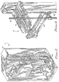
- the automated storage library will be described as embodied in an optical disk library. Referring to Figs. 1 - 4, various views of such an optical disk library are shown.
- the library 1 includes a housing 2 enclosing most of the working parts of the library and having front and rear door panels (not shown) for interior access.
- Library 1 further includes a plurality of optical disk storage cells 3 and a plurality of internal optical disk drives 4.
- Each storage cell 3 is capable of storing one optical disk having data recorded on one or both sides thereof. The data stored on each side of a disk is referred to as a "volume".
- library 1 includes one hundred and forty four storage cells 3 arranged in two 72 storage cell columns and up to four optical disk drives 4.
- the optical disks may include ablative, phase-change, magneto-optic, or any other optical recording layers and may be read-only, write-once, or rewritable, so long as they are compatible with optical disk drive 4.
- the optical disks may be recorded in a spiral or concentric track pattern.
- a robotic picker 5 includes a single gripper 6 capable of accessing an optical disk in any of storage cells 3 or drives 4 and transferring such optical disks there-between.
- the optical disks are configured in cartridges for easy handling by gripper 6 and are 5 and 1/4 inch form factor disks, but in alternative embodiments could be any size compatible with drives 4 and gripper 6.
- console door 7 Although the front face of housing 2 is not shown in Fig. 1, certain portions of library 1 protrude through such front face of housing 2 for operator access. These portions are part of a console door 7 and include all or part of a power indicator/switch 8, an entry/exit slot 9, an external optical disk drive 10, a console 11, and a keyboard 12. Console door 7 can be swung aside to allow access therebehind, when necessary, as shown in Fig. 2. Slot 9 is used for inserting optical disks to or removing optical disks from library 1.
- Commands may be provided by an operator to library 1, via keyboard 12, to have picker 5 receive an optical disk inserted at slot 9 and transport such disk to a storage cell 3 or drive 4, or to have picker 5 retrieve an optical disk from a storage cell 3 or drive 4 and deliver such disk to slot 9 for removal from library 1.
- Console 11 allows an operator to monitor and control certain operations of library 1 without seeing inside housing 2. External optical disk drive 10, unlike drives 4, cannot be accessed by gripper 6. Drive 10 must instead be loaded and unloaded manually.
- Library 1 also includes an optical disk drive exhaust fan 14, an external disk drive exhaust fan 15, and power supplies 16.
- library controller 17 is an IBM PS/2 Model 80 personal computer using the OS/2 operating system.
- the IBM PS/2 model 80 personal computer includes main memory and one or more storage media, such as those in fixed or floppy disk drives.
- Library controller 17 issues instructions to drives 4, external drive 10, and picker 5 as will be described.
- Drive controller cards 13 and picker 5 controller card 18 convert known small computer system interface (SCSI) command packets issued by library controller 17 into the electromechanical action of drives 4, external drive 10, and picker 5.
- SCSI small computer system interface
- a double-sided, multi-ported switch 60 is included in library 1 and will be further described later therein.
- the movement of picker 5 within library 1 is X-Y in nature.
- Movement in the vertical direction is driven by a vertical direction motor 19 and movement in the horizontal direction is driven by a horizontal direction motor 20.
- Motor 19 turns a lead screw 21 to move picker 5 vertically.
- Motor 20 turns belts 22 and 23 to move picker 5 horizontally.
- picker 5 may be rotated to bring either side of an optical disk within the grasp of gripper 6 to an upright position.
- the remaining physical features of library 1 are not shown in the drawing, or are shown but not labeled for the purpose of simplification.
- the library shown in Figs. 1 - 4 is a simple single box (a self-contained, free standing unit) library configuration. Although a SCSI bus is used, no redundancy is provided as the system is relatively small. Various other library configurations are known. In the preferred embodiment, four such boxes are interconnected with some modification (as will be described) to create a library of greater storage capacity and flexibility. Referring to Fig. 5, such four box configuration library will now be described. The four boxes are schematically divided by dotted lines and are identified by numerals 1A, 1B, 1a and 1b. Boxes 1A and 1a each include a library controller, identified as 17A and 17a respectively.
- Boxes 1B and 1b include no library controller, instead being coupled to library controllers 17A and 17a. Further description of library controller 17 can be found in commonly assigned US patent application serial number 07/526256 (docket TU9-89-027) filed May 21, 1990, hereby incorporated by reference.
- One important feature of the library controllers is the use of the IBM PS/2 Model 80 personal computer, as previously mentioned, because it is a commonly available component.
- the PS/2 Model 80 personal computer includes eight expansion slots to the motherboard therein. Four of such expansion slots are used by console 11, expanded memory and standard subcomponents of the personal computer. The remaining four expansion slots are available for coupling to the components of the library.
- Library controllers 17A and 17a are attached to one or more system processors 30 to receive input therefrom and to transmit output thereto.
- system processor 30 is an IBM 3090 mainframe processor using the MVS or VM operating system, the connections to which are well known. Other system processors and operating systems could also be used.
- Library controllers 17A and 17a are connected to each other by the well known RS-232 interface 31 and are each capable of accessing any optical disk stored in any box in the library. Normally, one library controller (sometimes referred to as the "primary" library controller) directs the operation of two boxes and the other library controller directs the operation of the other two boxes.
- library controller 17A is the primary library controller for boxes 1A and 1B and library controller 17a is the primary library controller for boxes 1a and 1b.
- library controller 17A can signal the other (secondary) library controller using the RS-232 interface 31. The primary library controller then ceases operation and the secondary library controller attempts access of the desired optical disk.
- Library controllers 17A and 17a each include four SCSI adapter cards, one in each of the available expansion slots therein.
- the SCSI adapters are identified in the drawing as 41-48 and are commonly available.
- Each adapter card is coupled by one of SCSI buses 51-58 to other components of the library as shown including sixteen internal optical disk drives 4A, 4B, 4a and 4b, four robotic pickers 5A, 5B, 5a and 5b, four external optical disk drives 10A, 10B, 10a and 10b, and four bidirectional, double-sided, multi-ported switches 60A, 60B, 60a and 60b.
- a SCSI bus is used because it can provide the use of logical addressing for all data, the bidirectional passage of information, the constraint of supporting no more than eight SCSI devices using a limited cable length (6 meters for the single-ended version), the constraint that all such SCSI devices include provisions for signal termination, and the use of fifty lines, eighteen signals and eight phases of bus activity. Of the eight SCSI devices that can be attached to the bus, only one pair of such devices can communicate to any particular time.
- the sending/originating device is referred to as the initiator and the receiving/-responding (by performing a requested operation) device is referred to as the target.
- the bus protocol provides for the connection of multiple initiators and targets.
- SCSI devices have a fixed role as an initiator or a target, but some devices are able to assume either role.
- any of SCSI adapter cards 41-48, internal optical disk drives, 4A, 4B, 4a and 4b, pickers 5A, 5B, 5a and 5b, and external optical disk drives 10A, 10B, 10a and 10b may be an initiator or a target.
- SCSI signal termination is required to set the impedance of lines to prevent the reflection of signals after a time delay. Without such termination, the predictability of voltage levels on the lines is lost. SCSI terminators will be described further with reference to Fig. 7.
- control signals are used to determine when and in what direction data is transferred.
- These signals include attention (ATN - used by an initiator to inform a target that it has a message), busy (BSY - used by an initiator or target to declare the bus busy), acknowledge (ACK - used by the initiator to acknowledge a request from a target), reset (RST - used by an initiator or target to reset the bus), message (MSG - used by a target to inform an initiator that a message is being transferred), select (SEL - used by an initiator to select a target and by a target to reselect an initiator), control/data (C/D - used by a target to indicate whether information is control information or data), request (REQ - used by the target to request a data transfer), and input/output (I/O - used by the target to define the direction of movement on the bus).
- the data signals include command, status,
- the bus phases determine what type of information is on the data lines and the direction of information movement.
- the bus can never be in more than one phase at any given time.
- the eight bus phases are determined by the control signals and include bus free, arbitration, selection, reselection, command, data, status, and message.
- the bus free phase indicates that no SCSI device is currently using the SCSI bus (i.e. the bus is available for use).
- the arbitration phase is optional and allows one SCSI device to gain control of the SCSI bus.
- the selection phase allows an initiator to choose a target.
- the reselection phase is optional and allows a target to reconnect to an initiator to complete a suspended operation.
- the command, data, status, and message phases are used to transfer the respective type of information on the SCSI bus.
- the command phase allows tie target to request command information from the initiator.
- the data phase allows the target to request that data be sent on the SCSI bus.
- the status phase allows the target to request to send status information to an initiator.
- the message phase allows the target to request that a message be sent on the SCSI bus.
- SCSI bus protocol A further description of the SCSI bus protocol, signals, phases, and other aspects of operation can be found in American National Standards Institute (ANSI) Small Computer Systems Interface (SCSI) specification X3.131-1986, available from ANSI, 1430 Broadway, New York, New York 10018, and SCSI, "Understanding the Small Computer System Interface", Copyright 1990 by NCR Corporation, and available from Prentice-Hall Inc., Inglewood Cliffs, New Jersey 07632. Except, as provided herein, the SCSI bus system of the present invention operates according to the single-ended driver/receiver SCSI standard using either asynchronous or synchronous protocol.
- ANSI American National Standards Institute
- SCSI Small Computer Systems Interface
- Switches 60A, 60B, 60a and 60b are capable of directing information exchange between any path coupled to one side of the switch and any path coupled to the other side of the switch.
- the switch sides are not identified by numerals in the drawing, but are separated by a solid horizontal line in Fig. 5.
- the switches are double-sided and multi-ported in that both sides thereof include at least two ports for connecting separate paths of SCSI bus 50.
- the switches are not physically included in the circuitry of SCSI adapters 41-48, internal optical disk drives 4A, 4B, 4a and 4b, or pickers 5A, 5B, 5a and 5b - but are located out on the SCSI buses, thereby eliminating the need for customized SCSI adapters or device controllers.
- the switches although customized in themselves, are thus single field replaceable units. The switches will be described further herein with reference to Figs. 6 - 7.
- the internal optical disk drives, pickers, and external optical disk drives are connected in such manner as to enhance both the availability of data in the library and the expandability of the library.
- the availability of data depends on the points of failure in the library, such as at the drive or picker level, the switch level, the SCSI adapter level, the library controller level, or above. Any single point of failure could potentially disable a SCSI bus 51-58 and eliminate the operation of certain components coupled at that level or below.
- the failure of an internal optical disk drive eliminates access to it and potentially to all other optical disk drives attached to the same device string.
- a two device, single-ended (i.e. only one end is attached to a SCSI adapter) device string 49 is identified in the drawing as an example and is actually part of SCSI bus 51 or SCSI bus 55 depending upon the position of switch 60B.
- Internal optical disk drives 4A, 4B, 4a and 4b are arranged on two single-ended strings coupled to the switches in each box to prevent the failure of any single internal optical disk drive therein from eliminating access to all such internal optical disk drives in a box (as if, for example, all four internal optical disk drives in a box were arranged on one single-ended string of devices). For a greater measure of safety, the internal optical disk drives could be individually arranged on separate single device single-ended strings.
- pickers 5A, 5B, 5a and 5b are arranged on single-ended device strings apart from any optical disk drives. The picker is a critical component of the library as optical disks in a box cannot be accessed without operation of the picker unless they by chance are already mounted in an optical disk drive.
- a picker is arranged in a device string with an optical disk drive, the failure of such optical disk drive could disable the bus 50 and eliminate operation of the picker.
- library controller 17A or 17a has at least one internal optical disk drive and a picker in the same box available, access to any optical disk in a box is possible, although at potentially reduced performance.
- box 1A is coupled to SCSI adapter 42 by SCSI bus 52 and box 1B is coupled to SCSI adapter 41 by SCSI bus 51. This prevents access to either box from being lost by a failure in the other box. Only a failure in library controller 17A (or above) would eliminate the access to both boxes by library controller 17A.
- SCSI adapter 45 and SCSI bus 55 couple library controller 17a to boxes 1A and 1B, and because switches 60A and 60B prevent failures in library controller 17A from effecting the operation of the SCSI devices coupled to the other sides of switches 60A and 60B (as will be described), the optical disks therein could still be accessed by switching library operations from library controller 17A to library controller 17a, as previously described.
- SCSI buses 51, 52, 57 and 58 are each coupled to six SCSI devices, including SCSI adapters 41, 42, 47 and 48 respectively. This permits the addition of one or two SCSI devices, such as internal optical disk drives, to a box if desired.
- SCSI buses 54 and 55 are potentially coupled to eleven SCSI devices, including SCSI adapters 44 and 45, respectively.
- each library controller is programmed to address less than all of the internal optical disk drives coupled to SCSI bus 54 and 55.
- SCSI adapter 44 only addresses one single-ended string of internal optical disk drives 4a in box 1a and one single-ended string of internal optical disk drives 4b in box 4b (and also pickers 5a and 5b, respectively, for a total of seven SCSI devices on SCSI bus 54 including SCSI adapter 44 itself). This is accomplished by microcode-controlled addressing and switch position selection techniques.
- the two remaining SCSI adapters 43 and 46 are coupled via buses 53 and 56 to external optical disk drives 10A and 10B, and external optical disk drives 10a and 10b respectively.
- Such coupling isolates the external optical disk drives from the pickers, internal optical disk drives, and switches of each box to maintain a certain minimum level of data availability. Even when access to all optical disks inside of a box is lost, optical disks outside of the library may still be accessed by their manual insertion into the external optical disk drive.
- the external optical disk drives could instead be coupled to the same SCSI bus as their respective internal optical disk drives, allowing for a different one of the SCSI adapters in each library controller to be coupled to a different box.
- each box includes six SCSI devices, not including the SCSI adapters, it is impossible to couple and support all of the SCSI devices in two such boxes to/on a single SCSI bus.
- the number of external optical disk drives coupled to SCSI buses 53 and 56 could be expanded as desired so long as the number of SCSI devices supported by a single SCSI bus does not exceed eight.
- the switch includes transceivers 70 and 71 on one side and transceivers 80-82 on the other side.
- the transceivers serve to receive and transmit signals across the switch.
- Transceivers 70 and 71 are each coupled by a SCSI bus to one of the library controllers and transceivers 80-82 are each coupled to one single-ended device string.
- Anti-latch and control logic circuits 61 provide two functions.
- the anti-latch circuits prevent latch conditions that would otherwise occur because of positive feedback in the transceiver circuits.
- the control logic circuits allow either of transceivers 70 and 71 to be coupled to any one or more of transceivers 80-82 at any given time.
- the transceivers selected at any particular time are continuously active.
- the number of transceivers on either side of the switches could be modified to accommodate different SCSI bus and SCSI device configurations.
- Each transceiver includes a bidirectional inverter driver/-receiver.
- An AND gate serves as the driver/transmitter and a Schmitt trigger/-inverter serves as the receiver for each transceiver.
- Transceivers 80-82 also include one diode each to isolate the receivers from each other.
- Each transceiver is terminated according to SCSI specifications using a 220 ohm and a 330 ohm resistor arranged as a voltage divider.
- the control logic circuits 61a are common to all SCSI signals in the library, coupling the library controller parallel port (not the SCSI adapters) to the switches to allow for control of the position of the switches. Select lines are coupled to library controllers 17A and 17a respectively to manipulate control logic circuits 61a.
- the anti-latch circuits 61b includes two 100 ohm resistors, two 150 picofarad capacitors, and two exclusive OR gates. The anti-latch circuits prevent positive feedback among the transceivers. For example, consider the situation where control logic circuits 61a are set to allow communication between transceivers 70 and 82, and a signal is to be transferred from transceiver 70 to transceiver 82.
- an active low signal When an active low signal is present at the receiver of transceiver 70 it is inverted and sent to the upper XOR gate (as shown) in anti-latch circuits 61b. Remaining inverted, the signal is sent to the driver of transceiver 82 and is also delayed by an RC network and sent to the lower XOR gate of anti-latch circuits 61b. The driver of the transceiver 82 inverts the signal back to a low state, which is then inverted high by the receiver of transceiver 82 and sent to the other input of the lower XOR gate of anti-latch circuits 61b.
- this high signal would be sent back to the driver of transceiver 70, which would then hold the input to the receiver of transceiver 70 low even after the low signal from the SCSI bus is removed.
- This latching action is prevented by applying the delayed signal from the upper XOR gate to the lower XOR gate of anti-latch circuits 61b, when the low signal from the SCSI bus is removed from the receiver of transceiver 70, the driver of transceiver 82 no longer drives the SCSI bus line or the receiver of transceiver 82 low.
- the automated storage library has a redundant SCSI bus system which minimizes the need for customized subcomponents.
- the automated storage library has a redundant SCSI bus system which couples the picker to the SCSI bus.
- the optical disk library described has a redundant SCSI bus system which utilizes double-sided, multi-ported switches for connecting each of two library controllers to all library pickers and some or all of the optical disk drives in the library.
- the use of additional library controllers and pickers allows for greater subsystem flexibility and redundancy.
- the double-sided, multi-ported switches minimize the need for additional SCSI adapters to the library controllers and include anti-latch circuitry between sets of transceivers to eliminate the need to customize the SCSI adapters.
- the switches are continuously active, yet do not latch, and allow the bus system to meet the constraints of the SCSI standard - including bidirectional capability, maximum number of supported devices, and limited cable length.
- the switches are physically located apart from the SCSI adapters, pickers, and optical disk drives, thereby improving field replaceable unit maintainability, and permit switching from the primary library controller to the secondary library controller to provide access to any optical disk in the library when a failure in the system has otherwise made such optical disk inaccessible through the primary library controller.
- the pickers and optical disk drives are coupled to the switches in one or more single-ended strings to simplify library operations and minimize the amount of the library made inoperative by a device failure. Each picker is coupled to the switches on a single-ended string to which no optical disk drive is attached, further reducing the likelikhood that access to optical disks in the library will be lost during a failure.
Applications Claiming Priority (2)
| Application Number | Priority Date | Filing Date | Title |
|---|---|---|---|
| US07/579,505 US5289589A (en) | 1990-09-10 | 1990-09-10 | Automated storage library having redundant SCSI bus system |
| US579505 | 1990-09-10 |
Publications (1)
| Publication Number | Publication Date |
|---|---|
| EP0475624A1 true EP0475624A1 (fr) | 1992-03-18 |
Family
ID=24317163
Family Applications (1)
| Application Number | Title | Priority Date | Filing Date |
|---|---|---|---|
| EP91307830A Withdrawn EP0475624A1 (fr) | 1990-09-10 | 1991-08-27 | Bibliothèque de mémoire automatisée |
Country Status (3)
| Country | Link |
|---|---|
| US (1) | US5289589A (fr) |
| EP (1) | EP0475624A1 (fr) |
| JP (1) | JPH0743681B2 (fr) |
Cited By (6)
| Publication number | Priority date | Publication date | Assignee | Title |
|---|---|---|---|---|
| EP0535921A2 (fr) * | 1991-10-03 | 1993-04-07 | International Business Machines Corporation | Bibliothèque de stockage automatisée |
| EP0674262A1 (fr) * | 1994-03-25 | 1995-09-27 | International Business Machines Corporation | Système tolérant de fautes |
| EP0772127A1 (fr) * | 1995-10-30 | 1997-05-07 | Hitachi, Ltd. | Rétablissement de défaillance de contrÔleur dans une mémoire externe |
| EP0886219A2 (fr) * | 1997-06-16 | 1998-12-23 | Compaq Computer Corporation | Système de server d'ordinateur avec carte d'adaptation redondante sans câble sur une carte d'entrée/sortie |
| WO2002015187A2 (fr) * | 2000-08-15 | 2002-02-21 | Storage Technology Corporation | Configuration automatisee de detection de materiel et de bibliotheque |
| US6931567B2 (en) | 2000-01-31 | 2005-08-16 | Hitachi, Ltd. | Storage system |
Families Citing this family (40)
| Publication number | Priority date | Publication date | Assignee | Title |
|---|---|---|---|---|
| JPH05341918A (ja) * | 1992-05-12 | 1993-12-24 | Internatl Business Mach Corp <Ibm> | 二重化デイスク記憶装置システムを構成するための接続装置 |
| US5913615A (en) * | 1995-04-10 | 1999-06-22 | Quartet Manufacturing Company | Open-closed sign structure |
| US5623696A (en) * | 1995-05-30 | 1997-04-22 | International Business Machines Corporation | System for formatting a request into a packet which can be read by plurality of operating systems for providing a driver for a storage device |
| US5778374A (en) * | 1995-08-03 | 1998-07-07 | International Business Machines Corporation | Compressed common file directory for mass storage systems |
| US5787446A (en) * | 1995-08-03 | 1998-07-28 | International Business Machines Corporation | Sub-volume with floating storage space |
| US5708771A (en) * | 1995-11-21 | 1998-01-13 | Emc Corporation | Fault tolerant controller system and method |
| US5724501A (en) * | 1996-03-29 | 1998-03-03 | Emc Corporation | Quick recovery of write cache in a fault tolerant I/O system |
| US5940355A (en) * | 1996-03-29 | 1999-08-17 | Cygnet Storage Solutions | Data storage device including a transport mechanism for moving disk storage media between a plurality of removable magazines and a disk drive |
| US6032271A (en) * | 1996-06-05 | 2000-02-29 | Compaq Computer Corporation | Method and apparatus for identifying faulty devices in a computer system |
| US5925120A (en) * | 1996-06-18 | 1999-07-20 | Hewlett-Packard Company | Self-contained high speed repeater/lun converter which controls all SCSI operations between the host SCSI bus and local SCSI bus |
| US6055228A (en) * | 1996-12-23 | 2000-04-25 | Lsi Logic Corporation | Methods and apparatus for dynamic topology configuration in a daisy-chained communication environment |
| US5991891A (en) * | 1996-12-23 | 1999-11-23 | Lsi Logic Corporation | Method and apparatus for providing loop coherency |
| US5925119A (en) * | 1997-03-28 | 1999-07-20 | Quantum Corporation | Computer architecture for automated storage library |
| US6115648A (en) * | 1997-09-16 | 2000-09-05 | International Business Machines Corporation | System and method for non-invasive accessor recalibration |
| US6044442A (en) * | 1997-11-21 | 2000-03-28 | International Business Machines Corporation | External partitioning of an automated data storage library into multiple virtual libraries for access by a plurality of hosts |
| US5970030A (en) * | 1997-12-02 | 1999-10-19 | International Business Machines Corporation | Automated data storage library component exchange using media accessor |
| US6052341A (en) * | 1997-12-16 | 2000-04-18 | International Business Machines Corporation | Device element allocation manager and method for a multi-library system for multiple host connections |
| WO1999050848A1 (fr) * | 1998-03-30 | 1999-10-07 | Disc Incorporated | Bibliotheque informatique de donnees a architecture de commande repartie |
| US6122723A (en) * | 1998-08-20 | 2000-09-19 | International Business Machines Corporation | Switching multi-initiator SCSI devices to a singular target bus |
| US6330246B1 (en) | 1998-08-21 | 2001-12-11 | International Business Machines Corporation | Method and system for switching SCSI devices utilizing an analog multiplexor |
| US6598106B1 (en) | 1999-12-23 | 2003-07-22 | Lsi Logic Corporation | Dual-port SCSI sub-system with fail-over capabilities |
| US6513074B1 (en) | 2000-01-06 | 2003-01-28 | International Business Machines Corporation | SCSI bus intelligent listening device and method |
| US6386116B1 (en) | 2000-06-23 | 2002-05-14 | Storage Technology Corporation | Propulsion decoupling method and system for multiple track mounted robots of an automated storage library |
| US6480759B1 (en) | 2000-06-23 | 2002-11-12 | Storage Technology Corporation | Diagnostic port between independent robots |
| US6512962B2 (en) | 2001-04-26 | 2003-01-28 | International Business Machines Corporation | Cabling picker in a library of stationary memory devices |
| US6941260B2 (en) * | 2001-04-26 | 2005-09-06 | International Business Machines Corporation | Method and apparatus for emulating a fiber channel port |
| US6754768B2 (en) * | 2001-04-26 | 2004-06-22 | International Business Machines Corporation | Library of hard disk drives with transparent emulating interface |
| US6600703B1 (en) | 2001-04-26 | 2003-07-29 | International Business Machines Corporation | Magazine for a plurality of removable hard disk drives |
| US6650601B1 (en) | 2001-04-26 | 2003-11-18 | International Business Machines Corporation | Hard disk drive picking device and method |
| US6778351B1 (en) * | 2001-05-18 | 2004-08-17 | Hewlett-Packard Development Company L.P. | System and method of redundant cabling in a media storage system |
| US6973586B2 (en) * | 2002-04-29 | 2005-12-06 | International Business Machines Corporation | System and method for automatic dynamic address switching |
| US7085956B2 (en) * | 2002-04-29 | 2006-08-01 | International Business Machines Corporation | System and method for concurrent logical device swapping |
| US7318116B2 (en) * | 2002-11-08 | 2008-01-08 | International Business Machines Corporation | Control path failover in an automated data storage library |
| US7021883B1 (en) | 2003-03-18 | 2006-04-04 | Storage Technology Corporation | System and method for transporting media cartridges |
| US7646705B2 (en) * | 2003-04-11 | 2010-01-12 | International Business Machines Corporation | Minimizing data loss chances during controller switching |
| GB2407315A (en) * | 2003-10-25 | 2005-04-27 | Hewlett Packard Development Co | A mobile picker, storage structure and storage system |
| GB2409370A (en) * | 2003-12-20 | 2005-06-22 | Hewlett Packard Development Co | A storage switch and plurality of data sinks |
| JP2006343822A (ja) * | 2005-06-07 | 2006-12-21 | Fujitsu Ltd | ライブラリ装置 |
| WO2008107889A2 (fr) * | 2007-03-06 | 2008-09-12 | Adst Technologies Ltd. | Dispositif d'injection rapide |
| WO2009157035A1 (fr) * | 2008-06-23 | 2009-12-30 | 富士通株式会社 | Dispositif de bibliothèque, système de bibliothèque et procédé de transport de support pour un dispositif de bibliothèque |
Citations (5)
| Publication number | Priority date | Publication date | Assignee | Title |
|---|---|---|---|---|
| EP0212425A2 (fr) * | 1985-08-21 | 1987-03-04 | Hitachi, Ltd. | Méthode pour la gestion de l'état d'une ressource commune pour un système ordinateur complexe |
| EP0280263A2 (fr) * | 1987-02-27 | 1988-08-31 | EASTMAN KODAK COMPANY (a New Jersey corporation) | Bibliothèque automatisée pour disques d'enregistrement d'information |
| EP0341037A2 (fr) * | 1988-05-05 | 1989-11-08 | International Business Machines Corporation | Méthode de gestion de données dans une bibliothèque de stockage de données |
| EP0357464A2 (fr) * | 1988-09-02 | 1990-03-07 | Matsushita Electric Industrial Co., Ltd. | Appareil d'enregistrement et de reproduction d'information avec disques optiques |
| DE3843218A1 (de) * | 1988-12-22 | 1990-06-28 | Grau Gmbh & Co Holdingges | Verfahren und vorrichtung zum betreiben eines automatischen datentraegerarchivs |
Family Cites Families (17)
| Publication number | Priority date | Publication date | Assignee | Title |
|---|---|---|---|---|
| US4015246A (en) * | 1975-04-14 | 1977-03-29 | The Charles Stark Draper Laboratory, Inc. | Synchronous fault tolerant multi-processor system |
| US4228496A (en) * | 1976-09-07 | 1980-10-14 | Tandem Computers Incorporated | Multiprocessor system |
| US4245344A (en) * | 1979-04-02 | 1981-01-13 | Rockwell International Corporation | Processing system with dual buses |
| US4368523A (en) * | 1979-12-20 | 1983-01-11 | Tokyo Shibaura Denki Kabushiki Kaisha | Liquid crystal display device having redundant pairs of address buses |
| US4412281A (en) * | 1980-07-11 | 1983-10-25 | Raytheon Company | Distributed signal processing system |
| US4342112A (en) * | 1980-09-08 | 1982-07-27 | Rockwell International Corporation | Error checking circuit |
| US4627070A (en) * | 1981-09-16 | 1986-12-02 | Fmc Corporation | Asynchronous data bus system |
| EP0077153B1 (fr) * | 1981-10-01 | 1987-03-04 | Stratus Computer, Inc. | Processeur de données digitales avec protocole de sécurité de fonctionnement pour bus |
| US4875037A (en) * | 1982-10-29 | 1989-10-17 | American Telephone And Telegraph Company, At&T Bell Laboratories | Automatic rerouting of calls through data buses |
| US4634110A (en) * | 1983-07-28 | 1987-01-06 | Harris Corporation | Fault detection and redundancy management system |
| US4654846A (en) * | 1983-12-20 | 1987-03-31 | Rca Corporation | Spacecraft autonomous redundancy control |
| US4627045A (en) * | 1984-02-14 | 1986-12-02 | Rosemount Inc. | Alternating communication channel switchover system |
| US4695952A (en) * | 1984-07-30 | 1987-09-22 | United Technologies Corporation | Dual redundant bus interface circuit architecture |
| US4630265A (en) * | 1984-09-26 | 1986-12-16 | General Electric Company | Method and apparatus for selecting for use between data buses in a redundant bus communication system |
| US4747115A (en) * | 1985-07-26 | 1988-05-24 | Kabushiki Kaisha Toshiba | Bus-redundancy type apparatus for a transmitting system |
| US4821170A (en) * | 1987-04-17 | 1989-04-11 | Tandem Computers Incorporated | Input/output system for multiprocessors |
| US4792950A (en) * | 1987-06-17 | 1988-12-20 | Ford Motor Company | Multiplex wiring system |
-
1990
- 1990-09-10 US US07/579,505 patent/US5289589A/en not_active Expired - Fee Related
-
1991
- 1991-06-18 JP JP3171993A patent/JPH0743681B2/ja not_active Expired - Lifetime
- 1991-08-27 EP EP91307830A patent/EP0475624A1/fr not_active Withdrawn
Patent Citations (5)
| Publication number | Priority date | Publication date | Assignee | Title |
|---|---|---|---|---|
| EP0212425A2 (fr) * | 1985-08-21 | 1987-03-04 | Hitachi, Ltd. | Méthode pour la gestion de l'état d'une ressource commune pour un système ordinateur complexe |
| EP0280263A2 (fr) * | 1987-02-27 | 1988-08-31 | EASTMAN KODAK COMPANY (a New Jersey corporation) | Bibliothèque automatisée pour disques d'enregistrement d'information |
| EP0341037A2 (fr) * | 1988-05-05 | 1989-11-08 | International Business Machines Corporation | Méthode de gestion de données dans une bibliothèque de stockage de données |
| EP0357464A2 (fr) * | 1988-09-02 | 1990-03-07 | Matsushita Electric Industrial Co., Ltd. | Appareil d'enregistrement et de reproduction d'information avec disques optiques |
| DE3843218A1 (de) * | 1988-12-22 | 1990-06-28 | Grau Gmbh & Co Holdingges | Verfahren und vorrichtung zum betreiben eines automatischen datentraegerarchivs |
Cited By (12)
| Publication number | Priority date | Publication date | Assignee | Title |
|---|---|---|---|---|
| EP0535921A2 (fr) * | 1991-10-03 | 1993-04-07 | International Business Machines Corporation | Bibliothèque de stockage automatisée |
| EP0535921A3 (fr) * | 1991-10-03 | 1993-06-09 | International Business Machines Corporation | Bibliothèque de stockage automatisée |
| EP0674262A1 (fr) * | 1994-03-25 | 1995-09-27 | International Business Machines Corporation | Système tolérant de fautes |
| EP0772127A1 (fr) * | 1995-10-30 | 1997-05-07 | Hitachi, Ltd. | Rétablissement de défaillance de contrÔleur dans une mémoire externe |
| US6052795A (en) * | 1995-10-30 | 2000-04-18 | Hitachi, Ltd. | Recovery method and system for continued I/O processing upon a controller failure |
| US6412078B2 (en) | 1995-10-30 | 2002-06-25 | Hitachi, Ltd. | External storage |
| EP0886219A2 (fr) * | 1997-06-16 | 1998-12-23 | Compaq Computer Corporation | Système de server d'ordinateur avec carte d'adaptation redondante sans câble sur une carte d'entrée/sortie |
| EP0886219A3 (fr) * | 1997-06-16 | 1999-12-15 | Compaq Computer Corporation | Système de server d'ordinateur avec carte d'adaptation redondante sans câble sur une carte d'entrée/sortie |
| US6931567B2 (en) | 2000-01-31 | 2005-08-16 | Hitachi, Ltd. | Storage system |
| WO2002015187A2 (fr) * | 2000-08-15 | 2002-02-21 | Storage Technology Corporation | Configuration automatisee de detection de materiel et de bibliotheque |
| WO2002015187A3 (fr) * | 2000-08-15 | 2002-08-29 | Storage Technology Corp | Configuration automatisee de detection de materiel et de bibliotheque |
| US7046586B1 (en) | 2000-08-15 | 2006-05-16 | Storage Technology Corporation | Automated hardware sensing and library configuration |
Also Published As
| Publication number | Publication date |
|---|---|
| JPH0743681B2 (ja) | 1995-05-15 |
| JPH06342408A (ja) | 1994-12-13 |
| US5289589A (en) | 1994-02-22 |
Similar Documents
| Publication | Publication Date | Title |
|---|---|---|
| US5289589A (en) | Automated storage library having redundant SCSI bus system | |
| US7073022B2 (en) | Serial interface for a data storage array | |
| US5925119A (en) | Computer architecture for automated storage library | |
| US10423547B2 (en) | Initialization of modular data storage assemblies | |
| JP4538668B2 (ja) | プログラマブル・スイッチを使用した記憶チャネルの区分化 | |
| US6408343B1 (en) | Apparatus and method for failover detection | |
| US5377121A (en) | Automated storage library having inventory at picker level | |
| US5335352A (en) | Reconfigurable, multi-function data storage system controller selectively operable as an input channel adapter and a data storage unit adapter | |
| US7219166B2 (en) | External storage subsystem | |
| US7068500B1 (en) | Multi-drive hot plug drive carrier | |
| US8032785B1 (en) | Architecture for managing disk drives | |
| US20030097525A1 (en) | Disk subsystem | |
| EP0485507B1 (fr) | Systeme d'entree/sortie modulaire pour super-ordinateurs | |
| KR100560552B1 (ko) | 데이터 기억 시스템 | |
| US5550990A (en) | Physical partitioning of logically continuous bus | |
| US6757774B1 (en) | High-availability, highly-redundant storage system enclosure | |
| US7986621B2 (en) | Apparatus and method to set the signaling rate for a plurality of data storage devices | |
| US5471586A (en) | Interface system having plurality of channels and associated independent controllers for transferring data between shared buffer and peripheral devices independently | |
| US7143306B2 (en) | Data storage system | |
| US6868479B1 (en) | Data storage system having redundant service processors | |
| US6378084B1 (en) | Enclosure processor with failover capability | |
| US6418511B1 (en) | Large capacity data storage systems using redundant buses | |
| US6597232B1 (en) | Data storage having environmental communication module (ECM) | |
| US7099980B1 (en) | Data storage system having port disable mechanism | |
| US6907483B1 (en) | Data storage system having dummy printed circuit boards with jumpers |
Legal Events
| Date | Code | Title | Description |
|---|---|---|---|
| PUAI | Public reference made under article 153(3) epc to a published international application that has entered the european phase |
Free format text: ORIGINAL CODE: 0009012 |
|
| AK | Designated contracting states |
Kind code of ref document: A1 Designated state(s): DE FR GB |
|
| STAA | Information on the status of an ep patent application or granted ep patent |
Free format text: STATUS: THE APPLICATION IS DEEMED TO BE WITHDRAWN |
|
| 18D | Application deemed to be withdrawn |
Effective date: 19920919 |