EP0475475A1 - Vorrichtung zur Fadenspannungsverminderung in einer Spulvorrichtung - Google Patents
Vorrichtung zur Fadenspannungsverminderung in einer Spulvorrichtung Download PDFInfo
- Publication number
- EP0475475A1 EP0475475A1 EP91202032A EP91202032A EP0475475A1 EP 0475475 A1 EP0475475 A1 EP 0475475A1 EP 91202032 A EP91202032 A EP 91202032A EP 91202032 A EP91202032 A EP 91202032A EP 0475475 A1 EP0475475 A1 EP 0475475A1
- Authority
- EP
- European Patent Office
- Prior art keywords
- thread
- cop
- unwinding
- spooler
- axis
- Prior art date
- Legal status (The legal status is an assumption and is not a legal conclusion. Google has not performed a legal analysis and makes no representation as to the accuracy of the status listed.)
- Withdrawn
Links
- 230000007246 mechanism Effects 0.000 claims description 5
- 238000009825 accumulation Methods 0.000 claims description 3
- 230000003287 optical effect Effects 0.000 claims description 2
- 238000005119 centrifugation Methods 0.000 claims 1
- 238000009987 spinning Methods 0.000 description 10
- 238000004804 winding Methods 0.000 description 9
- 238000000034 method Methods 0.000 description 5
- 230000008569 process Effects 0.000 description 3
- 230000007423 decrease Effects 0.000 description 2
- 238000004043 dyeing Methods 0.000 description 2
- 238000004519 manufacturing process Methods 0.000 description 2
- 239000004753 textile Substances 0.000 description 2
- 238000004873 anchoring Methods 0.000 description 1
- 230000015572 biosynthetic process Effects 0.000 description 1
- 230000007547 defect Effects 0.000 description 1
- 238000001514 detection method Methods 0.000 description 1
- 230000003292 diminished effect Effects 0.000 description 1
- 230000000694 effects Effects 0.000 description 1
- 238000000605 extraction Methods 0.000 description 1
- 238000012986 modification Methods 0.000 description 1
- 230000004048 modification Effects 0.000 description 1
- 230000021715 photosynthesis, light harvesting Effects 0.000 description 1
- 230000009467 reduction Effects 0.000 description 1
- 238000000926 separation method Methods 0.000 description 1
- 230000001360 synchronised effect Effects 0.000 description 1
- 238000009941 weaving Methods 0.000 description 1
Images

Classifications
-
- B—PERFORMING OPERATIONS; TRANSPORTING
- B65—CONVEYING; PACKING; STORING; HANDLING THIN OR FILAMENTARY MATERIAL
- B65H—HANDLING THIN OR FILAMENTARY MATERIAL, e.g. SHEETS, WEBS, CABLES
- B65H57/00—Guides for filamentary materials; Supports therefor
- B65H57/22—Guides for filamentary materials; Supports therefor adapted to prevent excessive ballooning of material
-
- B—PERFORMING OPERATIONS; TRANSPORTING
- B65—CONVEYING; PACKING; STORING; HANDLING THIN OR FILAMENTARY MATERIAL
- B65H—HANDLING THIN OR FILAMENTARY MATERIAL, e.g. SHEETS, WEBS, CABLES
- B65H59/00—Adjusting or controlling tension in filamentary material, e.g. for preventing snarling; Applications of tension indicators
- B65H59/02—Adjusting or controlling tension in filamentary material, e.g. for preventing snarling; Applications of tension indicators by regulating delivery of material from supply package
- B65H59/06—Adjusting or controlling tension in filamentary material, e.g. for preventing snarling; Applications of tension indicators by regulating delivery of material from supply package by devices acting on material leaving the package
-
- B—PERFORMING OPERATIONS; TRANSPORTING
- B65—CONVEYING; PACKING; STORING; HANDLING THIN OR FILAMENTARY MATERIAL
- B65H—HANDLING THIN OR FILAMENTARY MATERIAL, e.g. SHEETS, WEBS, CABLES
- B65H63/00—Warning or safety devices, e.g. automatic fault detectors, stop-motions ; Quality control of the package
- B65H63/08—Warning or safety devices, e.g. automatic fault detectors, stop-motions ; Quality control of the package responsive to delivery of a measured length of material, completion of winding of a package, or filling of a receptacle
- B65H63/082—Warning or safety devices, e.g. automatic fault detectors, stop-motions ; Quality control of the package responsive to delivery of a measured length of material, completion of winding of a package, or filling of a receptacle responsive to a predetermined size or diameter of the package
-
- B—PERFORMING OPERATIONS; TRANSPORTING
- B65—CONVEYING; PACKING; STORING; HANDLING THIN OR FILAMENTARY MATERIAL
- B65H—HANDLING THIN OR FILAMENTARY MATERIAL, e.g. SHEETS, WEBS, CABLES
- B65H2553/00—Sensing or detecting means
- B65H2553/40—Sensing or detecting means using optical, e.g. photographic, elements
- B65H2553/41—Photoelectric detectors
-
- B—PERFORMING OPERATIONS; TRANSPORTING
- B65—CONVEYING; PACKING; STORING; HANDLING THIN OR FILAMENTARY MATERIAL
- B65H—HANDLING THIN OR FILAMENTARY MATERIAL, e.g. SHEETS, WEBS, CABLES
- B65H2701/00—Handled material; Storage means
- B65H2701/30—Handled filamentary material
- B65H2701/31—Textiles threads or artificial strands of filaments
Definitions
- the present invention relates to a device for reducing the value of the unwinding tension of the thread in a spooler, which is designed to wind thread at high speed unwinding it from a cop below and collecting it on a forming reel above.
- Some textile working stages involve firstly transferring the thread, at the maximum speed possible, from one package to another.
- a thread produced in a spinning machine particularly in a continuous ring frame, is normally wound onto a spool or reel.
- the thread is then transported and supplied as a spinning cop for a rewinding stage.
- Spooling involves transferring (rewinding) from the starting cop to the collecting reel, with unravel unwinding, i.e. with axial extraction of the thread from the stationary cop.
- the starting package is often a cop coming from a ring spinner. Due to the mechanical limitations of a continuous ring frame, the spinning cops have a relatively small quantity of thread, up to a few hundred grams at most.
- the thread from several cops is collected in succession on a single reel.
- the purpose is always to obtain packages which are more suitable for the subsequent working stages such are dyeing, warping, inserting the weft, etc.
- the thread may be improved by removing sections with defects of various types.
- the continuous increase in the speed of such operations (expressed by the length of thread transferred in one unit of time) to reduce production costs, ever greater tension values in the thread are created and, therefore, more frequent breakages, which cause a considerable fall in the operating performance of the spooler and its productivity.
- breakage of the thread occurs under a tension which is greater than the thread's resistance to tensile stress.
- the thread on each spinning cop which has been supplied at a set position of a spooler, is drawn upwards with a tension value which gradually increases between the beginning and the end of the spinning cop during the unwinding phase, as is well known to the textile dressers.
- the thread is wound onto the reel at a low tension and thus the layer of thread wound at low tension may be expanded outwards of an end side of the reel due to the pressure of the overhanging layer of thread. Since usually to obtain one reel several spinning cops are used, the expanded part appears within each set period thus causing the formation of a reel with faulty winding which may give rise to unacceptable production for subsequent working stages.
- Means of controlling the spooling speed i.e. the winding speed, have also been proposed as a countermeasure to keep the thread tension at practically constant levels from the beginning to the end of the cop from which the thread is unwound, as described in US Patent 4805846.
- the device that reduces the value of the unwinding tension of the thread from the cop described in the present invention takes concrete form, in its practical application, by the fact that the supporting bracket of the movable element, which acts as an unwinding accelerator, can slide along an axis essentially parallel to the axis of the unwinding cop.
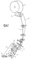
- 1 is the movable element quandrangular in shape which acts as an unwinding accelerator and in addition has a side slit for introducing the thread at each replacement of the feed cop 3. Its position is essentially concentric and perpendicular to the axis of bobbin 23 and, therefore, to cop 3 of wound thread.
- the said element 1 is placed with its bottom edge, at the start of rewinding thread 4 from cop 3 full of wound thread, at a distance from the tip of bobbin 23 essentially fluctuating at around 20mm (in accordance with the experimental results of the proposer);
- 2 is a shaft fixed to support plate 21, the latter being fixed as a single body to the spooler frame (not illustrated);
- 3 is the cop of wound thread made in a ring spinner;
- 4 is the path, shown by a dotted and dashed line, of the thread which is unwound from cop 3 below and runs upwards to wind itself in crisscross coils around the forming reel 14;
- 5 is a supporting frame which slides axially along shaft 2.
- the said frame 5 supports in a fixed way and as a single body quadrangular element 1, so that during its downward movement, shown by arrow 7, element 1 also moves perfectly synchronized and to an identical extent; 8 is a pneumatic actuator which through rod 11 moves frame 5, and thus element 1, upwards or downwards; 9 is a photocell, or any photoelectronic element, capable of detecting the presence in front of the cone 24 of wound thread, when the latter moves into the bottom part of cop 3. As the said cone 24 gradually descends, as rewinding of thread 4 from cop 3 proceeds, it will at a certain moment be in front of photocell 8 (see Fig.
- the support for the thread wound in the winding operation by a ring spinner to form a cop of yarn 3; 24 is the cone of wound thread and its truncated cone shape derives from the known method of winding the yarn onto bobbin 23 on the spindle of a ring spinner.
- a cop 3 full of wound thread is placed on the cop-holder pin (not shown) in the feed position. Its thread 4, using known means and devices, is brought to wind itself onto the forming reel 14 and thus rewinding of the thread begins, i.e. the transfer of thread 4 from cop 3 below to reel 14 above.
- the device covered by the present invention is stationary in the upper limit position (see Fig. 2).
- Photocell 9 does not detect in front the presence of the upper truncated cone shape of the wound thread 24 and quadrangular element 1 is positioned at a precise distance from the tip of bobbin 23.
- Thread 4 drawn upwards by supplier cylinder 12, on unwinding from cop 3, causes a gradual and continuous lowering of cone 24. This lowering will at a certain moment lead the truncated cone 24 to be positioned in front of photocell 9.
Landscapes
- Engineering & Computer Science (AREA)
- Quality & Reliability (AREA)
- Winding Filamentary Materials (AREA)
- Devices For Conveying Motion By Means Of Endless Flexible Members (AREA)
- Tension Adjustment In Filamentary Materials (AREA)
Applications Claiming Priority (2)
| Application Number | Priority Date | Filing Date | Title |
|---|---|---|---|
| IT02132390A IT1242991B (it) | 1990-08-29 | 1990-08-29 | Dispositivo attenuatore della tensione del filo in una unita' di roccatura |
| IT2132390 | 1990-08-29 |
Publications (1)
| Publication Number | Publication Date |
|---|---|
| EP0475475A1 true EP0475475A1 (de) | 1992-03-18 |
Family
ID=11180111
Family Applications (1)
| Application Number | Title | Priority Date | Filing Date |
|---|---|---|---|
| EP91202032A Withdrawn EP0475475A1 (de) | 1990-08-29 | 1991-08-07 | Vorrichtung zur Fadenspannungsverminderung in einer Spulvorrichtung |
Country Status (2)
| Country | Link |
|---|---|
| EP (1) | EP0475475A1 (de) |
| IT (1) | IT1242991B (de) |
Cited By (2)
| Publication number | Priority date | Publication date | Assignee | Title |
|---|---|---|---|---|
| US5377923A (en) * | 1991-07-01 | 1995-01-03 | Murata Kikai Kabushiki Kaisha | Yarn unwinding assisting device and yarn unwinding method in an automatic winder |
| US5445334A (en) * | 1992-01-30 | 1995-08-29 | Murata Kikai Kabushiki Kaisha | Cop changing mechanism for a winding unit |
Citations (4)
| Publication number | Priority date | Publication date | Assignee | Title |
|---|---|---|---|---|
| GB839368A (en) * | 1955-05-10 | 1960-06-29 | Reiners Walter | Method of unwinding thread and apparatus therefor |
| US3011736A (en) * | 1958-11-08 | 1961-12-05 | Reiners Walter | Yarn-ballooning control sleeve for winding machines |
| JPS61178373A (ja) * | 1985-01-31 | 1986-08-11 | Murata Mach Ltd | 糸解じよ補助装置 |
| EP0225670A1 (de) * | 1985-12-09 | 1987-06-16 | Picanol N.V. | Verfahren und Vorrichtung zum Abwickeln eines Fadens von einer Garnspule in Webmaschinen |
-
1990
- 1990-08-29 IT IT02132390A patent/IT1242991B/it active IP Right Grant
-
1991
- 1991-08-07 EP EP91202032A patent/EP0475475A1/de not_active Withdrawn
Patent Citations (4)
| Publication number | Priority date | Publication date | Assignee | Title |
|---|---|---|---|---|
| GB839368A (en) * | 1955-05-10 | 1960-06-29 | Reiners Walter | Method of unwinding thread and apparatus therefor |
| US3011736A (en) * | 1958-11-08 | 1961-12-05 | Reiners Walter | Yarn-ballooning control sleeve for winding machines |
| JPS61178373A (ja) * | 1985-01-31 | 1986-08-11 | Murata Mach Ltd | 糸解じよ補助装置 |
| EP0225670A1 (de) * | 1985-12-09 | 1987-06-16 | Picanol N.V. | Verfahren und Vorrichtung zum Abwickeln eines Fadens von einer Garnspule in Webmaschinen |
Non-Patent Citations (1)
| Title |
|---|
| PATENT ABSTRACTS OF JAPAN, Vol. 10, No. 388 (M-549)[2445] 25 December 1986; & JP-A-61 178 373 (MURATA MACH LTD) 11 August 1986, the whole document. * |
Cited By (2)
| Publication number | Priority date | Publication date | Assignee | Title |
|---|---|---|---|---|
| US5377923A (en) * | 1991-07-01 | 1995-01-03 | Murata Kikai Kabushiki Kaisha | Yarn unwinding assisting device and yarn unwinding method in an automatic winder |
| US5445334A (en) * | 1992-01-30 | 1995-08-29 | Murata Kikai Kabushiki Kaisha | Cop changing mechanism for a winding unit |
Also Published As
| Publication number | Publication date |
|---|---|
| IT1242991B (it) | 1994-05-23 |
| IT9021323A0 (it) | 1990-08-29 |
| IT9021323A1 (it) | 1992-02-29 |
Similar Documents
| Publication | Publication Date | Title |
|---|---|---|
| US5029762A (en) | Yarn winding apparatus and method | |
| EP2345612A2 (de) | Abziehvorrichtung | |
| CN114057020B (zh) | 用于控制气圈的装置和方法及包括该装置的卷绕单元 | |
| CN1321234C (zh) | 一种插入纬纱的方法和喂纱装置 | |
| CN101177220B (zh) | 用于操作生产交叉卷绕筒子的纺织机的卷绕头的方法 | |
| Gandhi | Yarn preparation for weaving: winding | |
| CN102249120B (zh) | 制造管纱的方法 | |
| EP3753886A1 (de) | Vorrichtung und verfahren zur steuerung eines ballons beim abwickeln eines fadens von einer spule | |
| US5161749A (en) | Device for correcting the variation in tension of the thread as it unwinds in a spooler | |
| RU2162816C2 (ru) | Нитеподающее устройство с улучшенным движением нити | |
| CS244425B2 (en) | Yarn guiding device | |
| CN105398880A (zh) | 储纱装置以及具备该储纱装置的纱线卷绕装置 | |
| EP0475475A1 (de) | Vorrichtung zur Fadenspannungsverminderung in einer Spulvorrichtung | |
| KR100338680B1 (ko) | 위사용 원사 이송량 측정 장치 | |
| EP0475483A1 (de) | Vorrichtung zur Fadenspannungsanpassung beim Abwickeln in einer Spulvorrichtung | |
| EP0475484A1 (de) | Vorrichtung zur gleichmässigen Fadenspannung beim Abwickeln in einer Spulvorrichtung | |
| EP0478023A1 (de) | Nachstellvorrichtung für die Spannung eines Fadens während seiner Abwickelung in einer Wickelmaschine | |
| JP2006124179A (ja) | 自動綾巻機の巻取り部における糸引き出しを最適化するための装置 | |
| JPH04214443A (ja) | 織機のよこ糸の計量装置 | |
| EP1127833A2 (de) | Automatische Wickeleinrichtung | |
| TW202009204A (zh) | 絲捲繞機 | |
| CA2148325A1 (en) | Method and device for winding continuous threads or yarns | |
| US2922272A (en) | Package size control and method | |
| US3449900A (en) | Twist retention yarn guide and method of uptwisting yarn | |
| CN211620721U (zh) | 一种输纱系统 |
Legal Events
| Date | Code | Title | Description |
|---|---|---|---|
| PUAI | Public reference made under article 153(3) epc to a published international application that has entered the european phase |
Free format text: ORIGINAL CODE: 0009012 |
|
| AK | Designated contracting states |
Kind code of ref document: A1 Designated state(s): CH DE FR GB LI |
|
| 17P | Request for examination filed |
Effective date: 19920622 |
|
| STAA | Information on the status of an ep patent application or granted ep patent |
Free format text: STATUS: THE APPLICATION IS DEEMED TO BE WITHDRAWN |
|
| 18D | Application deemed to be withdrawn |
Effective date: 19940301 |