EP0475475A1 - Device for reducing the tension of the thread in a spooler - Google Patents
Device for reducing the tension of the thread in a spooler Download PDFInfo
- Publication number
- EP0475475A1 EP0475475A1 EP91202032A EP91202032A EP0475475A1 EP 0475475 A1 EP0475475 A1 EP 0475475A1 EP 91202032 A EP91202032 A EP 91202032A EP 91202032 A EP91202032 A EP 91202032A EP 0475475 A1 EP0475475 A1 EP 0475475A1
- Authority
- EP
- European Patent Office
- Prior art keywords
- thread
- cop
- unwinding
- spooler
- axis
- Prior art date
- Legal status (The legal status is an assumption and is not a legal conclusion. Google has not performed a legal analysis and makes no representation as to the accuracy of the status listed.)
- Withdrawn
Links
Images

Classifications
-
- B—PERFORMING OPERATIONS; TRANSPORTING
- B65—CONVEYING; PACKING; STORING; HANDLING THIN OR FILAMENTARY MATERIAL
- B65H—HANDLING THIN OR FILAMENTARY MATERIAL, e.g. SHEETS, WEBS, CABLES
- B65H57/00—Guides for filamentary materials; Supports therefor
- B65H57/22—Guides for filamentary materials; Supports therefor adapted to prevent excessive ballooning of material
-
- B—PERFORMING OPERATIONS; TRANSPORTING
- B65—CONVEYING; PACKING; STORING; HANDLING THIN OR FILAMENTARY MATERIAL
- B65H—HANDLING THIN OR FILAMENTARY MATERIAL, e.g. SHEETS, WEBS, CABLES
- B65H59/00—Adjusting or controlling tension in filamentary material, e.g. for preventing snarling; Applications of tension indicators
- B65H59/02—Adjusting or controlling tension in filamentary material, e.g. for preventing snarling; Applications of tension indicators by regulating delivery of material from supply package
- B65H59/06—Adjusting or controlling tension in filamentary material, e.g. for preventing snarling; Applications of tension indicators by regulating delivery of material from supply package by devices acting on material leaving the package
-
- B—PERFORMING OPERATIONS; TRANSPORTING
- B65—CONVEYING; PACKING; STORING; HANDLING THIN OR FILAMENTARY MATERIAL
- B65H—HANDLING THIN OR FILAMENTARY MATERIAL, e.g. SHEETS, WEBS, CABLES
- B65H63/00—Warning or safety devices, e.g. automatic fault detectors, stop-motions ; Quality control of the package
- B65H63/08—Warning or safety devices, e.g. automatic fault detectors, stop-motions ; Quality control of the package responsive to delivery of a measured length of material, completion of winding of a package, or filling of a receptacle
- B65H63/082—Warning or safety devices, e.g. automatic fault detectors, stop-motions ; Quality control of the package responsive to delivery of a measured length of material, completion of winding of a package, or filling of a receptacle responsive to a predetermined size or diameter of the package
-
- B—PERFORMING OPERATIONS; TRANSPORTING
- B65—CONVEYING; PACKING; STORING; HANDLING THIN OR FILAMENTARY MATERIAL
- B65H—HANDLING THIN OR FILAMENTARY MATERIAL, e.g. SHEETS, WEBS, CABLES
- B65H2553/00—Sensing or detecting means
- B65H2553/40—Sensing or detecting means using optical, e.g. photographic, elements
- B65H2553/41—Photoelectric detectors
-
- B—PERFORMING OPERATIONS; TRANSPORTING
- B65—CONVEYING; PACKING; STORING; HANDLING THIN OR FILAMENTARY MATERIAL
- B65H—HANDLING THIN OR FILAMENTARY MATERIAL, e.g. SHEETS, WEBS, CABLES
- B65H2701/00—Handled material; Storage means
- B65H2701/30—Handled filamentary material
- B65H2701/31—Textiles threads or artificial strands of filaments
Definitions
- the present invention relates to a device for reducing the value of the unwinding tension of the thread in a spooler, which is designed to wind thread at high speed unwinding it from a cop below and collecting it on a forming reel above.
- Some textile working stages involve firstly transferring the thread, at the maximum speed possible, from one package to another.
- a thread produced in a spinning machine particularly in a continuous ring frame, is normally wound onto a spool or reel.
- the thread is then transported and supplied as a spinning cop for a rewinding stage.
- Spooling involves transferring (rewinding) from the starting cop to the collecting reel, with unravel unwinding, i.e. with axial extraction of the thread from the stationary cop.
- the starting package is often a cop coming from a ring spinner. Due to the mechanical limitations of a continuous ring frame, the spinning cops have a relatively small quantity of thread, up to a few hundred grams at most.
- the thread from several cops is collected in succession on a single reel.
- the purpose is always to obtain packages which are more suitable for the subsequent working stages such are dyeing, warping, inserting the weft, etc.
- the thread may be improved by removing sections with defects of various types.
- the continuous increase in the speed of such operations (expressed by the length of thread transferred in one unit of time) to reduce production costs, ever greater tension values in the thread are created and, therefore, more frequent breakages, which cause a considerable fall in the operating performance of the spooler and its productivity.
- breakage of the thread occurs under a tension which is greater than the thread's resistance to tensile stress.
- the thread on each spinning cop which has been supplied at a set position of a spooler, is drawn upwards with a tension value which gradually increases between the beginning and the end of the spinning cop during the unwinding phase, as is well known to the textile dressers.
- the thread is wound onto the reel at a low tension and thus the layer of thread wound at low tension may be expanded outwards of an end side of the reel due to the pressure of the overhanging layer of thread. Since usually to obtain one reel several spinning cops are used, the expanded part appears within each set period thus causing the formation of a reel with faulty winding which may give rise to unacceptable production for subsequent working stages.
- Means of controlling the spooling speed i.e. the winding speed, have also been proposed as a countermeasure to keep the thread tension at practically constant levels from the beginning to the end of the cop from which the thread is unwound, as described in US Patent 4805846.
- the device that reduces the value of the unwinding tension of the thread from the cop described in the present invention takes concrete form, in its practical application, by the fact that the supporting bracket of the movable element, which acts as an unwinding accelerator, can slide along an axis essentially parallel to the axis of the unwinding cop.
- 1 is the movable element quandrangular in shape which acts as an unwinding accelerator and in addition has a side slit for introducing the thread at each replacement of the feed cop 3. Its position is essentially concentric and perpendicular to the axis of bobbin 23 and, therefore, to cop 3 of wound thread.
- the said element 1 is placed with its bottom edge, at the start of rewinding thread 4 from cop 3 full of wound thread, at a distance from the tip of bobbin 23 essentially fluctuating at around 20mm (in accordance with the experimental results of the proposer);
- 2 is a shaft fixed to support plate 21, the latter being fixed as a single body to the spooler frame (not illustrated);
- 3 is the cop of wound thread made in a ring spinner;
- 4 is the path, shown by a dotted and dashed line, of the thread which is unwound from cop 3 below and runs upwards to wind itself in crisscross coils around the forming reel 14;
- 5 is a supporting frame which slides axially along shaft 2.
- the said frame 5 supports in a fixed way and as a single body quadrangular element 1, so that during its downward movement, shown by arrow 7, element 1 also moves perfectly synchronized and to an identical extent; 8 is a pneumatic actuator which through rod 11 moves frame 5, and thus element 1, upwards or downwards; 9 is a photocell, or any photoelectronic element, capable of detecting the presence in front of the cone 24 of wound thread, when the latter moves into the bottom part of cop 3. As the said cone 24 gradually descends, as rewinding of thread 4 from cop 3 proceeds, it will at a certain moment be in front of photocell 8 (see Fig.
- the support for the thread wound in the winding operation by a ring spinner to form a cop of yarn 3; 24 is the cone of wound thread and its truncated cone shape derives from the known method of winding the yarn onto bobbin 23 on the spindle of a ring spinner.
- a cop 3 full of wound thread is placed on the cop-holder pin (not shown) in the feed position. Its thread 4, using known means and devices, is brought to wind itself onto the forming reel 14 and thus rewinding of the thread begins, i.e. the transfer of thread 4 from cop 3 below to reel 14 above.
- the device covered by the present invention is stationary in the upper limit position (see Fig. 2).
- Photocell 9 does not detect in front the presence of the upper truncated cone shape of the wound thread 24 and quadrangular element 1 is positioned at a precise distance from the tip of bobbin 23.
- Thread 4 drawn upwards by supplier cylinder 12, on unwinding from cop 3, causes a gradual and continuous lowering of cone 24. This lowering will at a certain moment lead the truncated cone 24 to be positioned in front of photocell 9.
Abstract
The present invention relates to a device for reducing the value of the unwinding tension in a spooler which is designed to wind thread at high speed, the said device comprising a movable element (1), which acts as an unwinding accelerator and which at the tip surrounds the axis of the cop and along the said axis descends and moves concentrically to place itself in a lower position corresponding to a reduced minimum quantity of wound thread on the end part of the unwinding cop.
Description
- The present invention relates to a device for reducing the value of the unwinding tension of the thread in a spooler, which is designed to wind thread at high speed unwinding it from a cop below and collecting it on a forming reel above.
- Some textile working stages involve firstly transferring the thread, at the maximum speed possible, from one package to another. For example, a thread produced in a spinning machine, particularly in a continuous ring frame, is normally wound onto a spool or reel. The thread is then transported and supplied as a spinning cop for a rewinding stage. Spooling involves transferring (rewinding) from the starting cop to the collecting reel, with unravel unwinding, i.e. with axial extraction of the thread from the stationary cop. The starting package is often a cop coming from a ring spinner. Due to the mechanical limitations of a continuous ring frame, the spinning cops have a relatively small quantity of thread, up to a few hundred grams at most. Consequently, they are rewound and wound onto reels on which the quantity of thread and shape are suitable for use in a subsequent operation. Incidentally, the thread from several cops is collected in succession on a single reel. The purpose is always to obtain packages which are more suitable for the subsequent working stages such are dyeing, warping, inserting the weft, etc.
- During these transfer operations, the thread may be improved by removing sections with defects of various types. With the continuous increase in the speed of such operations (expressed by the length of thread transferred in one unit of time) to reduce production costs, ever greater tension values in the thread are created and, therefore, more frequent breakages, which cause a considerable fall in the operating performance of the spooler and its productivity. Incidentally, breakage of the thread occurs under a tension which is greater than the thread's resistance to tensile stress. The thread on each spinning cop, which has been supplied at a set position of a spooler, is drawn upwards with a tension value which gradually increases between the beginning and the end of the spinning cop during the unwinding phase, as is well known to the textile dressers. Indeed, when the layer of thread on each spinning cop decreases as the winding operation of the spooler progresses, the layer of thread thus diminished twists only round the bottom end of the cop and the thread, drawn out of it, travels upwards twisting back round the surface of the cop. In this case, the angle of separation of the layer of thread decreases and thereforefore tension is applied to the travelling thread due to the friction between the lengths of thread, or the contact of the thread with the cop and this may lead to breakage of the thread. This phenomenon occurs more readily in spoolers with a high winding speed. In the more modern spoolers thread transfer speeds of 20-30 m/s are reached.
- Furthermore, since the tension at the start of unwinding thread from a single spinning cop is low, the thread is wound onto the reel at a low tension and thus the layer of thread wound at low tension may be expanded outwards of an end side of the reel due to the pressure of the overhanging layer of thread. Since usually to obtain one reel several spinning cops are used, the expanded part appears within each set period thus causing the formation of a reel with faulty winding which may give rise to unacceptable production for subsequent working stages.
- In such an operating process a device is required which adjusts the winding tension of the thread between the start and finish of the cop thus reducing the unwinding tension at the end of the feed cop. Elements are known in the state of the art which by acting on the path of the thread in a fixed position guide it in precise unwinding forms which make it possible to limit the maximum tension values at which breakages of the winding thread frequently occur.
- These known elements, which act as unwinding accelerators (balloon-breakers) have various geometrical forms, as is well known by those working within the field. However, in the best of cases they only lessen the phenomenon, but do not lead to an optimum result of uniformity in the unwinding tension between the start and finish of unwinding the thread from the supply cop.
- Means of controlling the spooling speed, i.e. the winding speed, have also been proposed as a countermeasure to keep the thread tension at practically constant levels from the beginning to the end of the cop from which the thread is unwound, as described in US Patent 4805846.
- To obtain a thread tension which is approximately constant, in the said Patent the effect of the spooling speed on the thread tension is used. Indeed, by considerably reducing the spooling speed, in the interval of time in which the thread is unwound from the bottom part of the spinning cop, the tension is kept at a nearly uniform level for the entire duration of the spooling process. Such a solution will considerably reduce the operating performance of the spoolers in that for a certain interval of time the unwinding speed is considerably reduced and therefore a smaller quantity of thread will be transferred (wound on) in one unit of time. To all practical purposes this is unusable since it results in a considerable drop in the operating performance of the spooler and consequently in a reduction in its productivity.
- The aim of the present invention is to resolve the above-mentioned problems of the known state of the art by providing a device which ensures that the tension of the thread supplied in the spooler is kept at an essentially constant value during unwinding of the entire spinning cop and which offers the following advantages:
- it can be applied for any type of thread be it fine, medium or thick;
- it can be installed on existing spoolers;
- it enables the thread at high transfer speed to assume a geometrical configuration of contained energy dissipation which is highly important in the above-mentioned known state-of-the-art applications
- a movable element which acts as an unwinding accelerator and at the tip surrounds the axis of the cop and along the said axis descends and moves concentrically to place itself in a lower position corresponding to a reduced minimum quantity of wound thread on the end part of the unwinding cop. The said movable element is essentially quadrangular in shape and has also a side slit for the thread introduction which occurs each time that the feed cop is replaced;
- a kinematic mechanism which activates the said movement of the movable element parallel to the axis of the unwinding cop, the said kinematic mechanism being a pneumatic actuator, which is activated whenever there is a reduced minimum quantity of wound thread on the end part of the feed cop;
- an element capable of detecting the end position of unwinding of the thread from the cop, i.e. to detect the reduced minimum quantity of wound thread on the end part of the cop, in correspondence of which minimum quantity, said movement of the movable element is activated.This detection element is a photocell, or any known state-of-the-art optical sensor, positioned and secured in correspondence of the end part of accumulation of wound thread.
- The device that reduces the value of the unwinding tension of the thread from the cop described in the present invention, takes concrete form, in its practical application, by the fact that the supporting bracket of the movable element, which acts as an unwinding accelerator, can slide along an axis essentially parallel to the axis of the unwinding cop.
- The invention shall be described in detail below on the basis of the example of embodiment schematically represented in the drawings in the attached Figures, and additional details and characteristics shall be explained, in which connection it must be well understood that any variations in reciprocal positions of the elements and the consequent simplifications which could arise therefrom must be regarded as included in the protection requested as constructional variations covered by the general concept.
- In the attached drawings:
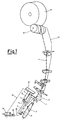
- Fig. 1 is an axonometric schematic view of the device covered by the present invention, showing also the path of the thread from the unwinding cop below up to the forming reel above and the said view shows the moment rewinding of the thread wound onto the cop supplying the spooler begins;
- Fig. 2 is an axonometric schematic view of the device covered by the present invention at the moment when the cop is full of wound thread and is therefore the moment when unwinding of the thread to transfer it to the reel above begins;
- Fig. 3 is an axonometric schematic view of the device covered by the present invention at the moment when the cop has on its end part a limited accumulation of wound thread and is therefore the moment just before unwinding of the thread from the cop to transfer it to the reel above ends.
- In the Figures the same elements bear the same reference numbers.
- Furthermore, for the purpose of clarity of the invention as a whole, in the Figures the parts not necessary to understanding the invention, such as the operating and functional units along the path of the thread, the motorisation centre of the thread guide roller, the reel-carrier arm, the various supporting structures and the means of supply, support and cop removal, are omitted.
- In the said attached Figures:
1 is the movable element quandrangular in shape which acts as an unwinding accelerator and in addition has a side slit for introducing the thread at each replacement of thefeed cop 3. Its position is essentially concentric and perpendicular to the axis ofbobbin 23 and, therefore, to cop 3 of wound thread. The said element 1 is placed with its bottom edge, at the start of rewindingthread 4 fromcop 3 full of wound thread, at a distance from the tip ofbobbin 23 essentially fluctuating at around 20mm (in accordance with the experimental results of the proposer); 2 is a shaft fixed to supportplate 21, the latter being fixed as a single body to the spooler frame (not illustrated); 3 is the cop of wound thread made in a ring spinner; 4 is the path, shown by a dotted and dashed line, of the thread which is unwound fromcop 3 below and runs upwards to wind itself in crisscross coils around the formingreel 14; 5 is a supporting frame which slides axially alongshaft 2. Thesaid frame 5 supports in a fixed way and as a single body quadrangular element 1, so that during its downward movement, shown by arrow 7, element 1 also moves perfectly synchronized and to an identical extent; 8 is a pneumatic actuator which throughrod 11 movesframe 5, and thus element 1, upwards or downwards; 9 is a photocell, or any photoelectronic element, capable of detecting the presence in front of thecone 24 of wound thread, when the latter moves into the bottom part ofcop 3. As the saidcone 24 gradually descends, as rewinding ofthread 4 fromcop 3 proceeds, it will at a certain moment be in front of photocell 8 (see Fig. 3), which on detecting its presence sends, throughwire 19, an electrical signal which activatessolenoid valve 18, the latter will operatedistributor 16 designed to control the direction of the flow of air under pressure so as to deliver throughpipe 20 the air under pressure toactuator 8 throughpipe 15. The saidactuator 8, viarod 11, will push supportingframe 5, as shown by arrow 7, so that quadrangular element 1 moves down to the position shown in Figure 3; 12 is the feed cylinder which rotatesreel 14 and, imparting an alternating back-and-forth movement, guides the thread onto thesaid reel 14; 10 is the schematic outline of the structure of a spooler; 14 is the reel which is a package of thread with a truncated cone shape, or a cylindrical shape, and the said package is produced by one spooler and intended for subsequent working stages (dyeing, warping, weaving, etc.); 22 is the supporting and anchoring plate of fixedphotocell 9; 23 is the thread winding bobbin, i.e. the support for the thread wound in the winding operation by a ring spinner to form a cop ofyarn 3; 24 is the cone of wound thread and its truncated cone shape derives from the known method of winding the yarn ontobobbin 23 on the spindle of a ring spinner. - The operation of the device for reducing the value of the unwinding tension in a spooler, illustrated by the attached drawings, can be easily understood by those working within the field.
- A
cop 3 full of wound thread is placed on the cop-holder pin (not shown) in the feed position. Itsthread 4, using known means and devices, is brought to wind itself onto the formingreel 14 and thus rewinding of the thread begins, i.e. the transfer ofthread 4 fromcop 3 below to reel 14 above. - The device covered by the present invention is stationary in the upper limit position (see Fig. 2). Photocell 9 does not detect in front the presence of the upper truncated cone shape of the
wound thread 24 and quadrangular element 1 is positioned at a precise distance from the tip ofbobbin 23.Thread 4, drawn upwards bysupplier cylinder 12, on unwinding fromcop 3, causes a gradual and continuous lowering ofcone 24. This lowering will at a certain moment lead thetruncated cone 24 to be positioned in front ofphotocell 9. - At the said moment photocell 9 will generate an electrical output signal which, through
wire 19, will activatesolenoid valve 18, which will operatedistributor 16 so that the flow of compressed air, frompipe 20, is emitted intopipe 15 to operateactuator 8. The saidactuator 8, viarod 11, will cause supportingframe 5 to descend to place quadrangular element 1 in the lower position, as illustrated in Figure 3. Movable quadrangular element 1 will be at a nearly constant distance from the rewinding point ofthread 4 fromcop 3 in the initial unwinding and final unwinding stage. Incidentally, the rewinding point ofthread 4 fromcop 3, i.e. the point at whichthread 4 on unwinding becomes detatched and separates fromcop 3, is localised exclusively in the restrictedtruncated cone band 24, as is well-known by those working within the field. The said essentially constant distance between quadrangular element 1 and the rewinding point below in the initial and final stages of unwinding ofthread 4 fromcop 3 results in an essentially uniform constant value of the tension ofthread 4 during unwinding ofcop 3, from which the thread is unwound to be transferred onto the formingreel 14 above. In this way the tension ofthread 4 is maintained at an essentially uniform level for the entire duration of the spooling process due to the operating presence of the device in question, which will consequently prevent most of the breakages ofthread 4 during its transfer fromcops 3 to reel 14. - All this enables extremely striking comparisons to be made particularly in the case of high-speed spoolers in which the speed of transfer of
thread 4 fromcop 3 to reel 14 is in the order of 2000 m/min and above. - Since the tension of the thread remains more or less uniform it is possible, as frequent accidental breakages do not occur, to obtain great improvements in the operating performance of spoolers and consequently in their productivity.
- It is purely by way of example that a pneumatic actuator has been used since similar kinematic movement mechanisms may be used capable of axially moving quadrangular-shaped element 1, which acts as an unwinding accelerator, and various modifications in detail may also be made to the form of supporting
frame 5 and its method of fixing to theactuator rod 11 without going beyond the scope of the invention.
the said device including:
Claims (5)
- A device for reducing the value of the unwinding tension in a spooler, which is designed to wind thread at high speed unwinding it from a cop below which supplies thread to a forming reel above and the said device is characterised in that it has:- a movable element which acts as an unwinding accelerator and at the tip surrounds the axis of the cop and along the said axis descends and moves concentrically to place itself in a lower position corresponding to a reduced minimum quantity of wound thread on the end part of the unwinding cop ;- a kinematic mechanism which activates the said movement of the movable element parallel to the axis of the unwinding cop;- an element capable of detecting the end position of unwinding of the thread from the cop, i.e. to detect the reduced minimum quantity of wound thread on the end part of the cop, in correspondence of which minimum quantity said movement of the movable element is activated.
- A device for reducing the value of the unwinding tension in a spooler, according to Claim 1, characterised in that the element that acts as an unwinding accelerator, since it contains and limits centrifugation of the thread, is essentially quadrangular in shape and has a side slit for the introduction of thread which occurs each time the supply cop is replaced.
- A device for reducing the value of the unwinding tension in a spooler, according to Claim 1, characterised in that the kinematic mechanism which moves the movable element along the axis of the cop is a pneumatic, or whatsoever type, actuator which is activated whenever there is a reduced minimum quantity of wound thread on the end part of the supply cop;
- A device for reducing the value of the unwinding tension in a spooler, according to Claim 1, characterised in that the element that detects the minimum end quantity of thread wound onto the supply cop is a photocell, or any other optical sensor, positioned and secured at the end part of the accumulation of wound thread.
- A device for reducing the value of the unwinding tension in a spooler, according to Claim 1, characterised in that the bracket supporting the movable element, which acts as an unwinding accelerator, can slide along an axis which is nearly parallel to the axis of the cop being unwound.
Applications Claiming Priority (2)
| Application Number | Priority Date | Filing Date | Title |
|---|---|---|---|
| IT2132390 | 1990-08-29 | ||
| IT02132390A IT1242991B (en) | 1990-08-29 | 1990-08-29 | THREAD TENSION ATTENUATING DEVICE IN A WRAPPING UNIT |
Publications (1)
| Publication Number | Publication Date |
|---|---|
| EP0475475A1 true EP0475475A1 (en) | 1992-03-18 |
Family
ID=11180111
Family Applications (1)
| Application Number | Title | Priority Date | Filing Date |
|---|---|---|---|
| EP91202032A Withdrawn EP0475475A1 (en) | 1990-08-29 | 1991-08-07 | Device for reducing the tension of the thread in a spooler |
Country Status (2)
| Country | Link |
|---|---|
| EP (1) | EP0475475A1 (en) |
| IT (1) | IT1242991B (en) |
Cited By (2)
| Publication number | Priority date | Publication date | Assignee | Title |
|---|---|---|---|---|
| US5377923A (en) * | 1991-07-01 | 1995-01-03 | Murata Kikai Kabushiki Kaisha | Yarn unwinding assisting device and yarn unwinding method in an automatic winder |
| US5445334A (en) * | 1992-01-30 | 1995-08-29 | Murata Kikai Kabushiki Kaisha | Cop changing mechanism for a winding unit |
Citations (4)
| Publication number | Priority date | Publication date | Assignee | Title |
|---|---|---|---|---|
| GB839368A (en) * | 1955-05-10 | 1960-06-29 | Reiners Walter | Method of unwinding thread and apparatus therefor |
| US3011736A (en) * | 1958-11-08 | 1961-12-05 | Reiners Walter | Yarn-ballooning control sleeve for winding machines |
| JPS61178373A (en) * | 1985-01-31 | 1986-08-11 | Murata Mach Ltd | Thread unwinding auxiliary device |
| EP0225670A1 (en) * | 1985-12-09 | 1987-06-16 | Picanol N.V. | Process for unwinding a thread from a reel in looms, and arrangement used therefor |
-
1990
- 1990-08-29 IT IT02132390A patent/IT1242991B/en active IP Right Grant
-
1991
- 1991-08-07 EP EP91202032A patent/EP0475475A1/en not_active Withdrawn
Patent Citations (4)
| Publication number | Priority date | Publication date | Assignee | Title |
|---|---|---|---|---|
| GB839368A (en) * | 1955-05-10 | 1960-06-29 | Reiners Walter | Method of unwinding thread and apparatus therefor |
| US3011736A (en) * | 1958-11-08 | 1961-12-05 | Reiners Walter | Yarn-ballooning control sleeve for winding machines |
| JPS61178373A (en) * | 1985-01-31 | 1986-08-11 | Murata Mach Ltd | Thread unwinding auxiliary device |
| EP0225670A1 (en) * | 1985-12-09 | 1987-06-16 | Picanol N.V. | Process for unwinding a thread from a reel in looms, and arrangement used therefor |
Non-Patent Citations (1)
| Title |
|---|
| PATENT ABSTRACTS OF JAPAN, Vol. 10, No. 388 (M-549)[2445] 25 December 1986; & JP-A-61 178 373 (MURATA MACH LTD) 11 August 1986, the whole document. * |
Cited By (2)
| Publication number | Priority date | Publication date | Assignee | Title |
|---|---|---|---|---|
| US5377923A (en) * | 1991-07-01 | 1995-01-03 | Murata Kikai Kabushiki Kaisha | Yarn unwinding assisting device and yarn unwinding method in an automatic winder |
| US5445334A (en) * | 1992-01-30 | 1995-08-29 | Murata Kikai Kabushiki Kaisha | Cop changing mechanism for a winding unit |
Also Published As
| Publication number | Publication date |
|---|---|
| IT9021323A0 (en) | 1990-08-29 |
| IT1242991B (en) | 1994-05-23 |
| IT9021323A1 (en) | 1992-02-29 |
Similar Documents
| Publication | Publication Date | Title |
|---|---|---|
| US5029762A (en) | Yarn winding apparatus and method | |
| EP2345612A2 (en) | Doffing apparatus | |
| CN216471447U (en) | Device for controlling balloon and winding unit comprising same | |
| CN212981979U (en) | Device for controlling an air bag during the unwinding of a yarn from a spool | |
| CN102249120B (en) | Method for manufacturing spinning cops | |
| KR100516487B1 (en) | Method for inserting weft threads and thread feed device | |
| Gandhi | Yarn preparation for weaving: winding | |
| CN101177220A (en) | Method for operating winding head of textile machine for preparing cross-wound bobbin | |
| CN101346297B (en) | Method for spooling a thread on a textile machine which produces crosswound bobbins, and textile machine which produces crosswound bobbins | |
| CN105398880A (en) | Yarn Storage Device And Yarn Winding Device Equipped With Yarn Storage Device | |
| US5161749A (en) | Device for correcting the variation in tension of the thread as it unwinds in a spooler | |
| RU2162816C2 (en) | Thread feeder with improved motion of thread | |
| US3920193A (en) | Winding apparatus with automatic changing of tubes or the like | |
| EP0475475A1 (en) | Device for reducing the tension of the thread in a spooler | |
| KR100338680B1 (en) | Measuring delivery device | |
| CN1643194B (en) | Centrifugal spinning device | |
| EP0475483A1 (en) | Device for adapting the tension of the thread as it unwinds in a spooler | |
| EP0475484A1 (en) | Device for making the tension of the thread uniform as it unwinds in a spooler | |
| CS244425B2 (en) | Yarn guiding device | |
| EP0478023A1 (en) | Device for adjusting the tension of the thread as it unwinds in a spooler | |
| JPH04214443A (en) | Weft-metering device of loom | |
| EP1127833A2 (en) | Automatic winder | |
| CN112424100B (en) | Yarn winding machine | |
| US4552320A (en) | Method and apparatus for forming snarl-free thread reserves | |
| EP0275596B1 (en) | Device for preventing the formation of yarn loops, and for saving the intaken yarn on the winding units |
Legal Events
| Date | Code | Title | Description |
|---|---|---|---|
| PUAI | Public reference made under article 153(3) epc to a published international application that has entered the european phase |
Free format text: ORIGINAL CODE: 0009012 |
|
| AK | Designated contracting states |
Kind code of ref document: A1 Designated state(s): CH DE FR GB LI |
|
| 17P | Request for examination filed |
Effective date: 19920622 |
|
| STAA | Information on the status of an ep patent application or granted ep patent |
Free format text: STATUS: THE APPLICATION IS DEEMED TO BE WITHDRAWN |
|
| 18D | Application deemed to be withdrawn |
Effective date: 19940301 |