EP0474521B1 - Gerät zur zerstörungsfreien Untersuchung einer Mehrzahl von Teilstücken von Verbindungen - Google Patents
Gerät zur zerstörungsfreien Untersuchung einer Mehrzahl von Teilstücken von Verbindungen Download PDFInfo
- Publication number
- EP0474521B1 EP0474521B1 EP91402003A EP91402003A EP0474521B1 EP 0474521 B1 EP0474521 B1 EP 0474521B1 EP 91402003 A EP91402003 A EP 91402003A EP 91402003 A EP91402003 A EP 91402003A EP 0474521 B1 EP0474521 B1 EP 0474521B1
- Authority
- EP
- European Patent Office
- Prior art keywords
- probe
- memory
- portions
- microprocessor
- adjustment
- Prior art date
- Legal status (The legal status is an assumption and is not a legal conclusion. Google has not performed a legal analysis and makes no representation as to the accuracy of the status listed.)
- Expired - Lifetime
Links
- 239000000523 sample Substances 0.000 claims description 85
- 238000001514 detection method Methods 0.000 claims description 9
- 238000010276 construction Methods 0.000 claims description 8
- 230000001066 destructive effect Effects 0.000 claims description 5
- 230000002093 peripheral effect Effects 0.000 claims description 5
- 230000005055 memory storage Effects 0.000 claims 1
- 238000004804 winding Methods 0.000 description 29
- 238000002347 injection Methods 0.000 description 11
- 239000007924 injection Substances 0.000 description 11
- 238000005259 measurement Methods 0.000 description 8
- 230000003014 reinforcing effect Effects 0.000 description 6
- RTAQQCXQSZGOHL-UHFFFAOYSA-N Titanium Chemical compound [Ti] RTAQQCXQSZGOHL-UHFFFAOYSA-N 0.000 description 4
- 229910052719 titanium Inorganic materials 0.000 description 4
- 239000010936 titanium Substances 0.000 description 4
- XAGFODPZIPBFFR-UHFFFAOYSA-N aluminium Chemical compound [Al] XAGFODPZIPBFFR-UHFFFAOYSA-N 0.000 description 3
- 229910052782 aluminium Inorganic materials 0.000 description 3
- 230000000712 assembly Effects 0.000 description 3
- 238000000429 assembly Methods 0.000 description 3
- 238000010586 diagram Methods 0.000 description 3
- 230000002787 reinforcement Effects 0.000 description 3
- 230000003321 amplification Effects 0.000 description 2
- 230000007797 corrosion Effects 0.000 description 2
- 238000005260 corrosion Methods 0.000 description 2
- 238000003199 nucleic acid amplification method Methods 0.000 description 2
- 238000000926 separation method Methods 0.000 description 2
- 230000001360 synchronised effect Effects 0.000 description 2
- 238000012795 verification Methods 0.000 description 2
- 238000012800 visualization Methods 0.000 description 2
- 240000008042 Zea mays Species 0.000 description 1
- 238000012550 audit Methods 0.000 description 1
- 230000015572 biosynthetic process Effects 0.000 description 1
- 230000006835 compression Effects 0.000 description 1
- 238000007906 compression Methods 0.000 description 1
- 239000000470 constituent Substances 0.000 description 1
- 230000006837 decompression Effects 0.000 description 1
- 239000012777 electrically insulating material Substances 0.000 description 1
- 230000005284 excitation Effects 0.000 description 1
- 238000001914 filtration Methods 0.000 description 1
- 230000006870 function Effects 0.000 description 1
- 239000000463 material Substances 0.000 description 1
- -1 methacrylic compound Chemical class 0.000 description 1
- 230000003071 parasitic effect Effects 0.000 description 1
- 230000010363 phase shift Effects 0.000 description 1
- 230000000284 resting effect Effects 0.000 description 1
- 230000009897 systematic effect Effects 0.000 description 1
- 229910000859 α-Fe Inorganic materials 0.000 description 1
Images


Classifications
-
- G—PHYSICS
- G01—MEASURING; TESTING
- G01N—INVESTIGATING OR ANALYSING MATERIALS BY DETERMINING THEIR CHEMICAL OR PHYSICAL PROPERTIES
- G01N27/00—Investigating or analysing materials by the use of electric, electrochemical, or magnetic means
- G01N27/72—Investigating or analysing materials by the use of electric, electrochemical, or magnetic means by investigating magnetic variables
- G01N27/82—Investigating or analysing materials by the use of electric, electrochemical, or magnetic means by investigating magnetic variables for investigating the presence of flaws
- G01N27/90—Investigating or analysing materials by the use of electric, electrochemical, or magnetic means by investigating magnetic variables for investigating the presence of flaws using eddy currents
- G01N27/9073—Recording measured data
- G01N27/9086—Calibrating of recording device
-
- G—PHYSICS
- G01—MEASURING; TESTING
- G01N—INVESTIGATING OR ANALYSING MATERIALS BY DETERMINING THEIR CHEMICAL OR PHYSICAL PROPERTIES
- G01N27/00—Investigating or analysing materials by the use of electric, electrochemical, or magnetic means
- G01N27/72—Investigating or analysing materials by the use of electric, electrochemical, or magnetic means by investigating magnetic variables
- G01N27/82—Investigating or analysing materials by the use of electric, electrochemical, or magnetic means by investigating magnetic variables for investigating the presence of flaws
- G01N27/90—Investigating or analysing materials by the use of electric, electrochemical, or magnetic means by investigating magnetic variables for investigating the presence of flaws using eddy currents
- G01N27/9013—Arrangements for scanning
- G01N27/902—Arrangements for scanning by moving the sensors
Definitions
- the present invention relates to a device, in particular portable, for the non-destructive examination of a surface along a line.
- this device can be used in many applications such as the non-destructive examination of welds of tubes, pipes, etc., the present invention will be more particularly described below in connection with the non-destructive examination of junctions panels constituting the skin of the fuselage of an aircraft.
- the skin of the fuselage of an aircraft consists of individual riveted panels and that the edges of two adjacent panels overlap in a sealed manner and are assembled by means of rivets or the like.
- Such rivet junctions tire a lot during the use of the aircraft, in particular because of the compression and decompression cycles to which the fuselage of the latter is subjected. This can result in the formation of cracks developing from the rivet holes in the panels and the separation of the edges of the junction. As a result, the junctions weaken and can be attacked by corrosion. It is therefore essential to periodically monitor said junctions in order to know their state with regard to the development of cracks, the separation of edges and the progression of corrosion.
- said control means are adjusted so that the examination of the probe is optimal.
- the sections of junctions examined may have different constitutions and it is necessary, for the results of the examination to be satisfactory, to adapt the adjustment of the probe to each section of junction examined. according to its constitution.
- the object of the present invention is to remedy this drawback.
- the probe can be adjusted automatically, optimally, without operator intervention.
- Said first and second memory means can be independent. However, they can also be merged into a single memory thus containing, for each junction section, the operating setting to be applied to said probe.
- the content of said second memory means results from a plurality of prior examinations made with different settings of said probe on known samples of constitutions similar to those of said sections of junctions.
- the device allowing the use of said device to be extended to junctions of very different constitutions, several interchangeable probes and display means associated with said microprocessor means are provided, and said second means with memory additionally contain, for each specific constitution of junction segment, the information indicating which of said probes is most suitable for examining this specific constitution and said microprocessor means display this information on said display means.
- the operator can choose the most suitable probe for examining the junction section in progress, the adjustment of this probe being then automatically ensured by said control means, as described above.
- the device according to the invention comprises, on the one hand a control unit close to said probe, incorporating said control means, as well as the means for reading said probe and said microprocessor means and, on the other hand , a plurality of peripheral devices, comprising said first and second memory means and at least one storage unit and intended to be placed at a fixed position some distance from the examined junction sections.
- said probe can be of the eddy current type.
- said adjustment means comprise, to supply the probe (s), an adjustable carrier frequency generator.
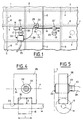
- Figure 1 schematically illustrates part of the device according to the invention, examining a section of riveted junction.
- Figure 2 is a front view, on a larger scale, illustrating connections between the individual panels of the skin of an aircraft fuselage.
- Figures 3a to 3e are sections along line III-III of Figure 2, illustrating several possible constitutions for the junctions between said panels.
- Figure 4 is an enlarged front view showing the probe holder and its mounting on the guide rod of the device.
- FIG. 5 is a side view corresponding to FIG. 4.
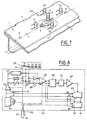
- Figure 6 is the block diagram of the device according to the present invention.
- FIG. 7 illustrates, diagrammatically in perspective, the structure of an embodiment of a probe for the device of the invention.
- FIG. 8 shows the block diagram of the means for adjusting and reading the probe of FIG. 7.
- the portion 1 of the fuselage skin for aircraft shown diagrammatically in FIG. 1, consists, as usual, of individual rectangular panels 2 of aluminum assembled together and defining transverse junction lines 3 and junction lines longitudinal 4.
- transverse junction lines 3 correspond to the location of the fuselage frames (not shown) and transverse lines 5 of rivets 6 (for example made of titanium) are provided for joining the transverse edges of the panels 2 to said frames.
- the longitudinal junction lines 4 are of the overlapping type and the edges 2e and 2i of two adjacent panels 2 overlap and are assembled by means of two parallel lines 7 and 8 of rivets 9 (titanium).
- these edges overlapping 2e and 2i press between them a reinforcing strip 10 and a seal 11 is disposed between the end (forming the visible junction line 4) of the outer edge 2e and the outer wall of the inner edge 2i.
- Reinforcement strips and sections 12 and 13 are provided on the inside of the skin 1 of the fuselage and are joined to the latter by the lines 7 and 8 of the rivets 9.
- Figures 3b to 3e show, in section, alternative construction of the junction between two adjacent panels.
- the reinforcing strip 10 has been deleted, while in Figure 3c, it is the reinforcing profile 12 which has been eliminated.
- the embodiment of FIG. 3d has neither reinforcing strip 10 nor reinforcing profile 12.
- the construction between the junction is similar to that of FIG. 3d, but the reinforcing profile 13 is associated with a additional reinforcement angle 13a, one wing of which is fixed to the panels by means of the rivets 9 of the line 7 and the other to the reinforcement 13, by means of rivets 13b.
- FIG 1 there is shown schematically and partially the device according to the present invention, during verification of the longitudinal line 7 of rivets 9 of a skin panel 2.
- This device comprises a guide rod 14, the length corresponds to that of at least one panel or to that of a few panels 2, for example to the length of two or three panels 2, and over which a slider 15 can slide. It further comprises, at one of its ends, a measurement box 16, capable of indicating, at any time, the position of the cursor 15 along the rod 14.
- the assembly 14-15-16 is of the type described in patent US-A-3 898 555.
- suction cups 17 and 18 are associated two suction cups 17 and 18, of known type, actuable by a manual lever 20.
- the suction cup 17 is rigidly linked to the measurement box 16, while the suction cup 18 is integral with a slide 19, which can slide along the guide rod 14.
- the device according to the invention further comprises a control box 21, integral with the suction cup 17 and receiving the measurements from the box 16, by the link 22 and the indications of a probe 23, by the link 24.
- the box 21 is connected by a link 25 to a plurality of peripheral devices, as shown in FIG. 6, in which a more complete variant 21 'of the housing 21 is shown separated from the suction cup 17.
- Fingers 26 and 27, respectively integral with the housing 16 and the slide 19, can cooperate with the end of the outer edge 2e and / or with the seal 11 to arrange the guide rod 14 parallel to the junction line 4, and therefore at line 7 of rivets 9, to be examined.
- the probe 23 is carried by a probe holder 28.
- the latter advantageously consists of a thick transparent plate, for example of a methacrylic compound, in which said probe is incorporated.
- the probe holder 28 has a notch 30, the length L of which is such that it can fit together with gentle friction on the cursor 15 and whose depth l is such that, when it is fitted on the cursor 15, the edge 29 is in abutment on the guide rod 14, the probe 23 then being centered on the line 7 of the rivets 9.
- the probe holder 28 further comprises a reticle 31 centered on the rivet 9i of line 7 when the probe 23 is centered on the rivet 9j of line 7.
- the probe 23 In the direction of the skin 1 of the fuselage, the probe 23 is provided with a support and sliding pad 32, while on the opposite side, it comprises a socket 33 for connection to the link 24.
- the probe 23 - probe holder 28 assembly can be easily mounted or dismounted.
- the device according to the invention is associated with a plurality of probe 23 - probe holder 28 assemblies, geometrically identical, but in which the probes 23 have different electrical performances. Thus, depending on the characteristics required of the probe by the examination to be carried out, one or the other of said interchangeable assemblies 23-28 is chosen.
- control box 21 ′ comprises the control and reading means 34, for the probe 23, connected to the latter by the link 24. These control and reading means are provided with a control input 35.
- control unit 21 ′ comprises a microprocessor 36, in connection with the outputs of said control and reading means 34, via an analog-digital converter 37. The latter can convert also the information from the measurement box 16, to address them in the form suitable for the microprocessor 36.
- the microprocessor 36 is also linked to a keyboard 38, a printer 39, a display device 40, a storage unit 41, for example of the hard disk type, a programming floppy disk 42 and another display device 46 nearby. of the operator ensuring the movement of the probe.
- the device comprises, in accordance with the present invention, a memory 43 containing the settings that the control and reading means 34 must apply to the probe 23, according to the particular constitution (see FIGS. 3a to 3e) of the junction to be examined.
- the information stored in memory 43 is obtained by learning, that is to say by examining, in a preparatory phase, known samples of each of the different junction constitutions with different settings of several of said probes 23, then by storing in said memory 43 the identification of the probe 23 and the adjustment parameters of the latter which are best suited to each type of constitution.
- the output 44 of the memory 43 is connected to the input 35 of said control and reading means 34 by a link 45.
- the memory 43 is in connection with the microprocessor 36.
- the assembly of the elements 14 to 28 is portable and can be available to a first operator moving, in one way or another, relative to the skin 1 of the fuselage, in the vicinity of this one.
- the display device 43 which can also be portable and of small size, is also available to this first operator.
- all the other peripheral devices 38 to 43 can be placed far from the place where the verification of the riveted connections is carried out and they are for example placed on the ground, available to a second operator.
- the different connections between the control box 21 ′ and the peripheral devices 38 to 43 are brought together in the link 25 shown in FIG. 1.
- the first operator which is located near a junction portion 4 to be checked, placed between the frames C n and C n + 1 and which carries all of the elements 14 to 28 and the display device 46, fixes the suction cups 17 and 18 on the skin 1 so that they are located on either side of said frames and that the fingers 26 and 27 bear against the seal 11. It is then certain that the rod 14 is parallel to this junction portion 4 and that the probe 23 is located opposite the line 7.
- the second operator enters, by the keyboard 38, various information, such as the aircraft number, the number of the fuselage section , the numbers of the frames limiting the junction portion 4, the number of the junction 4, the side (left or right) of the fuselage, etc. capable of allowing the identification of each junction section.
- the microprocessor 36 therefore knows, through memory 43, the exact particular constitution of a junction section 4 to be examined. It can therefore display on the display devices 40 and 46 the probe 23 which is best suited for the examination. The operator can therefore choose the assembly 23-28 from the plurality of interchangeable assemblies 23-28 and place it on the cursor 15 by connecting it to the link 24 by means of the connector 23. Then, the microprocessor 36 can control accordingly the memory 43 so that it addresses to the probe 23 chosen, by means of the means 34, the specific settings for the junction section 4 that said probe will examine.
- the first operator begins by moving the cursor 15 - probe holder 28 assembly towards one of the ends of the junction section 4 to be checked and, using the reticle 31, he aims at the center of an end rivet 9 so that the probe 23 is superimposed on the first of the rivets 9 of the line 7 of said section. Then it performs the same operation at the other end of it. Consequently, the microprocessor 36 receives from the measurement box 16, the respective abscissae of these two views and, by subtraction, it deduces therefrom the distance separating the frames C n and C n + 1 and serving as a measurement window for said probe 23 .
- the first operator manually slides the probe holder 28 and the cursor 15 along the guide rod 14, from one of said frames C n or C n + 1 to the other, while maintaining the sliding pads. 32 pressing against the skin 1.
- the probe 23 therefore successively explores the riveting line 7.
- each time that the probe 23 passes in front of a rivet it emits a pulse.
- the number of pulses obtained optionally makes it possible to count the rivets of the line section 7 examined.
- the microprocessor 36 is capable of detect any identification error of the section 4 examined.
- the first operator does not have to deal with the centering of the probe 23 relative to the rivets 9. He can therefore control the images appearing on the screen of the device 46. He therefore sees there appear the image of the different rivets of the section and the image of any cracks. Likewise, the second operator sees the same images appear on the screen of the device 40. In the event of anomalies or ambiguities, the first operator can bring back the cursor 15 and the probe holder 28 while maintaining the pads 32 resting on the skin 1 to examine the corresponding area at leisure.
- the information giving rise to the images on the screens of the devices 40 and 46 are stored in the storage unit 41 and printed on a medium by the printer 39.
- the first operator inhibits the action of the suction cup 17 (by action on the lever 20) and he can therefore slide the assembly 14 to 17 towards the suction cup 18, remaining secured to the skin, since then the rod 14 can slide along its axis in the fixed slide 19. It can bring the released suction cup 17 in the 171 position (see Figure 1), then fix it on the skin 1 at this position by actuation of the lever 20. Then, it actuates the lever 20 of the suction cup 18 in the direction of disengagement and it can slide the assembly 18-19, in the same direction as previously for the suction cup 17, to bring the suction cup 18 to position 181.
- the device according to the invention is then ready for the examination of the panel 2 adjacent to that which has just been examined.
- the first operator can monitor the examination on his control screen 46 and, thanks to the possibility of movement of the probe holder 28, in both directions, this operator can go back in order to examine a suspect area or dispel an ambiguity.
- the microprocessor 36 stores information in its memory 41 only for a direction of movement of the cursor 15 on the rod 14 and erases from this memory the information already contained, when the cursor 15 moves in the opposite direction, in correspondence with the amplitude of said reverse movement.
- the probes 23 can be of the eddy current type.
- the eddy current probe 23 the diagram of which is shown schematically in perspective in the figure 7 above the panels to be examined, comprises a primary injection winding P and four secondary detection windings S1 to S4, each of the primary and secondary windings comprising a ferrite core or the like and these five windings and their cores being embedded in a body of magnetically and electrically insulating material (not shown).
- the relative positions of the five windings are fixed, the injection winding P being arranged centrally, while the detection windings S1 to S4 are diametrically opposite in pairs, the windings S1 and S3 determining a first axis orthogonal to a second axis determined by the windings S2 and S4.
- the axis of the injection winding P passes through the point of intersection of these first and second axes and the windings S1 to S4 are equidistant from this point of intersection.
- the injection winding P is provided with two terminals 50 and 51 between which an electric excitation signal is injected, while the windings S1 to S4 are connected in series so that the windings of detection S1 and S3 are in the same direction and that the windings S2 and S4 are in the opposite direction to the windings S1 and S3.
- the series connection of the detection windings S1 to S4 has two terminals 51 and 52 between which the detection signal is collected, that is to say a signal of imbalance of the probe.
- the windings S1 to S4 are identical and balanced so that, when the injection winding P receives the injection signal between its terminals 50 and 51, it generates in a homogeneous surface 2 induced currents along lines of circular currents and giving rise in the detection windings S1 to S4 to equal and two to two opposite signals, so that the signal at terminals 51 and 52 is zero.
- the windings S1 and S3 are considered to be measurement windings, while the windings S2 and S4 are considered to be compensation windings.
- a probe 23 balanced to give a zero signal between its output terminals 51 and 52 when the surface 2 is homogeneous or when it is opposite a homogeneous part of a heterogeneous surface will provide an imbalance signal when the lines of induced currents will undergo deformations due to heterogeneities, due for example to the rivets 9 or to cracks starting from the holes in the panels 2 through which the said rivets pass.
- the probe 23 is connected to the adjustment and reading device 34, via a link 24.
- the device 34 comprises an electric generator 53 of a carrier frequency signal, preferably sinusoidal , and of a signal of the same frequency, but phase shifted back 90 °. This gives a 90 ° phase reference signal intended to serve as an injection signal and a 0 ° phase reference signal.
- the injection signal (phase 90 °) is applied, on the one hand, to an amplifier 54 current adapter and, on the other hand, to a double demodulator synchronous 55 and a phase shifter 56.
- the 0 ° phase reference signal is applied to the double synchronous demodulator 55 and to the phase shifter 56.
- the injection signal is transmitted to the primary winding P via an adapter 57.
- the secondary windings S1 to S4 are connected to an impedance adapter system 58 followed by a detection amplifier 59, a device 60 for balancing the probe 23, a possible filter 61 intended to eliminate the parasitic frequencies of the carrier frequency and of an amplifier 62.
- the injection signal applied by the generator 53 to the primary winding P via the amplifier 54 and the adapter 57 is detected by the windings S1 to S4, then adapted in impedance in the adapter 58, after which, after amplification (in 59), balancing (in 60), filtering (in 61) and amplification (in 62), it is applied to the double demodulator 55.
- the generator 53 be of adjustable frequency and that the memory 43 address said audit. generator, by the link 45, specific adjustment orders as a function of the constitution of the junction sections. In addition, through the link 45, the memory 43 can appropriately adjust the gains of the amplifiers 54 and 59, and the phase shifter 56. In FIG. 8, the different commands transmitted are represented by dashed lines.
Landscapes
- Chemical & Material Sciences (AREA)
- Analytical Chemistry (AREA)
- General Health & Medical Sciences (AREA)
- Physics & Mathematics (AREA)
- Health & Medical Sciences (AREA)
- Life Sciences & Earth Sciences (AREA)
- Chemical Kinetics & Catalysis (AREA)
- Biochemistry (AREA)
- Electrochemistry (AREA)
- General Physics & Mathematics (AREA)
- Immunology (AREA)
- Pathology (AREA)
- Investigating Or Analyzing Materials By The Use Of Magnetic Means (AREA)
- Investigating Or Analyzing Materials By The Use Of Ultrasonic Waves (AREA)
- Measuring Leads Or Probes (AREA)
Claims (5)
- Vorrichtung zur zerstörungsfreien Prüfung einer Vielzahl von genieteten oder ähnlichen Verbindungsabschnitten (7), wobei jeder der Abschnitte (7) durch Identifizierungsmittel einzeln identifizierbar ist und die Vorrichtung umfaßt:- mindestens eine elektrische Erfassungssonde (23), die längs der Verbindungsabschnitte (7) verschoben werden kann;- Mittel (34) zur Steuerung des Betriebs der Sonde (23);- Mittel (41) zur Registrierung der Ergebnisse der Prüfungen der Abschnitte durch die Sonde;- Mikroprozessormittel (36) zur Steuerung der Prüfungen der Abschnitte (7) durch die Sonde (23) und- Anzeigemittel (40,46), die den Mikroprozessormitteln (36) zugeordnet sind,
dadurch gekennzeichnet, daß sie umfaßt:- eine Vielzahl von unterschiedlichen, jedoch austauschbaren Sonden (23);- erste Speichermittel (43), die für jeden Verbindungsabschnitt (7) dessen spezifischen Aufbau enthalten, und- zweite Speichermittel (43), die für jeden spezifischen Aufbau eines Verbindungsabschnitts (7) die Information enthalten, die angibt, welche der Sonden (23) für die Prüfung dieses spezifischen Aufbaus am besten geeignet ist, sowie die Information, die die für die Sonde (23) anzuwendende Betriebseinstellung angibt,- die Mikroprozessormittel (36), die den Inhalt der ersten und zweiten Speichermittel (43) nutzen, um an den Anzeigemitteln (40,46) die am besten geeignete Sonde anzuzeigen und um die Einstellmittel (34) zu kontrollieren, die an die am besten geeignete Sonde (23) die dem spezifischen Aufbau des zu prüfenden Verbindungsabschnitts entsprechende Einstellung geben. - Vorrichtung nach Anspruch 1,
dadurch gekennzeichnet, daß die ersten und zweiten Speichermittel (43) zu einem einzigen Speicher (43) verschmolzen werden, der für jeden Verbindungsabschnitt (7) die an die Sonde (23) anzulegende Betriebseinstellung enthält. - Vorrichtung nach einem der Ansprüche 1 oder 2,
dadurch gekennzeichnet, daß der Inhalt der zweiten Speichermittel (43) das Ergebnis einer Vielzahl von Vorprüfungen ist, die mit unterschiedlichen Einstellungen der Sonde an bekannten Proben durchgeführt wurden, deren Aufbau dem der Verbindungsabschnitte ähnlich ist. - Vorrichtung nach einem der Ansprüche 1 bis 3,
dadurch gekennzeichnet, daß sie einerseits ein Steuergehäuse (21') in der Nähe der Sonde (23), in dem sich die Einstellmittel (34) sowie die Ablesemittel der Sonde und die Mikroprczessormittel (36) befinden, und andererseits eine Vielzahl von Peripheriegeräten hat, zu denen die ersten und zweiten Speichermittel und mindestens eine Speichereinheit gehören, die als stationäre Anlage abgesetzt von den geprüften Verbindungsabschnitten angeordnet sind. - Vorrichtung nach einem der Ansprüche 1 bis 4,
dadurch gekennzeichnet, daß die Sonde (23) eine Wirbelstromsonde ist, und dadurch, daß die Steuermittel (34) mindestens die an die Sonde entsprechend dem spezifischen Aufbau eines Prüfabschnitts angelegte Trägerfrequenz steuern.
Applications Claiming Priority (2)
| Application Number | Priority Date | Filing Date | Title |
|---|---|---|---|
| FR9011074 | 1990-09-06 | ||
| FR9011074A FR2666655B1 (fr) | 1990-09-06 | 1990-09-06 | Dispositif pour l'examen non destructif d'une pluralite de troncons de jonctions. |
Publications (2)
| Publication Number | Publication Date |
|---|---|
| EP0474521A1 EP0474521A1 (de) | 1992-03-11 |
| EP0474521B1 true EP0474521B1 (de) | 1996-05-29 |
Family
ID=9400130
Family Applications (1)
| Application Number | Title | Priority Date | Filing Date |
|---|---|---|---|
| EP91402003A Expired - Lifetime EP0474521B1 (de) | 1990-09-06 | 1991-07-17 | Gerät zur zerstörungsfreien Untersuchung einer Mehrzahl von Teilstücken von Verbindungen |
Country Status (5)
| Country | Link |
|---|---|
| US (1) | US5406500A (de) |
| EP (1) | EP0474521B1 (de) |
| CA (1) | CA2050442C (de) |
| DE (1) | DE69119849T2 (de) |
| FR (1) | FR2666655B1 (de) |
Families Citing this family (7)
| Publication number | Priority date | Publication date | Assignee | Title |
|---|---|---|---|---|
| FR2696549B1 (fr) * | 1992-10-06 | 1994-12-16 | Aerospatiale | Procédé et dispositif pour l'examen non destructif de jonctions au moyen d'une sonde à courants de Foucault. |
| US6037768A (en) * | 1997-04-02 | 2000-03-14 | Iowa State University Research Foundation, Inc. | Pulsed eddy current inspections and the calibration and display of inspection results |
| US6823736B1 (en) | 2002-11-20 | 2004-11-30 | The United States Of America As Represented By The Secretary Of The Navy | Nondestructive acoustic emission testing system using electromagnetic excitation and method for using same |
| GB2414809A (en) * | 2003-01-23 | 2005-12-07 | Jentek Sensors Inc | Damage tolerance using adaptive model-based methods |
| GB2417091A (en) * | 2004-08-03 | 2006-02-15 | Advanced Analysis And Integrat | Aircraft test and measuring instruments |
| US7802352B2 (en) * | 2005-04-13 | 2010-09-28 | Newfrey Llc | Monitoring system for fastener setting tool |
| CN110842491B (zh) * | 2019-12-06 | 2021-03-02 | 宁德侨云电子有限公司 | 一种线束隔离板的自动化生产方法 |
Family Cites Families (6)
| Publication number | Priority date | Publication date | Assignee | Title |
|---|---|---|---|---|
| FR2541773B1 (fr) * | 1983-02-24 | 1985-06-14 | Aerospatiale | Dispositif portable pour l'examen non destructif d'une surface le long d'une ligne |
| JPS59231448A (ja) * | 1983-06-15 | 1984-12-26 | Nippon Steel Corp | 渦流探傷装置の校正装置 |
| US4755753A (en) * | 1986-07-23 | 1988-07-05 | General Electric Company | Eddy current surface mapping system for flaw detection |
| US4942545A (en) * | 1988-06-06 | 1990-07-17 | Combustion Engineering, Inc. | Calibration of eddy current profilometry |
| GB8916423D0 (en) * | 1989-07-18 | 1989-09-06 | Secr Defence | Method and apparatus for non-destructive testing |
| US4963826A (en) * | 1989-07-18 | 1990-10-16 | The United States Of America As Represented By The Secretary Of Commerce | Reference standard block for use in nondestructive test probe calibration and method of manufacture thereof |
-
1990
- 1990-09-06 FR FR9011074A patent/FR2666655B1/fr not_active Expired - Lifetime
-
1991
- 1991-07-17 EP EP91402003A patent/EP0474521B1/de not_active Expired - Lifetime
- 1991-07-17 DE DE69119849T patent/DE69119849T2/de not_active Expired - Fee Related
- 1991-08-30 CA CA002050442A patent/CA2050442C/fr not_active Expired - Lifetime
-
1994
- 1994-01-26 US US08/188,598 patent/US5406500A/en not_active Expired - Lifetime
Also Published As
| Publication number | Publication date |
|---|---|
| CA2050442C (fr) | 2000-05-02 |
| CA2050442A1 (fr) | 1992-03-07 |
| DE69119849D1 (de) | 1996-07-04 |
| FR2666655A1 (fr) | 1992-03-13 |
| US5406500A (en) | 1995-04-11 |
| FR2666655B1 (fr) | 1994-01-28 |
| DE69119849T2 (de) | 1996-09-26 |
| EP0474521A1 (de) | 1992-03-11 |
Similar Documents
| Publication | Publication Date | Title |
|---|---|---|
| EP0117786B1 (de) | Verfahren und Vorrichtung zur zerstörungsfreien Prüfung von genieteten Verbindungsstellen oder dergleichen mittels einer Wirbelstromsonde | |
| EP0117787B1 (de) | Tragbare Vorrichtung zur zerstörungsfreien Oberflächenprüfen entlang einer Linie | |
| EP0701703B1 (de) | Verfahren und vorrichtung zur erkennung von bestimmten materialien in der zusammensetzung eines gegenstands | |
| US4876455A (en) | Fiber optic solder joint inspection system | |
| EP0425333B1 (de) | Gerät zur Echtzeitlokalisierung der Bestrahlungsquelle | |
| EP1078707B1 (de) | Verfahren zur automatischen Auswahl von Schweissaneinanderreihen für manuelle Schweisszange und manuelle Schweisszange zur Durchführung des Verfahrens | |
| CA2050442C (fr) | Dispositif pour l'examen non destructif d'une pluralite de troncons de jonctions | |
| EP0307261B1 (de) | Verfahren und Anordnung zur Abschätzung der elektromagnetischen Eigenschaften eines dielektrischen oder magnetischen Werkstoffes | |
| FR2654214A1 (fr) | Formation d'image par courants de foucault utilisant une detection de difference de phase. | |
| EP1188070B1 (de) | Vorrichtung zum nachweis und zum orten einer radioaktiven, gammastrahlung aussendenden quelle und deren verwendung | |
| EP3483595B1 (de) | Vorrichtung und verfahren zur 3d-inspektion eines objekts mit röntgenstrahlen | |
| FR2715554A1 (fr) | Gamma caméra à bras tournant. | |
| EP0593357B1 (de) | Aufhängungsvorrichtung einer Sonde zur Detektion und Lokalisation von eventuellen Fehlern im Inneren einer Bohrung | |
| EP0158569B1 (de) | Verfahren und Vorrichtung zum Aufsuchen und Charakterisieren von Defekten an einer bekannten untergetauchten metallischen Struktur | |
| FR2495778A1 (fr) | Detecteur de defauts dans les billes pour roulements utilisant des courants de foucault | |
| EP0424265A1 (de) | Vorrichtung zur Messung der Strahlungsverseuchung von grossen Objekten | |
| WO2009083674A1 (fr) | Procédé de mesure par balayage d'une caractéristique physique à la surface d'un objet | |
| CA2163884C (fr) | Procede et dispositif pour la reconnaissance de materiaux determines dans la composition d'un objet | |
| WO1998014752A1 (fr) | Procede et dispositif de mesure de deformation de tube guide | |
| FR2882590A1 (fr) | Sonde pour la mesure de l'epaisseur d'une accretien de givre sur une surface | |
| EP0052550A1 (de) | Schallemissionslokalisiergerät in einem geschlossenen Aufbau | |
| EP0710319B1 (de) | Verfahren und vorrichtung zum nachweis und/oder messen mindestens eines geophysikalischen parameters an einem bohrkern | |
| FR2507323A1 (fr) | Capteur differentiel pour dispositif de controle par courants de foucault, comprenant deux enroulements sur un mandrin triangulaire | |
| EP0008264A1 (de) | Automatisches Zentrierverfahren für ein Tomodensitometer zur Untersuchung eines Körpers mit einem fächerförmigen Strahlenbündel und ein an dieses Verfahren angepasstes Tomodensitometer | |
| CA1158721A (fr) | Dispositif et procede de detection des defauts au moyen de courants de foucault |
Legal Events
| Date | Code | Title | Description |
|---|---|---|---|
| PUAI | Public reference made under article 153(3) epc to a published international application that has entered the european phase |
Free format text: ORIGINAL CODE: 0009012 |
|
| AK | Designated contracting states |
Kind code of ref document: A1 Designated state(s): DE GB IT NL |
|
| 17P | Request for examination filed |
Effective date: 19920327 |
|
| 17Q | First examination report despatched |
Effective date: 19940628 |
|
| GRAH | Despatch of communication of intention to grant a patent |
Free format text: ORIGINAL CODE: EPIDOS IGRA |
|
| GRAA | (expected) grant |
Free format text: ORIGINAL CODE: 0009210 |
|
| AK | Designated contracting states |
Kind code of ref document: B1 Designated state(s): DE GB IT NL |
|
| REF | Corresponds to: |
Ref document number: 69119849 Country of ref document: DE Date of ref document: 19960704 |
|
| GBT | Gb: translation of ep patent filed (gb section 77(6)(a)/1977) |
Effective date: 19960625 |
|
| ITF | It: translation for a ep patent filed | ||
| PLBE | No opposition filed within time limit |
Free format text: ORIGINAL CODE: 0009261 |
|
| STAA | Information on the status of an ep patent application or granted ep patent |
Free format text: STATUS: NO OPPOSITION FILED WITHIN TIME LIMIT |
|
| 26N | No opposition filed | ||
| REG | Reference to a national code |
Ref country code: GB Ref legal event code: IF02 |
|
| PGFP | Annual fee paid to national office [announced via postgrant information from national office to epo] |
Ref country code: NL Payment date: 20090722 Year of fee payment: 19 Ref country code: GB Payment date: 20090826 Year of fee payment: 19 Ref country code: DE Payment date: 20090630 Year of fee payment: 19 |
|
| PGFP | Annual fee paid to national office [announced via postgrant information from national office to epo] |
Ref country code: IT Payment date: 20090727 Year of fee payment: 19 |
|
| REG | Reference to a national code |
Ref country code: NL Ref legal event code: V1 Effective date: 20110201 |
|
| GBPC | Gb: european patent ceased through non-payment of renewal fee |
Effective date: 20100717 |
|
| PG25 | Lapsed in a contracting state [announced via postgrant information from national office to epo] |
Ref country code: DE Free format text: LAPSE BECAUSE OF NON-PAYMENT OF DUE FEES Effective date: 20110201 |
|
| REG | Reference to a national code |
Ref country code: DE Ref legal event code: R119 Ref document number: 69119849 Country of ref document: DE Effective date: 20110201 |
|
| PG25 | Lapsed in a contracting state [announced via postgrant information from national office to epo] |
Ref country code: NL Free format text: LAPSE BECAUSE OF NON-PAYMENT OF DUE FEES Effective date: 20110201 Ref country code: IT Free format text: LAPSE BECAUSE OF NON-PAYMENT OF DUE FEES Effective date: 20100717 |
|
| PG25 | Lapsed in a contracting state [announced via postgrant information from national office to epo] |
Ref country code: GB Free format text: LAPSE BECAUSE OF NON-PAYMENT OF DUE FEES Effective date: 20100717 |