EP0474476A2 - Drehpumpe - Google Patents
Drehpumpe Download PDFInfo
- Publication number
- EP0474476A2 EP0474476A2 EP91308100A EP91308100A EP0474476A2 EP 0474476 A2 EP0474476 A2 EP 0474476A2 EP 91308100 A EP91308100 A EP 91308100A EP 91308100 A EP91308100 A EP 91308100A EP 0474476 A2 EP0474476 A2 EP 0474476A2
- Authority
- EP
- European Patent Office
- Prior art keywords
- pump
- rotor
- vacuum pump
- chamber
- vanes
- Prior art date
- Legal status (The legal status is an assumption and is not a legal conclusion. Google has not performed a legal analysis and makes no representation as to the accuracy of the status listed.)
- Granted
Links
Images

Classifications
-
- F—MECHANICAL ENGINEERING; LIGHTING; HEATING; WEAPONS; BLASTING
- F04—POSITIVE - DISPLACEMENT MACHINES FOR LIQUIDS; PUMPS FOR LIQUIDS OR ELASTIC FLUIDS
- F04D—NON-POSITIVE-DISPLACEMENT PUMPS
- F04D7/00—Pumps adapted for handling specific fluids, e.g. by selection of specific materials for pumps or pump parts
- F04D7/02—Pumps adapted for handling specific fluids, e.g. by selection of specific materials for pumps or pump parts of centrifugal type
- F04D7/04—Pumps adapted for handling specific fluids, e.g. by selection of specific materials for pumps or pump parts of centrifugal type the fluids being viscous or non-homogenous
- F04D7/045—Pumps adapted for handling specific fluids, e.g. by selection of specific materials for pumps or pump parts of centrifugal type the fluids being viscous or non-homogenous with means for comminuting, mixing stirring or otherwise treating
-
- F—MECHANICAL ENGINEERING; LIGHTING; HEATING; WEAPONS; BLASTING
- F04—POSITIVE - DISPLACEMENT MACHINES FOR LIQUIDS; PUMPS FOR LIQUIDS OR ELASTIC FLUIDS
- F04C—ROTARY-PISTON, OR OSCILLATING-PISTON, POSITIVE-DISPLACEMENT MACHINES FOR LIQUIDS; ROTARY-PISTON, OR OSCILLATING-PISTON, POSITIVE-DISPLACEMENT PUMPS
- F04C19/00—Rotary-piston pumps with fluid ring or the like, specially adapted for elastic fluids
-
- F—MECHANICAL ENGINEERING; LIGHTING; HEATING; WEAPONS; BLASTING
- F04—POSITIVE - DISPLACEMENT MACHINES FOR LIQUIDS; PUMPS FOR LIQUIDS OR ELASTIC FLUIDS
- F04C—ROTARY-PISTON, OR OSCILLATING-PISTON, POSITIVE-DISPLACEMENT MACHINES FOR LIQUIDS; ROTARY-PISTON, OR OSCILLATING-PISTON, POSITIVE-DISPLACEMENT PUMPS
- F04C2220/00—Application
- F04C2220/20—Pumps with means for separating and evacuating the gaseous phase
-
- F—MECHANICAL ENGINEERING; LIGHTING; HEATING; WEAPONS; BLASTING
- F05—INDEXING SCHEMES RELATING TO ENGINES OR PUMPS IN VARIOUS SUBCLASSES OF CLASSES F01-F04
- F05B—INDEXING SCHEME RELATING TO WIND, SPRING, WEIGHT, INERTIA OR LIKE MOTORS, TO MACHINES OR ENGINES FOR LIQUIDS COVERED BY SUBCLASSES F03B, F03D AND F03G
- F05B2210/00—Working fluid
- F05B2210/10—Kind or type
- F05B2210/13—Kind or type mixed, e.g. two-phase fluid
- F05B2210/132—Pumps with means for separating and evacuating the gaseous phase
-
- F—MECHANICAL ENGINEERING; LIGHTING; HEATING; WEAPONS; BLASTING
- F05—INDEXING SCHEMES RELATING TO ENGINES OR PUMPS IN VARIOUS SUBCLASSES OF CLASSES F01-F04
- F05B—INDEXING SCHEME RELATING TO WIND, SPRING, WEIGHT, INERTIA OR LIKE MOTORS, TO MACHINES OR ENGINES FOR LIQUIDS COVERED BY SUBCLASSES F03B, F03D AND F03G
- F05B2250/00—Geometry
- F05B2250/20—Geometry three-dimensional
- F05B2250/29—Geometry three-dimensional machined; miscellaneous
- F05B2250/292—Geometry three-dimensional machined; miscellaneous tapered
Definitions
- the present invention relates to a rotary pump such as a liquid-ring pump and, specifically, to a liquid-ring pump having a tapered radially vaned impeller or a tapered pump housing.
- Liquid-ring pumps are well known, such as, for example, a water-type pump in which a rotating ring of water in an eccentrically disposed chamber has a piston-like action producing suction for pumping either air or water.
- Pumps of the liquid- ring type are manufactured by the Nash Engineering Company of Norwalk, Connecticut, U.S.A.
- the vacuum pump housing is partially filled with working liquid, generally water.
- a radially vaned impeller is eccentrically disposed with respect to the vacuum pump housing and upon rotation, the working liquid is thrown toward the periphery of the housing where it will form a liquid ring.
- the liquid ring seals the space between the rotor vanes and the housing.
- the liquid ring moves away from the hub or rotor central portion thereby increasing the space in the pumping chamber. This, in turn, will draw the medium to be pumped into the chamber through the inlet port adjacent the rotor. As the rotor continues to rotate, the medium, mostly gas present between the vanes of the rotor is compressed by the liquid ring and is expelled through the discharge port. A continuous supply of working liquid is necessary to prevent an increase in temperature in the pump and to replenish the working liquid which is continuously discharged together with the gas through the discharge port.
- the major advantage of a liquid-ring pump is that it has only one movable part, the rotor.
- Such liquid-ring pumps have recently been used in connection with a centrifugal pump for the pumping of fiber suspensions such as paper pulp, at medium consistency, that is at about 6-15% solids consistency.
- a centrifugal pump for the pumping of fiber suspensions such as paper pulp, at medium consistency, that is at about 6-15% solids consistency.
- such pumps utilize a separate vacuum pump, piping from the centrifugal pump to the vacuum pump, a separate motor and motor mount for the vacuum pump etc., in order to exhaust the gas which has been separated from the gas containing medium so that the suspension may be effectively pumped by the centrifugal pump impeller.
- U.S. Patent No. 3,230,890 discloses a centrifugal pump for removing gas from low consistency suspensions or from water having either a built-in vacuum pump or an external vacuum pump.
- a fluidizing centrifugal pump for the pumping of gas containing medium consistency fiber suspensions having a built-in vacuum pump is disclosed in U.S. Patent no. 4,776,758.
- the air removal capacity has been significantly lower than required, i.e. the vacuum created has not reached a sufficiently high level.
- the discharge pressure of the vacuum pump has been found to be too low.
- the material discharged from the vacuum pump mainly a mixture containing gas but also some fibers
- the discharge pressure of the vacuum pump is too low, the pumped material cannot be conveyed to the top of the mass tower, and an additional vacuum pump must be installed for that purpose.
- the open annular volume in the common wall between the liquid-ring vacuum pump chamber has a tendency to become clogged by the fibers.
- the axial gap between the vanes of the vacuum pump rotor and the axially adjacent walls of the vacuum pump housing are not adjustable but are positioned at a distance or clearance of about 0.4 mm.
- the reason for such relatively large clearance is the fact that there are a number of factors which render it impossible to further decrease the clearance as the various components of the pump are installed on the shaft or around the shaft starting from the drive end of the shaft.
- the dimensions of the components affect the clearance.
- the result of too wide a clearance is, of course, excess leakage and an insufficient vacuum.
- Another reason for the wide clearance may also be the fact that the shaft of the pump tends to flex somewhat during the operation creating the risk of mechanical contact between the vacuum pump vanes and the housing walls.
- the large clearance has been provided intentionally to ensure proper and long lasting operation of the pump.
- the pump in accordance with the present invention is designed to eliminate the above mentioned problems. Accordingly, the pump of the present invention is constructed so that the clearance between the rotor vanes from at least one adjacent side wall of the vacuum pump chamber is greater at the tip thereof than near the rotor central portion. This may be achieved by either providing rotor vanes which taper in radial direction from the rotor central portion towards the tip of the vane and leaving the opposed vacuum pump chamber side walls substantially perpendicular to the direction of the shaft or by providing at least one tapered side wall so that the clearance between the rotor vanes and said side wall increases in the direction from the rotor central portion towards the tip of the rotor vanes. Of course, a combination of tapered rotor and tapered side wall is also possible.
- one or more of the outer edges of the rotor vanes may taper in one direction and one or more outer vane edges may taper in opposite direction so that the distance between the respective surfaces of revolution of the outer edges of the vanes decreases from the rotor central portion to the tips of the vanes.
- some of the vanes may have parallel side edges but are of shorter radial length while other vanes are tapered only beyond about the point which extends in radial direction beyond the length of the first vanes.
- the vanes are of different length, possibly alternating long and short and the longer vanes are outwardly tapered only in the area which extends beyond the shorter vanes is radial direction.
- ports for the admission of make-up air for the control of the vacuum pump may be provided at the roar wall of the vacuum pump.
- rear wall of the vacuum pump is meant that wall which is located opposite the suction inlet port and, if the pump is used in connection with a centrifugal pump as further described below, the rear wall of the vacuum pump is the wall opposite the air inlet port and distal the centrifugal pump housing.
- the vacuum pump of the present invention may also be provided with means for introducing a liquid into the pump for flushing the pump and freeing the pump from fibers which otherwise tend to block the flow path of the pump and to supply working liquid to the liquid ring.
- the vacuum pump is preferably located on the same shaft as the centrifugal pump impeller behind an intermediate plate separating the centrifugal pump chamber from the vacuum pump chamber.
- the centrifugal pump impeller may be provided with a rotor with fluidizing blades either within the pump inlet entirely outside the pump inlet or with a combination thereof.
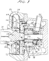
- FIG. 1 shows a cross-sectional view of a liquid-ring pump of the above-mentioned type having a vacuum pump rotor 96 having a plurality of substantially radially extending vanes 98.
- the radially vaned rotor 96 is a one-piece stainless steel construction.
- Rotor 96 is mounted on shaft 58 extending through the vacuum pump housing 78 and being coupled to the shaft of a drive motor (not shown) in known manner.
- the vacuum pump housing is generally covered by a so-called head, a plate-like member sealing the vacuum pump chamber and usually containing the air inlet port end air discharge port therein.
- the head is formed by intermediate plate 72 provided with an air inlet opening 74 and 94, respectively.
- the air outlet port is provided at the opposite side of the vacuum pump chamber at gas discharge opening 80.
- the vacuum pump chamber 76 is thus formed by two opposed end walls 110 and 112 whereby chamber will 112 is part of the intermediate plate 72 in the embodiment shown in FIG. 1, the liquid-ring pump is incorporated into a centrifugal pump for pumping gas containing fiber suspensions in the pulp and paper industry. Accordingly, intermediate plate 72 separates the centrifugal pump volute 54 from the vacuum pump chamber 76.
- a centrifugal impeller 60 is mounted on the end of shaft 58. Impeller 60 has a backplate 64 provided with one or more openings 62 therein for permitting air which has accumulated in front of the impeller to pass therethrough into the area behind the impeller backplate and from there through openings 74 and 94 into the vacuum pump.
- Impeller 60 is also provided with conventional pumping vanes but may also be provided with fluidizing blades extending through centrifugal pump inlet channel 52 and into the pulp containing vessel as schematically indicated at 71.
- the fluidizing blades 71 may also be mounted on a rotor in front of the impeller substantially coaxially with the pump inlet channel to extend only within the pulp containing vessel.
- a rotor comprising one or more rotor vanes 98 in which at least a portion of one radial edge facing one of end walls 110, 112 is tapered so that the axial length of said vane 98 is shorter at the tip thereof (B2) than in the vicinity of the rotor central portion 102 (B1) of the vacuum pump rotor 96.
- This has the affect of decreasing the clearance 108 between the rotor blade and the respective end walls 110, 112 in the direction from the tip of the vane 98 toward the shaft 58. For example, every second vane, all of the vanes or any appropriate number of vanes may be so tapered.
- one or both end walls 110, 112 may be tapered so that the axial distance between the end walls 110, 112 increases from the vicinity or area of the rotor central portion 102 as indicated at B1, in radial direction as indicated at B2 representing the axial length of circumferential vacuum pump chamber wall 100 connecting end walls 110 and 112.
- the clearance 108 between vacuum pump rotor 96 and end walls 110, 112 is increased by the same value irrespective of whether the rotor is tapered outwardly toward the tips thereof or the end walls are tapered inwardly from the circumferential wall toward the rotor central portion.
- the vacuum chamber walls are substantially parallel and perpendicular to the axis of the shaft 58.
- the lateral edge of the vacuum pump rotor vane is preferably maintained susbtantially parallel and perpendicular to the axis of the shaft.
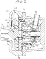
- the centrifugal pump housing 50 is attached to the pump frame 56 having at one end thereof the bearing assembly (not shown) for supporting the pump shaft 58 at the end of which the centrifugal impeller 60 is mounted.
- the centrifugal impeller 60 is further provided with front vanes, i.e. working vanes 66.
- the sealing assembly Located between the bearing unit and the centrifugal impeller 60 is the sealing assembly (not shown).
- Vacuum pump 70 is separated from the volute 54, i.e. from the space housing the centrifugal impeller 60, by means of an intermediate plate 72 which also forms the head of the vacuum pump 70.
- plate 72 has a central annular opening 74 for the shaft 58 and for permitting the gas to flow from the space behind the centrifugal impeller 60 to the vacuum pump 70, as described above.
- the vacuum pump housing 78 has, in addition to the eccentric chamber 76, a discharge port or pipe 80 for the gas connected to the pressure side of the chamber 76 (the upper side in FIG. 3) and leading to a gas discharge connection 82 on the outer surface of the housing.
- the housing 78 further has an additional air duct 84 leading to the eccentric chamber 76 at its suction side (the lower side in FIG. 3) and at the back side of the vacuum pump chamber relative to its front side facing the head or intermediate plate 72.
- Duct 84 is for providing control or make-up air to the vacuum jump 70, i.e. for controlling the vacuum of the pump and for maintaining the vacuum at a constant level. It is to be noted that air duct 84 is dimensioned with respect to its diameter and length so that the vacuum pump 70 will readily receive additional air in case these is insufficient air contained in and separated from the suspension to be pumped. A control valve (not shown) for regulating the vacuum of the vacuum pump may be directly attached to the end of the make-up air duct 84.
- the intermediate plate or head 72 is provided with a relative wide duct 86 for the introduction of a liquid such as flushing water or the like leading from the connection 88 on the vacuum pump housing or body 78 outer surface to a large open volume 90 within the plate and around the shaft 58 of the pump or around the extension sleeve 92 of the impeller 60.
- a liquid such as flushing water or the like leading from the connection 88 on the vacuum pump housing or body 78 outer surface to a large open volume 90 within the plate and around the shaft 58 of the pump or around the extension sleeve 92 of the impeller 60.
- duct 86 is used for introducing a liquid such as water to the vacuum pump 70, for instance for feeding liquid to the liquid ring or for flushing either the vacuum pump 70, the air inlet 74, the open volume 90 and/or the inlet channel 94 to the vacuum pump 70 in case there are solids in these areas of the pump which must be removed to prevent clogging thereof.
- a liquid such as water
Landscapes
- Engineering & Computer Science (AREA)
- Mechanical Engineering (AREA)
- General Engineering & Computer Science (AREA)
- Applications Or Details Of Rotary Compressors (AREA)
- Lubrication Of Internal Combustion Engines (AREA)
- Paper (AREA)
- Rotary Pumps (AREA)
- Reciprocating Pumps (AREA)
Applications Claiming Priority (2)
| Application Number | Priority Date | Filing Date | Title |
|---|---|---|---|
| US579402 | 1990-09-07 | ||
| US07/579,402 US5078573A (en) | 1990-09-07 | 1990-09-07 | Liquid ring pump having tapered blades and housing |
Publications (3)
| Publication Number | Publication Date |
|---|---|
| EP0474476A2 true EP0474476A2 (de) | 1992-03-11 |
| EP0474476A3 EP0474476A3 (en) | 1992-05-06 |
| EP0474476B1 EP0474476B1 (de) | 1995-01-11 |
Family
ID=24316752
Family Applications (1)
| Application Number | Title | Priority Date | Filing Date |
|---|---|---|---|
| EP91308100A Expired - Lifetime EP0474476B1 (de) | 1990-09-07 | 1991-09-04 | Drehpumpe |
Country Status (5)
| Country | Link |
|---|---|
| US (1) | US5078573A (de) |
| EP (1) | EP0474476B1 (de) |
| AT (1) | ATE117052T1 (de) |
| DE (1) | DE69106631T2 (de) |
| ES (1) | ES2067875T3 (de) |
Cited By (1)
| Publication number | Priority date | Publication date | Assignee | Title |
|---|---|---|---|---|
| EP0889242A1 (de) * | 1997-07-04 | 1999-01-07 | GARO Dott.Ing.Roberto Gabbioneta S.p.A. | Flüssigkeitsringverdichter |
Families Citing this family (22)
| Publication number | Priority date | Publication date | Assignee | Title |
|---|---|---|---|---|
| SE467982B (sv) * | 1990-12-19 | 1992-10-12 | Kamyr Ab | Suspensionspump med inbyggd vakuumpump, vilken vakuumpump har variabel kapacitet |
| US5213479A (en) * | 1992-04-09 | 1993-05-25 | The Nash Engineering Company | Liquid ring pumps with improved housing shapes |
| US5534118A (en) * | 1992-08-13 | 1996-07-09 | Mccutchen; Wilmot H. | Rotary vacuum distillation and desalination apparatus |
| US5413466A (en) * | 1993-10-25 | 1995-05-09 | Coltec Industries Inc. | Unified fuel pump assembly |
| DE69511217T2 (de) * | 1994-11-25 | 1999-11-25 | Fujikoki Mfg. Co. Ltd., Tokio/Tokyo | Abflusspumpe |
| PT830511E (pt) * | 1995-06-05 | 2002-04-29 | Sulzer Pumpen Ag | Processo para controlar o funcionamento de uma combinacao de uma bomba centrifuga e uma bomba de vacuo e uma bomba centrifuga de separacao dos gases |
| US5584911A (en) * | 1995-06-15 | 1996-12-17 | Jordan Holding Company | Vapor recovery system with cyclonic separator |
| US6120252A (en) * | 1995-12-27 | 2000-09-19 | Ahlstrom Machinery Corporation | Gas separation control in a centrifugal pump/vacuum pump |
| WO1997048477A1 (en) * | 1996-06-21 | 1997-12-24 | Jordan Holding Company | Return circuit for vapor recovery system |
| DE19847681C1 (de) * | 1998-10-15 | 2000-06-15 | Siemens Ag | Flüssigkeitsringpumpe |
| US6692234B2 (en) | 1999-03-22 | 2004-02-17 | Water Management Systems | Pump system with vacuum source |
| US6405748B1 (en) | 1999-03-22 | 2002-06-18 | David Muhs | Trailer and fuel tank assembly |
| US6390768B1 (en) | 1999-03-22 | 2002-05-21 | David Muhs | Pump impeller and related components |
| US6315524B1 (en) | 1999-03-22 | 2001-11-13 | David Muhs | Pump system with vacuum source |
| JP4617656B2 (ja) * | 2003-10-14 | 2011-01-26 | パナソニック株式会社 | 密閉型圧縮機 |
| US7878768B2 (en) | 2007-01-19 | 2011-02-01 | David Muhs | Vacuum pump with wear adjustment |
| US8998586B2 (en) * | 2009-08-24 | 2015-04-07 | David Muhs | Self priming pump assembly with a direct drive vacuum pump |
| US9879692B2 (en) * | 2012-03-29 | 2018-01-30 | Weir Minerals Europe Limited | Froth pump and method |
| US8979982B2 (en) | 2013-05-01 | 2015-03-17 | Jordan Technologies, Llc | Negative pressure vapor recovery system |
| CA2915631C (en) | 2013-06-21 | 2020-06-02 | Flow Control Llc. | Debris removing impeller backvane |
| WO2020046799A1 (en) * | 2018-08-27 | 2020-03-05 | The Texas A&M University System | High energy density turbomachines |
| US11181325B2 (en) * | 2019-12-23 | 2021-11-23 | Valgroup S.A. | System for the production of molten salt used as a heat transfer medium for a pyrolysis system |
Family Cites Families (10)
| Publication number | Priority date | Publication date | Assignee | Title |
|---|---|---|---|---|
| US2581055A (en) * | 1946-09-03 | 1952-01-01 | W H Martin | Centrifugal pump |
| GB1226960A (de) * | 1967-07-08 | 1971-03-31 | ||
| US3519365A (en) * | 1968-09-30 | 1970-07-07 | Alfred Conhagen | Centrifugal pump |
| FR2264200B1 (de) * | 1974-03-13 | 1978-07-13 | Siemens Ag | |
| IT1073325B (it) * | 1976-10-01 | 1985-04-17 | Worthington Pump | Perfezionamenti alle pompe centrifughe con girante ausiliaria di alimentazione e relative pompe perfezionate |
| US4172694A (en) * | 1977-11-07 | 1979-10-30 | The Nash Engineering Company | Long liquid ring pumps and compressors |
| US4776758A (en) * | 1987-07-06 | 1988-10-11 | Kamyr Ab | Combined fluidizing and vacuum pump |
| FI85751B (fi) * | 1988-06-17 | 1992-02-14 | Ahlstroem Oy | Foerfarande och anordning foer pumpning av tjockt medium. |
| US4877368A (en) * | 1988-11-08 | 1989-10-31 | A. Ahlstrom Corporation | Fluidizing centrifugal pump |
| US4981413A (en) * | 1989-04-27 | 1991-01-01 | Ahlstrom Corporation | Pump for and method of separating gas from a fluid to be pumped |
-
1990
- 1990-09-07 US US07/579,402 patent/US5078573A/en not_active Expired - Lifetime
-
1991
- 1991-09-04 ES ES91308100T patent/ES2067875T3/es not_active Expired - Lifetime
- 1991-09-04 DE DE69106631T patent/DE69106631T2/de not_active Expired - Lifetime
- 1991-09-04 EP EP91308100A patent/EP0474476B1/de not_active Expired - Lifetime
- 1991-09-04 AT AT91308100T patent/ATE117052T1/de not_active IP Right Cessation
Cited By (1)
| Publication number | Priority date | Publication date | Assignee | Title |
|---|---|---|---|---|
| EP0889242A1 (de) * | 1997-07-04 | 1999-01-07 | GARO Dott.Ing.Roberto Gabbioneta S.p.A. | Flüssigkeitsringverdichter |
Also Published As
| Publication number | Publication date |
|---|---|
| DE69106631T2 (de) | 1995-05-18 |
| EP0474476A3 (en) | 1992-05-06 |
| DE69106631D1 (de) | 1995-02-23 |
| EP0474476B1 (de) | 1995-01-11 |
| ATE117052T1 (de) | 1995-01-15 |
| ES2067875T3 (es) | 1995-04-01 |
| US5078573A (en) | 1992-01-07 |
Similar Documents
| Publication | Publication Date | Title |
|---|---|---|
| EP0474476B1 (de) | Drehpumpe | |
| CA2013132C (en) | Pump for and method of separating gas from a fluid to be pumped | |
| US4921400A (en) | Pump and a method of separating gas by such from a fluid to be pumped | |
| CN103124852B (zh) | 离心泵 | |
| JPH0242193A (ja) | 媒質からポンプによって気体を分離する装置 | |
| KR20060015716A (ko) | 개량된 펌프 임펠러 | |
| CA1217173A (en) | Liquid ring vacuum pump for gaseous media | |
| EP0481598B2 (de) | Kreiselpumpe mit Abdichtungsmitteln | |
| US5116198A (en) | Centrifugal pumping apparatus | |
| US5151010A (en) | Combined centrifugal and vacuum pump | |
| US5152663A (en) | Centrifugal pump | |
| RU98100113A (ru) | Способ управления работой системы центробежный насос и вакуумный насос и газоотделяющий центробежный насос | |
| US5209635A (en) | Slurry pump | |
| EP1892419A2 (de) | Konische Zweistufen-Flüssigkeitsringpumpe mit abnehmbarer Stufenkopf-O-Ring-Aufnahmenabe | |
| JP4724610B2 (ja) | ガス分離装置、その前壁及び分離ロータ | |
| EP1121534B1 (de) | Pumpe für papierbrei | |
| EP1088170B1 (de) | Pumpe für papierbrei | |
| EP1415094B1 (de) | Zellstoffpumpe | |
| WO1993011359A1 (en) | Pump with built-in vacuum pump | |
| SU1663234A1 (ru) | Лопастной насос | |
| HK1121796A (en) | Two stage conical liquid ring pump having removable manifold, shims and first and second stage head o-ring receiving boss |
Legal Events
| Date | Code | Title | Description |
|---|---|---|---|
| PUAI | Public reference made under article 153(3) epc to a published international application that has entered the european phase |
Free format text: ORIGINAL CODE: 0009012 |
|
| 17P | Request for examination filed |
Effective date: 19910924 |
|
| AK | Designated contracting states |
Kind code of ref document: A2 Designated state(s): AT DE ES FR GB SE |
|
| PUAL | Search report despatched |
Free format text: ORIGINAL CODE: 0009013 |
|
| AK | Designated contracting states |
Kind code of ref document: A3 Designated state(s): AT DE ES FR GB SE |
|
| 17Q | First examination report despatched |
Effective date: 19930601 |
|
| GRAA | (expected) grant |
Free format text: ORIGINAL CODE: 0009210 |
|
| AK | Designated contracting states |
Kind code of ref document: B1 Designated state(s): AT DE ES FR GB SE |
|
| REF | Corresponds to: |
Ref document number: 117052 Country of ref document: AT Date of ref document: 19950115 Kind code of ref document: T |
|
| EAL | Se: european patent in force in sweden |
Ref document number: 91308100.6 |
|
| REF | Corresponds to: |
Ref document number: 69106631 Country of ref document: DE Date of ref document: 19950223 |
|
| ET | Fr: translation filed | ||
| REG | Reference to a national code |
Ref country code: ES Ref legal event code: FG2A Ref document number: 2067875 Country of ref document: ES Kind code of ref document: T3 |
|
| PLBE | No opposition filed within time limit |
Free format text: ORIGINAL CODE: 0009261 |
|
| STAA | Information on the status of an ep patent application or granted ep patent |
Free format text: STATUS: NO OPPOSITION FILED WITHIN TIME LIMIT |
|
| 26N | No opposition filed | ||
| REG | Reference to a national code |
Ref country code: GB Ref legal event code: 732E |
|
| REG | Reference to a national code |
Ref country code: GB Ref legal event code: IF02 |
|
| REG | Reference to a national code |
Ref country code: FR Ref legal event code: TP |
|
| PGFP | Annual fee paid to national office [announced via postgrant information from national office to epo] |
Ref country code: ES Payment date: 20090922 Year of fee payment: 19 |
|
| PGFP | Annual fee paid to national office [announced via postgrant information from national office to epo] |
Ref country code: GB Payment date: 20090922 Year of fee payment: 19 |
|
| PGFP | Annual fee paid to national office [announced via postgrant information from national office to epo] |
Ref country code: DE Payment date: 20090922 Year of fee payment: 19 |
|
| PGFP | Annual fee paid to national office [announced via postgrant information from national office to epo] |
Ref country code: SE Payment date: 20100914 Year of fee payment: 20 Ref country code: AT Payment date: 20100914 Year of fee payment: 20 |
|
| GBPC | Gb: european patent ceased through non-payment of renewal fee |
Effective date: 20100904 |
|
| REG | Reference to a national code |
Ref country code: FR Ref legal event code: ST Effective date: 20110531 |
|
| REG | Reference to a national code |
Ref country code: DE Ref legal event code: R119 Ref document number: 69106631 Country of ref document: DE Effective date: 20110401 |
|
| PG25 | Lapsed in a contracting state [announced via postgrant information from national office to epo] |
Ref country code: FR Free format text: LAPSE BECAUSE OF NON-PAYMENT OF DUE FEES Effective date: 20100930 Ref country code: DE Free format text: LAPSE BECAUSE OF NON-PAYMENT OF DUE FEES Effective date: 20110401 |
|
| PG25 | Lapsed in a contracting state [announced via postgrant information from national office to epo] |
Ref country code: GB Free format text: LAPSE BECAUSE OF NON-PAYMENT OF DUE FEES Effective date: 20100904 |
|
| PGFP | Annual fee paid to national office [announced via postgrant information from national office to epo] |
Ref country code: FR Payment date: 20091001 Year of fee payment: 19 |
|
| REG | Reference to a national code |
Ref country code: SE Ref legal event code: EUG |
|
| REG | Reference to a national code |
Ref country code: ES Ref legal event code: FD2A Effective date: 20111118 |
|
| PG25 | Lapsed in a contracting state [announced via postgrant information from national office to epo] |
Ref country code: ES Free format text: LAPSE BECAUSE OF NON-PAYMENT OF DUE FEES Effective date: 20100905 |