EP0474097B1 - Einkaufswagen für Selbstbedienungsgeschäfte - Google Patents
Einkaufswagen für Selbstbedienungsgeschäfte Download PDFInfo
- Publication number
- EP0474097B1 EP0474097B1 EP91114362A EP91114362A EP0474097B1 EP 0474097 B1 EP0474097 B1 EP 0474097B1 EP 91114362 A EP91114362 A EP 91114362A EP 91114362 A EP91114362 A EP 91114362A EP 0474097 B1 EP0474097 B1 EP 0474097B1
- Authority
- EP
- European Patent Office
- Prior art keywords
- basket
- rear wall
- child seat
- seat flap
- child
- Prior art date
- Legal status (The legal status is an assumption and is not a legal conclusion. Google has not performed a legal analysis and makes no representation as to the accuracy of the status listed.)
- Expired - Lifetime
Links
- 235000004443 Ricinus communis Nutrition 0.000 claims description 4
- 240000000528 Ricinus communis Species 0.000 claims description 4
- 238000006073 displacement reaction Methods 0.000 claims 1
- 230000005484 gravity Effects 0.000 abstract 1
- 238000000034 method Methods 0.000 abstract 1
- 238000010276 construction Methods 0.000 description 7
- 230000003993 interaction Effects 0.000 description 1
- 239000000463 material Substances 0.000 description 1
- 230000007246 mechanism Effects 0.000 description 1
Images

Classifications
-
- B—PERFORMING OPERATIONS; TRANSPORTING
- B62—LAND VEHICLES FOR TRAVELLING OTHERWISE THAN ON RAILS
- B62B—HAND-PROPELLED VEHICLES, e.g. HAND CARTS OR PERAMBULATORS; SLEDGES
- B62B3/00—Hand carts having more than one axis carrying transport wheels; Steering devices therefor; Equipment therefor
- B62B3/14—Hand carts having more than one axis carrying transport wheels; Steering devices therefor; Equipment therefor characterised by provisions for nesting or stacking, e.g. shopping trolleys
- B62B3/144—Adaptations for transporting children; Mounting of toys for the children
-
- B—PERFORMING OPERATIONS; TRANSPORTING
- B62—LAND VEHICLES FOR TRAVELLING OTHERWISE THAN ON RAILS
- B62B—HAND-PROPELLED VEHICLES, e.g. HAND CARTS OR PERAMBULATORS; SLEDGES
- B62B2202/00—Indexing codes relating to type or characteristics of transported articles
- B62B2202/70—Flowers; Pots; Plants
Definitions
- the invention relates to a shopping cart for self-service shops, which has a shopping cart above a chassis frame supported by swivel castors, the basket rear wall of which can be pivoted inwards and upwards for stacking similar shopping carts, provided in this basket rear wall, lying next to one another, reaching up to or near the lower edge of the basket rear wall Openings for pushing through the legs of a child and with a child seat flap articulated near the lower edge of these openings in the position of use, which can be pivoted out of the level of the rear wall of the basket into the interior of the shopping cart for use.
- Such shopping carts are known from DE-A-3 111 616.
- the openings for pushing through the legs of the child extend approximately from the upper edge of the rear wall of the basket to, for example, half the height of this basket wall.
- the child seat flap is hinged here, which in the stowed position is folded into a position parallel to the level of the pivoting rear wall of the basket and is folded out of this level in the use position in order to provide a seat for the child.
- the child seat flap of this known shopping cart is held by a handlebar arrangement articulated on the lower edge of the pivotable rear wall of the basket, which also serves as the backrest of the child seat.
- Certain shopping carts for example for self-service garden centers, are equipped with baskets of shallow depth, such that a child seat construction of conventional design and the associated mechanisms for returning the child seat to the stowed position in the plane of the pivoting basket rear wall cannot be used.
- the object of the invention is accordingly to design a shopping cart of the type described at the outset for self-service shops in such a way that a safe seat for carrying a child is created at a low shopping cart depth and the stacking of similar shopping carts is not hindered by the child seat construction.
- the child seat flap itself is articulated somewhat above the continuous lower edge of the rear wall of the basket itself, with reference to the position of use of the basket rear wall, the basket rear wall and the child seat flap then arrive when from the rear a similar shopping cart is inserted to produce the stowed position, in an extended position relative to each other and, when this position is reached, finally together in the Basket interior pivoted upwards without the child seat flap falling into the basket interior of the inserted shopping cart.
- the child seat flap also does not get into the interior of the shopping cart of the inserted shopping cart, which otherwise could no longer be separated from the preceding shopping cart. Rather, the nested shopping carts remain separable from each other after the driver bracket or the free, transverse edge of the child seat flap has such a width that it always rests on the upper side edges of the inserted shopping cart.
- a major advantage of the construction of a shopping cart with a shopping cart of shallow depth is that the child seat flap can be folded up from the position of use, in which it rests essentially on the floor of the shopping cart, into the level of the pivoting basket rear wall and then by a simple handle closes the openings in the rear wall of the basket for inserting the legs of a child in such a way that when the shopping trolley is used without the child seat construction, small objects, for example small flower pots, packs and the like, are prevented from falling out through the openings in the rear wall of the basket.
- the grate bars here expediently run in the longitudinal direction on the inside of the basket. These grate bars then enable trouble-free sliding of the transverse free edge of the child seat flap or the crossbar of the carrier bracket.
- a stackable shopping cart for self-service shops is shown schematically in the detail and in dash-dotted lines in FIG.
- a U-shaped chassis frame 2 supported by swivel castors 1 and tapering in the direction of travel, carries on the spars 3 a cart 4, which also tapers in the direction of travel, in a substantially customary form.
- the shopping cart has a relatively small depth.
- the basket rear wall 5 is pivotally mounted on a pivot axis 6 running along its upper edge between the basket side walls in such a way that the basket rear wall 5 can pivot upwards and inwards when a similar shopping trolley is inserted into the basket interior to produce the stowed position, as indicated by the arrow P 1 is indicated.
- two adjacent openings 7 and 8 are provided for pushing through the legs of a child to be carried when shopping, which can take place on a child seat flap 9 lying essentially on the floor of the shopping cart 4.
- the child seat flap 9 has a width approximately corresponding to the distance between the outer edges of the openings 7 and 8. If the child seat flap is folded up around its pivoting bearing near the lower edge of the basket rear wall 5, it can handle the openings 7 and 8 cover so that small items from falling out of the shopping cart are avoided if the shopping cart in question is used without a child being carried.
- Parallel to the lower, continuous lattice bar 10 of the basket rear wall 5 runs at a relatively small distance from this a lattice rod 11 which is bent inwards in the area of the openings 7 and 8 with respect to the position of use of the basket rear wall 5 in the direction of the basket interior and in one Distance d from the plane of the basket rear wall 5 runs parallel to it offset.
- the distance d corresponds approximately to the thickness of the child seat flap 9, so that it can be pivoted without being substantially prevented from pivoting by the bars of the basket rear wall 5 running between the openings 7 and 8.
- the brackets 12, 13 and 14 form a driving bracket arrangement which, when the basket rear wall 5 is pivoted inwards and upwards in the basket interior, abuts the lower bracket 10 of the basket rear wall 5 with the respective bracket leg sections closest to the pivot bearing and then in the extended position relative to it Basket rear wall 5 is carried along with it when the basket rear wall 5 continues its upward pivoting movement.
- the crossbar of the C-bracket 14 in turn takes the child seat flap 9 upwards.
- the basket rear wall 5 When producing the stowed position and pushing together similar shopping trolleys, the basket rear wall 5 first pushes the free transverse edge of the child seat flap 9 and the vertex of the brackets 12 and 13 on the bottom of the shopping cart 4 during its upward pivoting movement and then lifts the entire arrangement out of the brackets 12 to 14 and the child seat flap 9 in the continuation of the pivoting movement on, the basket rear wall 5 and the child seat flap and the carrier bracket arrangement being pivoted substantially in a common plane.
- the sliding of the free edge of the child seat flap or the crossbars on the shopping cart floor is favored by the fact that the grating longitudinal bars 15 are arranged running on the inside of the shopping cart.
- the free transverse edge of the child seat flap 9 is designed as a strip 16 which, as shown at 17, is extended laterally beyond the child seat surface in such a way that the projections 17 against the lateral boundaries of the openings 7 and 8 of the basket rear wall 5 protrude and are supported against the vertical bars located here. In this way, a stop for the child seat flap is created on its sides in the covering position relative to the openings 7 and 8.
- the width of the traverse of the carrier bracket arrangement formed from the brackets 12, 13 and 14 is selected so that it is somewhat smaller than the shopping basket width D at a distance from the rear basket end corresponding to the sum of the basket rear wall height H and the child seat depth T.
- the importance of this dimensioning is that the free transverse edge of the child seat flap and the effective traverse of the carrier bracket arrangement can in no way sink into the basket interior of an inserted shopping cart, so that stacked shopping carts according to the construction according to FIG. 1 remain securely separable.
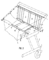
- the embodiment according to FIG. 2 is simplified compared to the construction according to FIG. 1.
- the shopping cart according to FIG. 2 contains a child seat flap 9, in which the side lugs 17 are of a similar design Edge strip 16 are extended so far in the direction of the basket side walls that the edge strip 16 acts overall as a driver, the width of which transversely to the longitudinal direction of the basket is somewhat less than the width of the shopping basket at a distance from the rear end of the basket corresponding to the sum of the basket rear wall height H and child seat flap depth T.
- This dimensioning rule has already been stated in the description of the exemplary embodiment according to FIG. 1.
- the child seat flap 9 is mounted on the basket rear wall 5 at a certain vertical distance with respect to the position of use from the lower rail 10 to the rail 11.
- an offset of the lattice rod 11 can in turn be provided in the direction of the basket interior in order to be able to pivot the child seat flap past the lattice bars of the basket rear wall between the openings 7 and 8.
- the basket rear wall 5 is pivoted upwards, then from a certain pivoting position the lower lattice bar 10 takes it upwards against the underside of the child seat flap 9, the child seat flap 9 being moved essentially lying in the plane of the basket rear wall.
- the lateral projections 17 of the child seat flap 9 are supported on the side edges of the basket and prevent the child seat flap from sinking into the basket interior of the inserted shopping trolley.
- the construction specified here allows the use of plastic child seat flaps that do not extend over the entire width of the basket rear wall, so that plastic material is saved.
- the carrier bracket arrangement comprising the brackets 12, 13 and 14 (see exemplary embodiment according to FIG. 1) can be dispensed with, since the lateral projections 17 of the child seat flap 9 and the interaction of the underside of the child seat flap with the lower lattice bar 10 of the basket rear wall perform the carrier function fulfill.
Landscapes
- Engineering & Computer Science (AREA)
- Chemical & Material Sciences (AREA)
- Combustion & Propulsion (AREA)
- Transportation (AREA)
- Mechanical Engineering (AREA)
- Handcart (AREA)
Description
- Die Erfindung betrifft einen Einkaufswagen für Selbstbedienungsgeschäfte, welcher über einem von Schwenkrollen abgestützten Fahrgestellrahmen einen Warenkorb aufweist, dessen Korbrückwand zur Stapelung gleichartiger Einkaufswagen nach einwärts und aufwärts schwenkbar ist, mit in dieser Korbrückwand vorgesehenen, nebeneinanderliegenden, bis zu oder nahe dem unteren Rand der Korbrückwand reichenden Öffnungen zum Durchstecken der Beine eines Kindes und mit einer nahe dem in der Gebrauchslage unteren Rand dieser Öffnungen angelenkten Kindersitzklappe, die zur Verwendung aus der Ebene der Korbrückwand heraus in den Warenkorbinnenraum hineinschwenkbar ist. Solche Einkaufswagen sind aus der DE-A-3 111 616 bekannt.
- Bei anderen bekannten stapelbaren Einkaufswagen mit Kindersitz an der schwenkbaren Korbrückwand erstrecken sich die Öffnungen zum Durchstecken der Beine des Kindes etwa vom oberen Rand der Korbrückwand bis beispielsweise auf die halbe Höhe dieser Korbwand. Hier ist die Kindersitzklappe angelenkt, welche in der Verstaustellung in eine Position parallel zur Ebene der schwenkbaren Korbrückwand geklappt ist und in der Gebrauchsstellung aus dieser Ebene herausgeklappt wird, um eine Sitzfläche für das Kind zu bieten. In der Gebrauchsstellung wird die Kindersitzklappe dieser bekannten Einkaufswagen durch eine am unteren Rand der schwenkbaren Korbrückwand angelenkte Lenkeranordnung gehalten, welche auch als Rücklehne des Kindersitzes dient.
- Werden bekannte gleichartige Einkaufswagen mit Kindersitz in die Verstaustellung gefahren und ineinandergestapelt, so stößt die Rücklehne des in einen vorausfahrenden Einkaufswagen eingeschobenen, zu stapelnden Einkaufswagens gegen den hinteren Korbrand des vorausfahrenden Einkaufswagens und wird in die Ebene der zugehörigen Korbrückwand gedrückt, wobei gleichzeitig die Kindersitzklappe hochgeklappt wird.
- Bestimmte Einkaufswagen, beispielsweise für Selbstbedienungs-Gartencenters, werden mit Warenkörben geringer Tiefe ausgestattet, derart, daß hier eine Kindersitzkonstruktion herkömmlicher Bauart und die zugehörigen Mechanismen zur Rückführung des Kindersitzes in die Verstaustellung in der Ebene der schwenkbaren Korbrückwand nicht verwendbar sind.
- Aufgabe der Erfindung ist es demgemäß, einen Einkaufswagen der eingangs beschriebenen Art für Selbstbedienungsgeschäfte so auszubilden, daß bei geringer Warenkorbtiefe ein sicherer Sitzplatz zum Mitführen eines Kindes geschaffen wird und das Ineinanderstapeln gleichartiger Einkaufswagen durch die Kindersitzkonstruktion nicht behindert wird.
- Diese Aufgabe wird erfindungsgemäß durch einen Einkaufswagen mit den Merkmalen des Patentanspruches 1 gelöst.
- Eine weitere erfindungsgemäße Lösung ist durch die Merkmale von Patentanspruch 2 verwirklicht.
- Dadurch, daß bei der erstgenannten erfindungsgemäßen Lösung der Mitnehmerbügel, und bei der zweitgenannten Lösung die Kindersitzklappe selbst mit Bezug auf die Gebrauchslage der Korbrückwand etwas oberhalb von deren durchgehendem unteren Rand an der Korbrückwand angelenkt sind, gelangen die Korbrückwand und die Kindersitzklappe dann, wenn von rückwärts ein gleichartiger Einkaufswagen zur Herstellung der Verstaustellung eingeschoben wird, in eine gestreckte Lage relativ zueinander und werden, wenn diese Stellung erreicht ist, schließlich gemeinsam in dem Korbinnenraum aufwärts geschwenkt, ohne daß die Kindersitzklappe in den Korbinnenraum des eingeschobenen Warenkorbes hineinfällt. Beim vollständigen Einschieben des nachfolgenden Einkaufswagens und seines Warenkorbes gelangt die Kindersitzklappe auch nicht in den Innenraum des Warenkorbes des eingeschobenen Einkaufswagens, welcher andernfalls nicht mehr von dem vorausfahrenden Einkaufswagen getrennt werden könnte. Vielmehr bleiben die ineinandergeschobenen Einkaufswagen voneinander wieder trennbar, nachdem der Mitnehmerbügel bzw. der freie, quer verlaufende Rand der Kindersitzklappe solche Breite hat, daß er stets auf den oberen Seitenrändern des eingeschobenen Warenkorbes aufliegt.
- Ein wesentlicher Vorteil der hier angegebenen Konstruktion eines Einkaufswagens mit Warenkorb geringer Tiefe ist es, daß durch einen einfachen Handgriff die Kindersitzklappe von der Gebrauchslage, in der sie im wesentlichen auf dem Boden des Warenkorbes aufliegt, in die Ebene der schwenkbaren Korbrückwand hochgeklappt werden kann und dann die zum Durchstecken der Beine eines Kindes dienenden Öffnungen der Korbrückwand verschließt, derart, daß bei Verwendung des Einkaufswagens ohne Einsatz der Kindersitzkonstruktion ein Herausfallen von kleinen Gegenständen, beispielsweise kleinen Blumentöpfen, Packungen und dergleichen durch die Öffnungen der Korbrückwand vermieden wird.
- Besteht der Boden des Warenkorbes aus einem Gitterrost, so verlaufen zweckmäßig die Roststäbe hier auf der Korbinnenseite in Längsrichtung. Diese Roststäbe ermöglichen dann ein störungsfreies Gleiten des querverlaufenden freien Randes der Kindersitzklappe bzw. des Bügelquersteges des Mitnehmerbügels.
- Nachfolgend werden zwei Ausführungsformen anhand der Zeichnung näher beschrieben. Es stellen dar:
- Fig. 1 eine schematische Teildarstellung eines Einkaufswagens mit schwenkbarer Korbrückwand und Kindersitzklappe in perspektivischer Darstellung und
- Fig. 2 eine gegenüber Figur 1 abgewandelte Raumform des hier angegebenen Einkaufswagens.
- In Figur 1 ist ein stapelbarer Einkaufswagen für Selbstbedienungsgeschäfte im Ausschnitt und in strichpunktierten Linien schematisch angegeben. Ein von Schwenkrollen 1 abgestützter, sich in Fahrtrichtung verjüngender, U-förmiger Fahrgestellrahmen 2 trägt an Holmen 3 einen sich ebenfalls in Fahrtrichtung verjüngenden Warenkorb 4 im wesentlich gebräuchlicher Gestalt. Bei dem gezeigten Ausführungsbeispiel hat der Warenkorb verhältnismäßig geringe Tiefe. Die Korbrückwand 5 ist an einer längs ihres oberen Randes verlaufenden Schwenkachse 6 zwischen den Korbseitenwänden derart schwenkbar gelagert, daß sich die Korbrückwand 5 beim Einschieben eines gleichartigen Einkaufswagens zur Herstellung der Verstaustellung in den Korbinnenraum nach aufwärts und einwärts verschwenken kann, wie durch den Pfeil P 1 angedeutet ist.
- In der Korbrückwand 5 sind zwei nebeneinanderliegende Öffnungen 7 und 8 zum Durchstecken der Beine eines beim Einkauf mitzuführenden Kindes vorgesehen, das auf einer im wesentlichen auf dem Boden des Warenkorbes 4 aufliegenden Kindersitzklappe 9 Platz nehmen kann.
- Die Kindersitzklappe 9 hat bei dem in Figur 1 gezeigten Ausführungsbeispiel eine Breite etwa entsprechend dem Abstand der äußeren Ränder der Öffnungen 7 und 8. Wird also die Kindersitzklappe um ihre Schwenklagerung nahe dem unteren Rand der Korbrückwand 5 hochgeklappt, so vermag sie die Öffnungen 7 und 8 abzudecken, so daß das Herausfallen kleiner Gegenstände aus dem Warenkorb vermieden wird, wenn der betreffende Einkaufswagen verwendet wird, ohne daß ein Kind mitgeführt wird.
- Parallel zu dem unteren, durchgehenden Gitterstab 10 der Korbrückwand 5 verläuft in verhältnismäßig geringem Abstand von diesem ein Gitterstab 11, der im Bereich der Öffnungen 7 und 8 mit Bezug auf die Gebrauchslage der Korbrückwand 5 in Richtung auf den Korbinnenraum nach einwärts abgekröpft ist und in einem Abstand d von der Ebene der Korbrückwand 5 parallel zu dieser versetzt verläuft. Der Abstand d entspricht etwa der Dicke der Kindersitzklappe 9, so daß diese verschwenkt werden kann, ohne durch die zwischen den Öffnungen 7 und 8 verlaufenden Gitterstäbe der Korbrückwand 5 an der Schwenkbewegung wesentlich gehindert zu werden. Diejenigen Abschnitte des Gitterstabes 11, welche im wesentlichen in der Ebene der Korbrückwand 5 verlaufen und an den senkrechten Gitterstäben festgeschweißt sind, dienen zur Lagerung von in Korblängsrichtung langgestreckten, U-förmigen Bügeln 12 und 13, die miteinander durch einen an ihnen jeweils festgeschweißten C-Bügel 14 verbunden sind. Dessen in Querrichtung verlaufende Traverse verläuft unter der Kindersitzklappe 9, wie aus Figur 1 ohne weiteres zu erkennen ist. Die Bügel 12, 13 und 14 bilden eine Mitnehmerbügelanordnung, die, wenn die Korbrückwand 5 in dem Korbinnenraum nach einwärts und aufwärts geschwenkt wird, mit den der Schwenklagerung jeweils naheliegenden Bügelschenkelabschnitten an dem unteren Gitterstab 10 der Korbrückwand 5 anstößt und dann in gestreckter Stellung relativ zur Korbrückwand 5 mit dieser mitgenommen wird, wenn die Korbrückwand 5 ihre Aufwärts-Schwenkbewegung fortsetzt. Die Traverse des C-Bügels 14 nimmt ihrerseits die Kindersitzklappe 9 nach aufwärts mit. Beim Herstellen der Verstaustellung und dem Ineinanderschieben gleichartiger Einkaufswagen schiebt also die Korbrückwand 5 während ihrer Aufwärts-Schwenkbewegung zunächst den freien Querrand der Kindersitzklappe 9 und die Scheitel der Bügel 12 und 13 auf dem Boden des Warenkorbes 4 vorwärts und hebt dann die gesamte Anordnung aus den Bügeln 12 bis 14 und der Kindersitzklappe 9 bei der Fortsetzung der Schwenkbewegung an, wobei die Korbrückwand 5 und die Kindersitzklappe sowie die Mitnehmerbügelanordnung im wesentlichen in einer gemeinsamen Ebene liegend verschwenkt werden. Das Gleiten des freien Kindersitzklappenrandes bzw. der Bügeltraversen auf dem Warenkorbboden wird dadurch begünstigt, daß die Gitterrostlängsstäbe 15 auf der Innenseite des Warenkorbes verlaufend angeordnet werden.
- Bei der in Figur 1 gezeigten Ausführungsform ist der freie Querrand der Kindersitzklappe 9 als eine Leiste 16 ausgebildet, die seitlich, wie bei 17 gezeigt, über die Kindersitzfläche hinaus verlängert ist, derart, daß die Ansätze 17 gegen die seitlichen Begrenzungen der Öffnungen 7 bzw. 8 der Korbrückwand 5 hinausstehen und sich gegen die hier befindlichen senkrechten Gitterstäbe abstützen. Auf diese Weise wird ein Anschlag für die Kindersitzklappe an ihren Seiten in der Abdeckstellung relativ zu den Öffnungen 7 und 8 geschaffen.
- Die Breite der Traverse der aus den Bügeln 12, 13 und 14 gebildeten Mitnehmerbügelanordnung ist so gewählt, daß sie etwas geringer ist, als die Warenkorbbreite D in einem Abstand vom hinteren Korbende entsprechend der Summe der Korbrückwandhöhe H und der Kindersitztiefe T. Die Bedeutung dieser Bemessung ist, daß der freie Querrand der Kindersitzklappe und die wirksame Traverse der Mitnehmerbügelanordnung keinesfalls in den Korbinnenraum eines eingeschobenen Warenkorbes hinabsinken können, so daß ineinandergestapelte Einkaufswagen entsprechend der Konstruktion nach Figur 1 sicher voneinander trennbar bleiben.
- Die Ausführungsform nach Figur 2 ist gegenüber der Konstruktion nach Figur 1 vereinfacht ausgebildet. Der Einkaufswagen nach Figur 2 enthält bei im übrigen ähnlichem Aufbau eine Kindersitzklappe 9, bei der die seitlichen Ansätze 17 der Randleiste 16 in Richtung auf die Korbseitenwände so weit verlängert sind, daß die Randleiste 16 insgesamt als Mitnehmer wirkt, dessen Breite quer zur Korblängsrichtung etwas geringer ist als die Breite des Warenkorbes in einem Abstand vom hinteren Korbende entsprechend der Summe von Korbrückwandhöhe H und Kindersitzklappentiefe T. Die Bedeutung dieser Bemessungsregel ist bei der Beschreibung des Ausführungsbeispiels nach Figur 1 schon angegeben worden.
- Die Kindersitzklappe 9 ist an der Korbrückwand 5 in bestimmtem Vertikalabstand mit Bezug auf die Gebrauchslage von dem unteren Gitterstab 10 an den Gitterstab 11 gelagert. Im Lagerungsbereich kann wiederum eine Kröpfung des Gitterstabes 11 in Richtung auf das Korbinnere hin vorgesehen sein, um die Kindersitzklappe an den Gitterstäben der Korbrückwand zwischen den Öffnungen 7 und 8 vorbeischwenken zu können.
- Wird die Korbrückwand 5 nach einwärts hochgeschwenkt, dann nimmt von einer bestimmten Schwenkstellung ab der untere Gitterstab 10 nach Anlaufen gegen die Unterseite der Kindersitzklappe 9 diese nach aufwärts mit, wobei die Kindersitzklappe 9 im wesentlichen in der Ebene der Korbrückwand liegend bewegt wird. Beim weiteren Einschieben eines nachfolgenden, zu stapelnden Einkaufswagens gleicher Art stützen sich auf dessen Korbseitenrändern die seitlichen Ansätze 17 der Kindersitzklappe 9 ab und verhindern ein Absinken der Kindersitzklappe in den Korbinnenraum des eingeschobenen Einkaufswagens.
- Die vorliegend angegebene Konstruktion gestattet es, Kunststoff-Kindersitzklappen einzusetzen, die sich nicht über die gesamte Breite der Korbrückwand erstrecken, so daß Kunststoffmaterial eingespart wird.
- Bei der Ausführungsform nach Figur 2 kann die Mitnehmerbügelanordnung aus den Bügeln 12, 13 und 14 (siehe Ausführungsbeispiel nach Figur 1) entfallen, da die seitlichen Ansätze 17 der Kindersitzklappe 9 und das Zusammenwirken der Unterseite der Kindersitzklappe mit dem unteren Gitterstab 10 der Korbrückwand die Mitnehmerfunktion erfüllen.
Claims (6)
- Einkaufswagen für Selbstbedienungsgeschäfte, welcher über einem von Schwenkrollen (1) abgestützten Fahrgestellrahmen (2) einen Warenkorb aufweist, dessen Korbrückwand (5) zur Stapelung gleichartiger Einkaufswagen nach einwärts und aufwärts schwenkbar ist, mit in dieser Korbrückwand vorgesehenen, nebeneinanderliegenden, bis zu oder nahe dem unteren Rand der Korbrückwand (5) reichenden Öffnungen (7, 8) zum Durchstecken der Beine eines Kindes und mit einer nahe dem in der Gebrauchslage unteren Rand dieser Öffnungen angelenkten Kindersitzklappe (9), die zur Verwendung aus der Ebene der Korbrückwand heraus in den Warenkorbinnenraum hineinschwenkbar ist, dadurch gekennzeichnet, daß oberhalb des unteren, durchgehenden Randes (10) der Korbrückwand beidseits der Schwenklagerung der Kindersitzklappe (9) und im wesentlichen auf gleicher Höhe an der Korbrückwand (5) eine Mitnehmerbügelanordnung (12, 13, 14) angelenkt ist, deren quer zur Korblängsrichtung orientierter Bügelsteg einerseits größere Breite als die Kindersitzklappe (9) und andererseits geringere Breite als der Warenkorb in einem Abstand vom hinteren Korbende entsprechend der Summe von Korbrückwandhöhe (H) und Kindersitzklappentiefe (T) hat und unter der Kindersitzklappe hindurch verläuft.
- Einkaufswagen für Selbstbedienungsgeschäfte, welcher über einem von Schwenkrollen (1) abgestützten Fahrgestellrahmen (2) einen Warenkorb (4) aufweist, dessen Korbrückwand (5) zur Stapelung gleichartiger Einkaufswagen nach einwärts und aufwärts schwenkbar ist, mit in dieser Korbrückwand vorgesehenen, nebeneinanderliegenden, bis zu oder nahe dem unteren Rand der Korbrückwand (5) reichenden Öffnungen (7, 8) zum Durchstecken der Beine eines Kindes und mit einer nahe dem in der Gebrauchslage unteren Rand dieser Öffnungen angelenkten Kindersitzklappe (9), die zur Verwendung aus der Ebene der Korbrückwand heraus in den Warenkorbinnenraum hineinschwenkbar ist und die etwas oberhalb des unteren durchgehenden Randes (10) der Korbrückwand (5) an dieser angelenkt ist, dadurch gekennzeichnet, daß der vom angelenkten Rand abliegende Rand der Kindersitzklappe als freier Rand ausgebildet ist und insbesondere als Mitnehmer (16, 17) gestaltet ist und eine Breite aufweist, die geringer ist als die Breite des Warenkorbes (4) in einem Abstand vom hinteren Korbende entsprechend der Summe von Korbrückwandhöhe (H) und Kindersitzklappentiefe (T).
- Einkaufswagen nach Anspruch 1 oder 2, dadurch gekennzeichnet, daß die Kindersitzklappe (9) aus Kunststoff besteht.
- Einkaufswagen nach einem der Ansprüche 1 bis 3, dadurch gekennzeichnet, daß die Kindersitzklappe (9) an einem Gitterrohrstab (11) der Korbrückwand (5) gelagert ist, der parallel zu dem unteren Rand (10) der Korbrückwand in geringem Abstand von diesem verläuft und im Bereich der Anlenkung der Kindersitzklappe und der Öffnungen (7, 8) der Korbrückwand in Richtung auf den Korbinnenraum abgekröpft ist und im wesentlichen entsprechend der Dicke (d) der Kindersitzklappe (9) einwärts versetzt verläuft.
- Einkaufswagen nach einem der Ansprüche 1 bis 4, dadurch gekennzeichnet, daß als unterer Rand (10) der Korbrückwand (5) ein Gitterroststab vorgesehen ist, der dazu bestimmt ist, sich beim Hochschwenken der Korbrückwand von unten an die Mitnehmerbügelanordnung bzw. an die Kindersitzklappe anzulegen und eine Verschwenkung dieser Teile beim Hochschwenken der Korbrückwand über eine zu dieser gestreckte Stellung hinaus zu verhindern.
- Einkaufswagen nach einem der Ansprüche 1 bis 5, dadurch gekennzeichnet, daß die Gitterroststäbe (15) des Boden-Gitterrostes des Warenkorbes (4) auf der Korbinnenseite in Längsrichtung verlaufen.
Applications Claiming Priority (2)
| Application Number | Priority Date | Filing Date | Title |
|---|---|---|---|
| DE9012289U DE9012289U1 (de) | 1990-08-27 | 1990-08-27 | Einkaufswagen für Selbstbedienungsgeschäfte |
| DE9012289U | 1990-08-27 |
Publications (2)
| Publication Number | Publication Date |
|---|---|
| EP0474097A1 EP0474097A1 (de) | 1992-03-11 |
| EP0474097B1 true EP0474097B1 (de) | 1995-10-25 |
Family
ID=6856895
Family Applications (1)
| Application Number | Title | Priority Date | Filing Date |
|---|---|---|---|
| EP91114362A Expired - Lifetime EP0474097B1 (de) | 1990-08-27 | 1991-08-27 | Einkaufswagen für Selbstbedienungsgeschäfte |
Country Status (3)
| Country | Link |
|---|---|
| EP (1) | EP0474097B1 (de) |
| AT (1) | ATE129468T1 (de) |
| DE (2) | DE9012289U1 (de) |
Family Cites Families (3)
| Publication number | Priority date | Publication date | Assignee | Title |
|---|---|---|---|---|
| US3645554A (en) * | 1970-05-04 | 1972-02-29 | Unarco Industries | Shopping cart |
| US4116456A (en) * | 1977-05-19 | 1978-09-26 | Unarco Industries, Inc. | Shopping cart |
| DE3111616A1 (de) * | 1980-12-23 | 1982-10-28 | Rudolf Wanzl Kg, 8874 Leipheim | Ineinanderschiebbarer einkaufswagen mit kindersitzanordnung |
-
1990
- 1990-08-27 DE DE9012289U patent/DE9012289U1/de not_active Expired - Lifetime
-
1991
- 1991-08-27 EP EP91114362A patent/EP0474097B1/de not_active Expired - Lifetime
- 1991-08-27 DE DE59106760T patent/DE59106760D1/de not_active Expired - Fee Related
- 1991-08-27 AT AT91114362T patent/ATE129468T1/de not_active IP Right Cessation
Also Published As
| Publication number | Publication date |
|---|---|
| DE9012289U1 (de) | 1991-02-07 |
| ATE129468T1 (de) | 1995-11-15 |
| DE59106760D1 (de) | 1995-11-30 |
| EP0474097A1 (de) | 1992-03-11 |
Similar Documents
| Publication | Publication Date | Title |
|---|---|---|
| DE8812023U1 (de) | Einkaufswagen mit einem an seinem oberen Teil angeordneten Transportkorb | |
| DE2924658A1 (de) | Rollwagen | |
| DE3448335C3 (de) | Stapelbarer Einkaufswagen | |
| EP0141398A2 (de) | Stapelbarer Einkaufswagen | |
| DE8500639U1 (de) | Einkaufswagen für Selbstbedienungsläden mit einer Abstellvorrichtung für Kisten oder dgl. | |
| DE4337917C2 (de) | Stapelbarer Einkaufswagen | |
| DE8508238U1 (de) | Stapelbarer Einkaufswagen | |
| EP0254210B2 (de) | Stapelbarer Einkaufswagen | |
| EP0569988A2 (de) | Transportkarre für unterfahrbare Gegenstände | |
| EP0474097B1 (de) | Einkaufswagen für Selbstbedienungsgeschäfte | |
| DE3208691A1 (de) | Einkaufswagen mit warenablage | |
| EP0683083A2 (de) | Einkaufswagen | |
| DE8136236U1 (de) | Stapelbarer einkaufswagen | |
| EP0609663B1 (de) | Einkaufswagen | |
| EP0751057B1 (de) | Stapelbarer Einkaufswagen | |
| EP0672569A1 (de) | Einkaufswagen | |
| EP0620146B1 (de) | Einkaufswagen | |
| DE8331746U1 (de) | Stapelbarer einkaufswagen | |
| WO1988000148A1 (fr) | Caddie a panier pivotable | |
| DE2505910A1 (de) | Fahrbarer transportbehaelter | |
| DE3233291C2 (de) | ||
| EP0734933B1 (de) | Stapelbarer Einkaufswagen | |
| EP0731011B1 (de) | Einkaufswagen | |
| DE3016282A1 (de) | Klappe fuer koerbe ineinanderzuschachtelnder einkaufwagen fuer selbstbedienungslaeden | |
| DE3909078A1 (de) | Mit entsprechenden wagen schachtelbarer schubgepaeckwagen |
Legal Events
| Date | Code | Title | Description |
|---|---|---|---|
| PUAI | Public reference made under article 153(3) epc to a published international application that has entered the european phase |
Free format text: ORIGINAL CODE: 0009012 |
|
| AK | Designated contracting states |
Kind code of ref document: A1 Designated state(s): AT BE CH DE IT LI LU |
|
| RBV | Designated contracting states (corrected) |
Designated state(s): AT BE CH DE IT LI |
|
| 17P | Request for examination filed |
Effective date: 19920524 |
|
| 17Q | First examination report despatched |
Effective date: 19940429 |
|
| GRAA | (expected) grant |
Free format text: ORIGINAL CODE: 0009210 |
|
| AK | Designated contracting states |
Kind code of ref document: B1 Designated state(s): AT BE CH DE IT LI |
|
| REF | Corresponds to: |
Ref document number: 129468 Country of ref document: AT Date of ref document: 19951115 Kind code of ref document: T |
|
| REF | Corresponds to: |
Ref document number: 59106760 Country of ref document: DE Date of ref document: 19951130 |
|
| REG | Reference to a national code |
Ref country code: CH Ref legal event code: NV Representative=s name: KELLER & PARTNER PATENTANWAELTE AG |
|
| ITF | It: translation for a ep patent filed | ||
| PLBE | No opposition filed within time limit |
Free format text: ORIGINAL CODE: 0009261 |
|
| STAA | Information on the status of an ep patent application or granted ep patent |
Free format text: STATUS: NO OPPOSITION FILED WITHIN TIME LIMIT |
|
| 26N | No opposition filed | ||
| PGFP | Annual fee paid to national office [announced via postgrant information from national office to epo] |
Ref country code: DE Payment date: 20010813 Year of fee payment: 11 |
|
| PGFP | Annual fee paid to national office [announced via postgrant information from national office to epo] |
Ref country code: CH Payment date: 20010824 Year of fee payment: 11 Ref country code: AT Payment date: 20010824 Year of fee payment: 11 |
|
| PGFP | Annual fee paid to national office [announced via postgrant information from national office to epo] |
Ref country code: BE Payment date: 20010912 Year of fee payment: 11 |
|
| PG25 | Lapsed in a contracting state [announced via postgrant information from national office to epo] |
Ref country code: AT Free format text: LAPSE BECAUSE OF NON-PAYMENT OF DUE FEES Effective date: 20020827 |
|
| PG25 | Lapsed in a contracting state [announced via postgrant information from national office to epo] |
Ref country code: LI Free format text: LAPSE BECAUSE OF NON-PAYMENT OF DUE FEES Effective date: 20020831 Ref country code: CH Free format text: LAPSE BECAUSE OF NON-PAYMENT OF DUE FEES Effective date: 20020831 Ref country code: BE Free format text: LAPSE BECAUSE OF NON-PAYMENT OF DUE FEES Effective date: 20020831 |
|
| BERE | Be: lapsed |
Owner name: *BRUDER SIEGEL G.M.B.H. + CO. K.G. DRAHT- UND META Effective date: 20020831 |
|
| PG25 | Lapsed in a contracting state [announced via postgrant information from national office to epo] |
Ref country code: DE Free format text: LAPSE BECAUSE OF NON-PAYMENT OF DUE FEES Effective date: 20030301 |
|
| REG | Reference to a national code |
Ref country code: CH Ref legal event code: PL |
|
| PG25 | Lapsed in a contracting state [announced via postgrant information from national office to epo] |
Ref country code: IT Free format text: LAPSE BECAUSE OF NON-PAYMENT OF DUE FEES;WARNING: LAPSES OF ITALIAN PATENTS WITH EFFECTIVE DATE BEFORE 2007 MAY HAVE OCCURRED AT ANY TIME BEFORE 2007. THE CORRECT EFFECTIVE DATE MAY BE DIFFERENT FROM THE ONE RECORDED. Effective date: 20050827 |