EP0472370A2 - Druckregelvorrichtung - Google Patents
Druckregelvorrichtung Download PDFInfo
- Publication number
- EP0472370A2 EP0472370A2 EP91307553A EP91307553A EP0472370A2 EP 0472370 A2 EP0472370 A2 EP 0472370A2 EP 91307553 A EP91307553 A EP 91307553A EP 91307553 A EP91307553 A EP 91307553A EP 0472370 A2 EP0472370 A2 EP 0472370A2
- Authority
- EP
- European Patent Office
- Prior art keywords
- chamber
- pressure
- control system
- valve
- chambers
- Prior art date
- Legal status (The legal status is an assumption and is not a legal conclusion. Google has not performed a legal analysis and makes no representation as to the accuracy of the status listed.)
- Granted
Links
Images




Classifications
-
- G—PHYSICS
- G05—CONTROLLING; REGULATING
- G05D—SYSTEMS FOR CONTROLLING OR REGULATING NON-ELECTRIC VARIABLES
- G05D16/00—Control of fluid pressure
- G05D16/20—Control of fluid pressure characterised by the use of electric means
- G05D16/2006—Control of fluid pressure characterised by the use of electric means with direct action of electric energy on controlling means
- G05D16/2013—Control of fluid pressure characterised by the use of electric means with direct action of electric energy on controlling means using throttling means as controlling means
- G05D16/2026—Control of fluid pressure characterised by the use of electric means with direct action of electric energy on controlling means using throttling means as controlling means with a plurality of throttling means
- G05D16/2033—Control of fluid pressure characterised by the use of electric means with direct action of electric energy on controlling means using throttling means as controlling means with a plurality of throttling means the plurality of throttling means being arranged in series
-
- G—PHYSICS
- G05—CONTROLLING; REGULATING
- G05D—SYSTEMS FOR CONTROLLING OR REGULATING NON-ELECTRIC VARIABLES
- G05D16/00—Control of fluid pressure
- G05D16/20—Control of fluid pressure characterised by the use of electric means
- G05D16/2006—Control of fluid pressure characterised by the use of electric means with direct action of electric energy on controlling means
- G05D16/2013—Control of fluid pressure characterised by the use of electric means with direct action of electric energy on controlling means using throttling means as controlling means
- G05D16/2026—Control of fluid pressure characterised by the use of electric means with direct action of electric energy on controlling means using throttling means as controlling means with a plurality of throttling means
- G05D16/2046—Control of fluid pressure characterised by the use of electric means with direct action of electric energy on controlling means using throttling means as controlling means with a plurality of throttling means the plurality of throttling means being arranged for the control of a single pressure from a plurality of converging pressures
- G05D16/2053—Control of fluid pressure characterised by the use of electric means with direct action of electric energy on controlling means using throttling means as controlling means with a plurality of throttling means the plurality of throttling means being arranged for the control of a single pressure from a plurality of converging pressures the plurality of throttling means comprising only a first throttling means acting on a higher pressure and a second throttling means acting on a lower pressure, e.g. the atmosphere
-
- G—PHYSICS
- G05—CONTROLLING; REGULATING
- G05D—SYSTEMS FOR CONTROLLING OR REGULATING NON-ELECTRIC VARIABLES
- G05D16/00—Control of fluid pressure
- G05D16/20—Control of fluid pressure characterised by the use of electric means
- G05D16/2006—Control of fluid pressure characterised by the use of electric means with direct action of electric energy on controlling means
- G05D16/2013—Control of fluid pressure characterised by the use of electric means with direct action of electric energy on controlling means using throttling means as controlling means
- G05D16/2026—Control of fluid pressure characterised by the use of electric means with direct action of electric energy on controlling means using throttling means as controlling means with a plurality of throttling means
- G05D16/206—Control of fluid pressure characterised by the use of electric means with direct action of electric energy on controlling means using throttling means as controlling means with a plurality of throttling means the plurality of throttling means being arranged for the control of a plurality of diverging pressures from a single pressure
Definitions
- This invention relates to a system which provides a fluid output regulated to a precisely controlled pressure.
- a fluid pressure control system comprising a chamber, the pressure in which is to be controlled, a pressure source of a pressure different to that required in said chamber and means for supplying at least one discrete pressure step from said source to said chamber whereby to change the pressure in said chamber.
- a fluid pressure control system comprising a first chamber, the pressure in which is to be controlled, a second chamber and means for varying the pressure in said second chamber and then bringing said chambers into communication whereby to change the pressure in said first chamber by at least one discrete pressure step.
- valve means are provided for controlling communication between said chambers, and a controller is arranged such that, if the pressure in the first chamber differs from a desired pressure, said controller,
- the present invention also includes a method of operating a pressure control system to carry out the above steps.
- a pressure transducer 4 is positioned to measure the pressure in the smaller chamber 2 but, when valve 3 is open and the pressures in chambers 1 and 2 equalise, the signal from pressure transducer 4 provides a measurement of the pressure in chamber 1.
- the pressure transducer could be situated in chamber 1 to give a direct, continuous measurement of the pressure in chamber 1.
- Chamber 1 is used to supply fluid through an outlet 5 to operate equipment which is not shown in the drawings but which needs a supply the pressure of which can be controllably varied as required.
- equipment might, typically, be another fluid container which is required to deliver fluid at a defined rate and therefore needs a precisely controlled pressure supply.
- Valve 3 is then closed and fluid from a high pressure source 6 is passed into chamber 2 by the opening of a valve 7.
- the pressure in chamber 2 reaches the inlet pressure of source 6, valve 7 is closed and valve 3 is opened, as described above, discharging a pulse or step of pressure into chamber 1.
- the pressurised supply from source 6 is substantially unregulated and its pressure is higher than the pressure required in chamber 1 but, obviously, lower than that which can be tolerated by the mechanical parts of the system and by the transducer.
- the volume of chamber 2 is relatively small in relation to that of chamber 1, the volumes being in the ratio of about 1:200. This relationship determines the size of the pressure step introduced by each pressure pulse.
- a microprocessor control unit 8 shown diagrammatically, which controls the opening and closing of valves 3 and 7 in response to signals received from the pressure transducer 4.
- the output pressure that is the pressure required in chamber 1, is in the range 5 psi to 65 psi, whilst the inlet pressure is about 70 psi.
- the size of chamber 2 is in the ratio 1:200 to the size of chamber 1.
- the volume of the chambers can be calculated from the above given equation to provide a required precision in the pulses delivered from one chamber to the other.
- FIG. 2 there is shown a fluid pressure regulating system similar to that of Figure 1, in that the system comprises a larger chamber 11 which can be connected to a smaller chamber 12 through a valve 13. If the pressure in the larger chamber 11 falls below a required level, valve 13 is closed and the pressure in chamber 12 is raised to a pressure higher than the pressure required in chamber 11, valve 13 is then opened and the higher pressure of chamber 12 is discharged into chamber 11. As with the system of Figure 1, this pulse or step of pressure increases the pressure in the chamber 11 by a relatively small amount and so a series of such pulses or steps has to be delivered to chamber 11 to increase its pressure up to the required level.
- chamber 11 supplies pressurised fluid to an outlet 15 and chamber 12 can receive high pressure fluid from a source 16 through a valve 17.
- the pressure in the larger chamber 11 can be either incremented by small steps or decremented by small steps.
- valve 13 is closed and valve 19 opened to exhaust chamber 12 to waste through an outlet 18 controlled by valve 19.
- Closing valve 19 and opening valve 13 will then allow fluid to flow from chamber 11 into chamber 12 thus reducing the pressure in chamber 11 by a small amount in accordance with the pressure/volume expression set out above in relation to the arrangement of Figure 1.
- Closing valve 13 and opening valve 19 will exhaust chamber 12 through outlet 18 and further small decrements in the pressure in chamber 11 can then be made by first closing valve 19, opening valve 13 to allow fluid to flow from chamber 11 to chamber 12 and closing valve 13 and opening valve 19 to exhaust chamber 12 to waste again through outlet 18.
- the arrangement shown in Figure 2 also has a third chamber 20 which can be connected through a valve 21 to chamber 12.
- This chamber 20 can be used in conjunction with chamber 12 as follows,
- a microprocessor control unit 22 shown diagrammatically, which controls the opening and closing of valves 13, 17, 19 and 21 in response to signals received from the pressure transducer 4.
- Outlet 18 is usually discharged to atmosphere but, in some applications, it may be preferred to exhaust outlet 18 to a vacuum.
- Figure 3 there is shown a fluid pressure regulating system having the same elements as the systems shown in Figures 1 and 2, in that a larger chamber 31 can be connected to a smaller chamber 32 through a valve 33. If the pressure in the larger chamber 31 falls below a required level, valve 33 is closed and chamber 32 is raised to a pressure which is higher than that required in chamber 31, valve 33 is then opened and the higher pressure of chamber 32 is discharged as a pulse or step into chamber 31. As with the systems of Figures 1 and 2, this pulse of pressure increases the pressure in the larger chamber 31 by a relatively small amount and so a series of such pulses has to be delivered to chamber 31 to increase its pressure up to the required level.
- a pressure transducer 34 is positioned to measure the pressure in the smaller chamber 32 but, when valve 33 is open and the pressures in chambers 31 and 32 equalise, the signal from pressure transducer 34 provides a measurement of the pressure in chamber 31.
- chamber 31 supplies pressurised fluid to an outlet 35 and chamber 32 can receive high pressure fluid from a source 36 through a valve 37.
- Chambers 31 and 32 have the same size relationship as in the system of Figures 1 and 2.
- the system shown in Figure 3 has two fluid outputs.
- the system can provide a second precisely controlled pressure output 45 from a chamber 42 and this can be at a different pressure from the pressure of output 35. If the pressure in the chamber 42 falls below its required level, valve 43 is closed and the pressure in chamber 32 is raised to a pressure which is higher than the pressure required in chamber 42, valve 43 is then opened and the higher pressure of chamber 32 is discharged into chamber 42.
- this pulse or step of pressure increases the pressure in the larger chamber 42 by a relatively small amount and so a series of such pulses has to be delivered to chamber 42 to increase its pressure up to the required level.
- control unit 44 shown diagrammatically, which controls the opening and closing of valves 33, 37, 39, 41 and 43 in response to signals received from the pressure transducer 34.
- the control unit 44 will cause pulses of pressure to be delivered to or removed from these two chambers by interleaving the pulses in whatever the logic of the software of unit 44 deems to be the most efficient manner.
- control units receive information on pressures, volumes and the number of pressure pulses delivered and are able to deduce flow information and can give a read-out of flow rate and total flow.
- the control units are able to select the coarser pulses when a large pressure difference exists and then switch to the finer pulses as the required pressure is neared.
- the control unit can predict the pressure increment or decrement which one pulse will cause, using the pressure/volume relationships set out above, and, when the pressure in the larger chamber is close to the required pressure, it will allow a pulse to be delivered only when the resultant deviation from the required pressure will be a minimum.
- the pressure control systems described here are all simple in construction with few moving parts, mostly just the valves, so that assembly and maintenance is relatively low cost.
- the valves are on-off valves of simple construction.
- the arrangement shown in Figure 3 also has a third chamber 40 which can be connected through a valve 42 to chamber 12.
- This chamber 40 can be used in conjunction with chamber 12 in the same way as described above in relation to Figure 2, to produce coarser or finer control to the production of pulses of pressure.
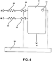
- FIG 4 there is shown a fluid pressure control system comprising a chamber 51 which is used to supply fluid through an outlet 55 to operate equipment, which is not shown in the drawings, but which needs a pressure supply which can be varied as required.
- the pressure in chamber 51 is measured by a transducer 54 which is connected to a microprocessor controller 58.
- controller 58 opens valve 53 to allow a pulse or step of high pressure fluid from a source 56 to flow through a restrictor 59 into the chamber 55 and, if the pressure in chamber 51 is above the required level, controller 58 opens valve 63 to allow a pulse or step of fluid to flow from chamber 51 to exhaust 66 through a restrictor 69.
- the restrictors 59 and 69 restrict the rate of flow into and out of the chamber 51 depending on the pressure difference across them.
- a fluid pressure control system comprising a chamber 71 which is used to supply fluid through an outlet 75 to operate equipment, which is not shown in the drawings, but which needs a supply the pressure of which can be varied as required.
- the pressure in chamber 71 is measured by a transducer 74 which is connected to a controller 78.
- controller 78 opens valve 73 to cause a pulse or step of high pressure fluid from a source 76 to flow through a restrictor 79 into the chamber 71 and, if the pressure in chamber 71 is above the required level, controller 78 opens valve 83 to allow a pulse or step of fluid to flow from chamber 71 to exhaust 86 through the restrictor 79.
- the restrictor 79 restricts the rate of flow into and out of the chamber 71 depending on the pressure difference across it.
- valves 53 and 63 are disposed between their respective restrictors 59, 69 on the one hand and chamber 51 on the other, whereas in the arrangement of Figure 5, the restrictor 79 is disposed between valves 73, 83 on the one hand and chamber 71 on the other.
- the flow through a restrictor which can be likened to a small hole, is dependent on its size and the pressure drop across it and, when pressure is cut off, the pressure drop existing at that time across the restrictor will take a finite time to decay and a small amount of fluid flow will occur until there is no pressure difference across the restrictor.
- valve 73 or valve 83 is shut a small amount of flow continues either into or out of chamber 71 whilst the pressure difference across restrictor 79 decays.
- valve 53 or valve 63 is shut, because the respective valve is positioned next to the chamber 71, flow into or out of chamber 55 will cease immediately.
- Figure 6 shows an arrangement similar to that of Figure 5, of a fluid pressure control system comprising a chamber 81 which is used to supply fluid through an outlet 85 to operate equipment, which is not shown in the drawings, but which needs a supply the pressure of which can be varied as required.
- the pressure in chamber 81 is measured by a transducer 84 which is connected to a controller 88.
- controller 88 opens valve 93 to cause a pulse or step of high pressure fluid from a source 96 to flow through a restrictor 89 into the chamber 81 and, if the pressure in chamber 81 is above the required level, controller 88 opens valve 103 to allow a pulse or step of fluid to flow from chamber 81 to exhaust 106 through the restrictor 89.
- the restrictor 89 varies the rate of flow into and out of the chamber 81 depending on the pressure difference across it.
- an additional valve 97 is arranged between restrictor 89 and chamber 81 and the closing of this valve cuts off flow between restrictor 89 and chamber 81 preventing the decaying flow through the restrictor 89 from causing an overshoot of pressure in the chamber.
- An additional advantage of the arrangement of Figure 6 can be utilised when a large pressure difference below the required pressure exists in chamber 81.
- First valves 93 and 97 can be opened to allow fluid to flow from source 96 to chamber 81 through restrictor 89 until the pressure in chamber 81 nears the required level. Then, provided the restrictor 89 and the system pipework adjacent it have a volume of the order of 1:200 in relation to the volume of chamber 81, the system can be operated in a fashion similar to the operation of the embodiment of Figure 1.
- restrictor 89 and its associated pipework can be supplied with fluid from source 96 with valve 93 open and valve 97 shut.
- valve 93 can be closed and valve 97 opened to allow a pressure pulse or step to be delivered to chamber 81.
- a series of pulses can be delivered to chamber 81 to bring its pressure up to the required level.
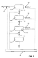
- a fluid pressure control system which comprises a chamber 111 which can be connected to a chamber 112 through a valve 113.
- a pressure transducer 114 is situated in chamber 112 and will indicate the pressure in chamber 111 when valve 113 is open and the pressures have equalised. If the pressure in the chamber 111 falls below a required level, valve 113 is closed and chamber 112 is raised to a pressure higher than the pressure required in chamber 111, valve 113 is then opened and the higher pressure of chamber 112 is discharged into chamber 111. This delivers a pulse or discrete step of pressure into chamber 111 which increases the pressure in chamber 111 by an amount which depends on the pressures then in chambers 111 and 112, as these two chambers are of equal volume.
- Chamber 111 is used to supply fluid through an outlet 115 to operate equipment which is not shown in the drawings but which needs a pressure supply which can be controllably varied as required.
- the pressure supply to chamber 112 comes from a pressure source 116 through a valve 117 and two additional chambers 118 and 119 are connected in the system with valves 120, 121.
- the chambers 111, 112, 118 and 119 may all be of equal volume but are not necessarily equal.
- Chambers 112, 118 and 119 are capable of being exhausted to atmosphere through respective valves 122, 128 and 129.
- Chambers 112, 118 and 119 are used to provide a wide variation in the pressure available in chamber 112 for delivery as a pulse or step to chamber 111.
- valves 117, 121 and 120 can be opened and chambers 112, 118 and 119 all filled to the inlet pressure of source 116.
- valve 117 is closed and valve 113 opened, this will produce a large increase in the pressure in chamber 111, depending on the starting pressure in chamber 111 and its relationship to the pressure in source 116.
- chamber 119 alone can be charged to the inlet pressure of source 116 by keeping valve 121 closed. Then by closing valve 117 and opening valve 121, having first exhausted chamber 118, the pressure in chamber 119 can be equilibriated between chambers 119 and 118 producing a pressure in these two chambers lower than the inlet pressure from source 116. By closing valve 121 the pressure in chamber 118 can be equilibriated between chambers 118 and 112 and a pressure pulse or step of much lower pressure than the inlet pressure from source 116 can delivered to chamber 111.
- chamber 119 alone can be charged to the inlet pressure of source 116 by keeping valve 121 closed. Then by closing valve 117 and opening valve 121, having first exhausted chamber 118, the pressure in chamber 119 can be equilibriated between chambers 119 and 118 producing a pressure in these two chambers lower than the inlet pressure from source 116. By then successively exhausting chamber 118 to atmosphere and equilibriating it with chamber 119, an even lower pressure can be produced.
- the chambers thus act as pressure dividers to produce pulses of pressure which are lower than the pressure of source 116.
- the opening and closing of all the valves are controlled by a control system 108 and, because of the multiplicity of chambers and valves, this control system can be preparing a pulse of a desired pressure in chamber 118 whilst still delivering the previous pulse from chamber 112 to chamber 111.
- pulse and “step” are used. These two terms are used synonymously to mean the delivery of a finite amount of fluid into or out of a chamber.
Landscapes
- Physics & Mathematics (AREA)
- Fluid Mechanics (AREA)
- General Physics & Mathematics (AREA)
- Engineering & Computer Science (AREA)
- Automation & Control Theory (AREA)
- Control Of Fluid Pressure (AREA)
Applications Claiming Priority (2)
| Application Number | Priority Date | Filing Date | Title |
|---|---|---|---|
| GB9018182 | 1990-08-18 | ||
| GB909018182A GB9018182D0 (en) | 1990-08-18 | 1990-08-18 | Pressure regulating system |
Publications (3)
| Publication Number | Publication Date |
|---|---|
| EP0472370A2 true EP0472370A2 (de) | 1992-02-26 |
| EP0472370A3 EP0472370A3 (en) | 1993-06-16 |
| EP0472370B1 EP0472370B1 (de) | 1996-10-23 |
Family
ID=10680894
Family Applications (1)
| Application Number | Title | Priority Date | Filing Date |
|---|---|---|---|
| EP19910307553 Expired - Lifetime EP0472370B1 (de) | 1990-08-18 | 1991-08-15 | Druckregelvorrichtung |
Country Status (4)
| Country | Link |
|---|---|
| EP (1) | EP0472370B1 (de) |
| JP (1) | JPH0689115A (de) |
| DE (1) | DE69122819T2 (de) |
| GB (1) | GB9018182D0 (de) |
Cited By (1)
| Publication number | Priority date | Publication date | Assignee | Title |
|---|---|---|---|---|
| CN109976402A (zh) * | 2019-04-26 | 2019-07-05 | 太原理工大学 | 一种压差自动控制装置及控制方法 |
Families Citing this family (2)
| Publication number | Priority date | Publication date | Assignee | Title |
|---|---|---|---|---|
| FR2827682B1 (fr) * | 2001-07-20 | 2004-04-02 | Gemplus Card Int | Regulation de pression par transfert d'un volume de gaz calibre |
| JP7535461B2 (ja) * | 2021-01-15 | 2024-08-16 | 株式会社堀場エステック | 圧力制御システム、圧力制御方法、及び、圧力制御プログラム |
Family Cites Families (2)
| Publication number | Priority date | Publication date | Assignee | Title |
|---|---|---|---|---|
| US4585030A (en) * | 1984-04-06 | 1986-04-29 | Borg-Warner Corporation | Proportional hydraulic solenoid controller |
| NL8702414A (nl) * | 1987-10-09 | 1989-05-01 | Stork Brabant Bv | Werkwijze en inrichting voor het regelen van de druk in een met gas gevuld vat, in het bijzonder toegepast in een rotatie-drukinrichting. |
-
1990
- 1990-08-18 GB GB909018182A patent/GB9018182D0/en active Pending
-
1991
- 1991-08-15 EP EP19910307553 patent/EP0472370B1/de not_active Expired - Lifetime
- 1991-08-15 DE DE1991622819 patent/DE69122819T2/de not_active Expired - Fee Related
- 1991-08-16 JP JP3229597A patent/JPH0689115A/ja active Pending
Cited By (1)
| Publication number | Priority date | Publication date | Assignee | Title |
|---|---|---|---|---|
| CN109976402A (zh) * | 2019-04-26 | 2019-07-05 | 太原理工大学 | 一种压差自动控制装置及控制方法 |
Also Published As
| Publication number | Publication date |
|---|---|
| GB9018182D0 (en) | 1990-10-03 |
| EP0472370B1 (de) | 1996-10-23 |
| EP0472370A3 (en) | 1993-06-16 |
| DE69122819T2 (de) | 1997-04-03 |
| DE69122819D1 (de) | 1996-11-28 |
| JPH0689115A (ja) | 1994-03-29 |
Similar Documents
| Publication | Publication Date | Title |
|---|---|---|
| US5357996A (en) | Pressure regulating system | |
| CA1064472A (en) | Multi component liquid mixer with accumulator and throttle control | |
| EP0332132B1 (de) | Elektrohydraulisches Steuersystem, insbesondere für Spritzgussmaschinen | |
| US5375634A (en) | Variable mass flow rate fluid dispensing control | |
| US5406988A (en) | Method and apparatus for dispensing compressed gas into a vehicle | |
| US4392514A (en) | Apparatus and method for precision gas mixing | |
| EP1386083B1 (de) | Steuersystem und -verfahren zur steuerung eines stellglieds und zur optimierung der steuerung durch einen satz von parallelgeschalteten ventilen | |
| CN102269152A (zh) | 药液供应系统 | |
| WO1980001797A1 (en) | Precision material filling systems | |
| KR20130100343A (ko) | 공압 액체 분배 장치 및 방법 | |
| WO2007103043A2 (en) | Liquid dispense system | |
| US3847173A (en) | Gas supply system | |
| CA2092065A1 (en) | Sludge pump | |
| EP0472370B1 (de) | Druckregelvorrichtung | |
| JPH01302118A (ja) | 計量供給装置 | |
| CA2086879A1 (en) | Process and apparatus for delivering a metered shot | |
| JPH0829283B2 (ja) | 液体定量吐出装置 | |
| EP1030098B1 (de) | Einspritzverfahren und Vorrichtung zur Odorierung von Gas in einer Pumpstation | |
| JP2517181B2 (ja) | 液体定量吐出装置 | |
| JP2662382B2 (ja) | 液体定量吐出装置 | |
| US4597405A (en) | Process and apparatus for controlling a controllable magnitude and use of the process | |
| EP0265426B1 (de) | Betätigungsvorrichtung für rohrkammer-speiseeinrichtungen hydraulischer förderanlagen | |
| KR100717494B1 (ko) | 유류 출하 시스템 | |
| AU745584B2 (en) | Liquor dispensing apparatus | |
| JPH0665916B2 (ja) | 流量制御弁 |
Legal Events
| Date | Code | Title | Description |
|---|---|---|---|
| PUAI | Public reference made under article 153(3) epc to a published international application that has entered the european phase |
Free format text: ORIGINAL CODE: 0009012 |
|
| AK | Designated contracting states |
Kind code of ref document: A2 Designated state(s): DE ES FR GB IT |
|
| PUAL | Search report despatched |
Free format text: ORIGINAL CODE: 0009013 |
|
| AK | Designated contracting states |
Kind code of ref document: A3 Designated state(s): DE ES FR GB IT |
|
| 17P | Request for examination filed |
Effective date: 19931214 |
|
| 17Q | First examination report despatched |
Effective date: 19950306 |
|
| GRAH | Despatch of communication of intention to grant a patent |
Free format text: ORIGINAL CODE: EPIDOS IGRA |
|
| GRAH | Despatch of communication of intention to grant a patent |
Free format text: ORIGINAL CODE: EPIDOS IGRA |
|
| GRAA | (expected) grant |
Free format text: ORIGINAL CODE: 0009210 |
|
| AK | Designated contracting states |
Kind code of ref document: B1 Designated state(s): DE ES FR GB IT |
|
| PG25 | Lapsed in a contracting state [announced via postgrant information from national office to epo] |
Ref country code: IT Free format text: LAPSE BECAUSE OF FAILURE TO SUBMIT A TRANSLATION OF THE DESCRIPTION OR TO PAY THE FEE WITHIN THE PRE;WARNING: LAPSES OF ITALIAN PATENTS WITH EFFECTIVE DATE BEFORE 2007 MAY HAVE OCCURRED AT ANY TIME BEFORE 2007. THE CORRECT EFFECTIVE DATE MAY BE DIFFERENT FROM THE ONE RECORDED.SCRIBED TIME-LIMIT Effective date: 19961023 Ref country code: ES Free format text: THE PATENT HAS BEEN ANNULLED BY A DECISION OF A NATIONAL AUTHORITY Effective date: 19961023 |
|
| REF | Corresponds to: |
Ref document number: 69122819 Country of ref document: DE Date of ref document: 19961128 |
|
| RAP2 | Party data changed (patent owner data changed or rights of a patent transferred) |
Owner name: OXFORD GLYCOSCIENCES (UK) LIMITED |
|
| ET | Fr: translation filed | ||
| PLBE | No opposition filed within time limit |
Free format text: ORIGINAL CODE: 0009261 |
|
| STAA | Information on the status of an ep patent application or granted ep patent |
Free format text: STATUS: NO OPPOSITION FILED WITHIN TIME LIMIT |
|
| 26N | No opposition filed | ||
| PGFP | Annual fee paid to national office [announced via postgrant information from national office to epo] |
Ref country code: DE Payment date: 20000807 Year of fee payment: 10 |
|
| PGFP | Annual fee paid to national office [announced via postgrant information from national office to epo] |
Ref country code: GB Payment date: 20000809 Year of fee payment: 10 |
|
| PGFP | Annual fee paid to national office [announced via postgrant information from national office to epo] |
Ref country code: FR Payment date: 20000811 Year of fee payment: 10 |
|
| PG25 | Lapsed in a contracting state [announced via postgrant information from national office to epo] |
Ref country code: GB Free format text: LAPSE BECAUSE OF NON-PAYMENT OF DUE FEES Effective date: 20010815 |
|
| GBPC | Gb: european patent ceased through non-payment of renewal fee |
Effective date: 20010815 |
|
| PG25 | Lapsed in a contracting state [announced via postgrant information from national office to epo] |
Ref country code: FR Free format text: LAPSE BECAUSE OF NON-PAYMENT OF DUE FEES Effective date: 20020430 |
|
| PG25 | Lapsed in a contracting state [announced via postgrant information from national office to epo] |
Ref country code: DE Free format text: LAPSE BECAUSE OF NON-PAYMENT OF DUE FEES Effective date: 20020501 |
|
| REG | Reference to a national code |
Ref country code: FR Ref legal event code: ST |