EP0471742B1 - Arrangement in a smoke camouflage system - Google Patents
Arrangement in a smoke camouflage system Download PDFInfo
- Publication number
- EP0471742B1 EP0471742B1 EP90907532A EP90907532A EP0471742B1 EP 0471742 B1 EP0471742 B1 EP 0471742B1 EP 90907532 A EP90907532 A EP 90907532A EP 90907532 A EP90907532 A EP 90907532A EP 0471742 B1 EP0471742 B1 EP 0471742B1
- Authority
- EP
- European Patent Office
- Prior art keywords
- smoke
- screening
- nozzles
- powder
- emitting
- Prior art date
- Legal status (The legal status is an assumption and is not a legal conclusion. Google has not performed a legal analysis and makes no representation as to the accuracy of the status listed.)
- Expired - Lifetime
Links
- 239000000779 smoke Substances 0.000 title claims abstract description 165
- 239000000843 powder Substances 0.000 claims abstract description 80
- 238000012216 screening Methods 0.000 claims abstract description 68
- 239000000463 material Substances 0.000 claims abstract description 57
- 239000000203 mixture Substances 0.000 claims abstract description 24
- 229910001369 Brass Inorganic materials 0.000 claims abstract description 23
- 239000010951 brass Substances 0.000 claims abstract description 23
- 238000003892 spreading Methods 0.000 claims abstract description 23
- 230000007480 spreading Effects 0.000 claims abstract description 20
- 238000007664 blowing Methods 0.000 claims abstract description 16
- 239000002245 particle Substances 0.000 claims abstract description 9
- YKTSYUJCYHOUJP-UHFFFAOYSA-N [O--].[Al+3].[Al+3].[O-][Si]([O-])([O-])[O-] Chemical compound [O--].[Al+3].[Al+3].[O-][Si]([O-])([O-])[O-] YKTSYUJCYHOUJP-UHFFFAOYSA-N 0.000 claims abstract 4
- 238000007865 diluting Methods 0.000 claims abstract 2
- 239000004576 sand Substances 0.000 claims description 20
- GWEVSGVZZGPLCZ-UHFFFAOYSA-N titanium dioxide Inorganic materials O=[Ti]=O GWEVSGVZZGPLCZ-UHFFFAOYSA-N 0.000 claims description 9
- 230000004913 activation Effects 0.000 claims description 7
- BFNBIHQBYMNNAN-UHFFFAOYSA-N ammonium sulfate Chemical compound N.N.OS(O)(=O)=O BFNBIHQBYMNNAN-UHFFFAOYSA-N 0.000 claims description 5
- 229910052921 ammonium sulfate Inorganic materials 0.000 claims description 5
- 235000011130 ammonium sulphate Nutrition 0.000 claims description 5
- MNNHAPBLZZVQHP-UHFFFAOYSA-N diammonium hydrogen phosphate Chemical compound [NH4+].[NH4+].OP([O-])([O-])=O MNNHAPBLZZVQHP-UHFFFAOYSA-N 0.000 claims description 5
- 238000005286 illumination Methods 0.000 claims description 5
- 239000000654 additive Substances 0.000 claims description 4
- 230000000996 additive effect Effects 0.000 claims description 4
- 239000001166 ammonium sulphate Substances 0.000 claims description 3
- 238000004519 manufacturing process Methods 0.000 claims description 3
- 239000007787 solid Substances 0.000 claims description 3
- 238000001228 spectrum Methods 0.000 claims description 3
- 229910000388 diammonium phosphate Inorganic materials 0.000 claims description 2
- 235000019838 diammonium phosphate Nutrition 0.000 claims description 2
- 238000009826 distribution Methods 0.000 claims description 2
- 230000005484 gravity Effects 0.000 claims 3
- XEEYBQQBJWHFJM-UHFFFAOYSA-N Iron Chemical compound [Fe] XEEYBQQBJWHFJM-UHFFFAOYSA-N 0.000 claims 2
- 239000002893 slag Substances 0.000 claims 2
- 239000005995 Aluminium silicate Substances 0.000 claims 1
- 229910001018 Cast iron Inorganic materials 0.000 claims 1
- 229910052782 aluminium Inorganic materials 0.000 claims 1
- XAGFODPZIPBFFR-UHFFFAOYSA-N aluminium Chemical compound [Al] XAGFODPZIPBFFR-UHFFFAOYSA-N 0.000 claims 1
- 229910000323 aluminium silicate Inorganic materials 0.000 claims 1
- 235000012211 aluminium silicate Nutrition 0.000 claims 1
- 239000012530 fluid Substances 0.000 claims 1
- 239000003365 glass fiber Substances 0.000 claims 1
- 229910052742 iron Inorganic materials 0.000 claims 1
- 239000010450 olivine Substances 0.000 claims 1
- 229910052609 olivine Inorganic materials 0.000 claims 1
- TWNQGVIAIRXVLR-UHFFFAOYSA-N oxo(oxoalumanyloxy)alumane Chemical compound O=[Al]O[Al]=O TWNQGVIAIRXVLR-UHFFFAOYSA-N 0.000 claims 1
- 238000003860 storage Methods 0.000 claims 1
- 239000003570 air Substances 0.000 description 26
- 238000000034 method Methods 0.000 description 7
- 238000012360 testing method Methods 0.000 description 7
- 230000008033 biological extinction Effects 0.000 description 6
- 235000015842 Hesperis Nutrition 0.000 description 5
- 235000012633 Iberis amara Nutrition 0.000 description 5
- 238000010521 absorption reaction Methods 0.000 description 5
- 239000002184 metal Substances 0.000 description 5
- 229910052751 metal Inorganic materials 0.000 description 5
- 230000000694 effects Effects 0.000 description 4
- 239000007788 liquid Substances 0.000 description 4
- 229920000914 Metallic fiber Polymers 0.000 description 3
- 239000000835 fiber Substances 0.000 description 3
- 239000000945 filler Substances 0.000 description 3
- 239000013528 metallic particle Substances 0.000 description 3
- 241000220317 Rosa Species 0.000 description 2
- LSNNMFCWUKXFEE-UHFFFAOYSA-N Sulfurous acid Chemical compound OS(O)=O LSNNMFCWUKXFEE-UHFFFAOYSA-N 0.000 description 2
- 239000012080 ambient air Substances 0.000 description 2
- 230000005540 biological transmission Effects 0.000 description 2
- 230000001419 dependent effect Effects 0.000 description 2
- 239000000428 dust Substances 0.000 description 2
- BWHMMNNQKKPAPP-UHFFFAOYSA-L potassium carbonate Chemical compound [K+].[K+].[O-]C([O-])=O BWHMMNNQKKPAPP-UHFFFAOYSA-L 0.000 description 2
- 230000008569 process Effects 0.000 description 2
- 230000005855 radiation Effects 0.000 description 2
- 239000011435 rock Substances 0.000 description 2
- 238000001429 visible spectrum Methods 0.000 description 2
- XLYOFNOQVPJJNP-UHFFFAOYSA-N water Substances O XLYOFNOQVPJJNP-UHFFFAOYSA-N 0.000 description 2
- VXEGSRKPIUDPQT-UHFFFAOYSA-N 4-[4-(4-methoxyphenyl)piperazin-1-yl]aniline Chemical compound C1=CC(OC)=CC=C1N1CCN(C=2C=CC(N)=CC=2)CC1 VXEGSRKPIUDPQT-UHFFFAOYSA-N 0.000 description 1
- NLXLAEXVIDQMFP-UHFFFAOYSA-N Ammonium chloride Substances [NH4+].[Cl-] NLXLAEXVIDQMFP-UHFFFAOYSA-N 0.000 description 1
- VHUUQVKOLVNVRT-UHFFFAOYSA-N Ammonium hydroxide Chemical compound [NH4+].[OH-] VHUUQVKOLVNVRT-UHFFFAOYSA-N 0.000 description 1
- UIIMBOGNXHQVGW-UHFFFAOYSA-M Sodium bicarbonate Chemical class [Na+].OC([O-])=O UIIMBOGNXHQVGW-UHFFFAOYSA-M 0.000 description 1
- RTAQQCXQSZGOHL-UHFFFAOYSA-N Titanium Chemical compound [Ti] RTAQQCXQSZGOHL-UHFFFAOYSA-N 0.000 description 1
- 206010070863 Toxicity to various agents Diseases 0.000 description 1
- 239000002253 acid Substances 0.000 description 1
- 239000000443 aerosol Substances 0.000 description 1
- 235000011114 ammonium hydroxide Nutrition 0.000 description 1
- -1 caolin Substances 0.000 description 1
- 238000006243 chemical reaction Methods 0.000 description 1
- 238000004040 coloring Methods 0.000 description 1
- 230000006378 damage Effects 0.000 description 1
- 238000005474 detonation Methods 0.000 description 1
- 238000011161 development Methods 0.000 description 1
- 238000010586 diagram Methods 0.000 description 1
- 239000012895 dilution Substances 0.000 description 1
- 238000010790 dilution Methods 0.000 description 1
- 238000011156 evaluation Methods 0.000 description 1
- 230000002349 favourable effect Effects 0.000 description 1
- 238000012840 feeding operation Methods 0.000 description 1
- 238000010304 firing Methods 0.000 description 1
- 230000009969 flowable effect Effects 0.000 description 1
- 239000000446 fuel Substances 0.000 description 1
- 239000007789 gas Substances 0.000 description 1
- 238000002329 infrared spectrum Methods 0.000 description 1
- ZLNQQNXFFQJAID-UHFFFAOYSA-L magnesium carbonate Chemical compound [Mg+2].[O-]C([O-])=O ZLNQQNXFFQJAID-UHFFFAOYSA-L 0.000 description 1
- 239000001095 magnesium carbonate Substances 0.000 description 1
- 229910000021 magnesium carbonate Inorganic materials 0.000 description 1
- 230000007246 mechanism Effects 0.000 description 1
- 239000003921 oil Substances 0.000 description 1
- 229910000027 potassium carbonate Inorganic materials 0.000 description 1
- 238000002360 preparation method Methods 0.000 description 1
- 230000035484 reaction time Effects 0.000 description 1
- 231100000812 repeated exposure Toxicity 0.000 description 1
- 239000005049 silicon tetrachloride Substances 0.000 description 1
- 235000017557 sodium bicarbonate Nutrition 0.000 description 1
- 230000002269 spontaneous effect Effects 0.000 description 1
- 239000000454 talc Substances 0.000 description 1
- 229910052623 talc Inorganic materials 0.000 description 1
- 239000010936 titanium Substances 0.000 description 1
- 229910052719 titanium Inorganic materials 0.000 description 1
- OGIDPMRJRNCKJF-UHFFFAOYSA-N titanium oxide Inorganic materials [Ti]=O OGIDPMRJRNCKJF-UHFFFAOYSA-N 0.000 description 1
- 238000012549 training Methods 0.000 description 1
- 230000001960 triggered effect Effects 0.000 description 1
- 230000000007 visual effect Effects 0.000 description 1
Images


Classifications
-
- F—MECHANICAL ENGINEERING; LIGHTING; HEATING; WEAPONS; BLASTING
- F41—WEAPONS
- F41H—ARMOUR; ARMOURED TURRETS; ARMOURED OR ARMED VEHICLES; MEANS OF ATTACK OR DEFENCE, e.g. CAMOUFLAGE, IN GENERAL
- F41H9/00—Equipment for attack or defence by spreading flame, gas or smoke or leurres; Chemical warfare equipment
- F41H9/06—Apparatus for generating artificial fog or smoke screens
Definitions
- the present invention concerns an arrangement in a smoke camouflage system, preferably for camouflaging and/or screening point targets on fortresses, air parts etc, especially against attacking precisely guided weapons.
- the invention especially concerns a suggestion of how to achieve an effective discharge of screening smoke, especially composition ratios and what kind of nozzles and driving devices to use for the most effective multispectral screening.
- the invention concerns the location of nozzles, trigging such nozzles, and guiding the screening smoke in dependence of meteorological parameters.
- EP 0108939 concerns a launching device comprising packed metallic powder in the launching canister itself.
- the contents of the canister is dispersed through a detonation, and the effect of the powder charge comprising lamellated powder, will be reduced because the spreading rate is less for pure metallic powder alone.
- EP 0108939 specifies that the exhaust gasses from the fuel for the launching canisters aids in blowing out the metallic powder, but such a spontaneous blowout can not be compared to contiuous blowout from a pressure nozzle, as is the case with the present invention.
- Norwegian patent NO.C-58.725 concerns a process for producing smoke over sea, on land or in the air, and specifies a pure liquid being mixed with ambient air giving rise to smoke, something which is without interest in connection with nozzle-spreading of "cold-flowing" metallic powder for IR-screening and metalfibre/dipoles for mm-wave-screening.
- Norwegian patent NO-C-59.443 concerns a process for developing smoke by using a smoke-producing liquid, and represents a further development of the above-mentioned document, NO-C-58.725, but gives no further information about the pure liquid which is to be mixed with the ambient air other than this being added colouring powder.
- the technique relating to this patent is thus scarcely suited for metallic particles, and nothing is specified about the production of a good "cold-flowing" powder composition.
- GB 2000575 specifies a metal pressure cylinder expelling a metal powder composition, more specifically micro-fine powder with a particle diameter from 3 to 60 ⁇ m for estabishing a fog-like cloud for covering a target visually.
- the suggested powder is talc, caolin, potassium carbonate, magnesium carbonate, sodium hydrogen carbonates and other free-flowing powders or powders which have been made flowable, and which may produce a hanging cloud when being spread.
- metallic particles or dipoles being equipped with a siutable carrier, e.g. a sand-blowing composition which in its turn produces a "cold-flowing" composition giving the advantages being specified for the present invention.
- DE 3714454 specifies a two-component fog, especially comprising silicon tetrachloride and an ammonia-solution being suited for smoke-coverage rehearsals and giving a purely visual protection.
- this publication give any specification about how one may suitably discharge a powder charge which has added thereto a suitable filler by using high-pressure nozzles to produce a disperse composition of metallic powder for IR-screening and metallic fibres/dipoles for mm-wave screening.
- the known system is based on the production of a fog by liquids being misted through a stream of pressurised air, and this pressure is far less than what is needed for the present invention wherein the pressure may be compared to what is used for a sand-blowing technique, i.e. in the range of 5-7 bars.
- DE 492806 also concerns a technique wherein there is produced a fog by using sulphurous acid and moist air, there being required two pressure cylinders, namely a first pressure container for the sulphurous acid and a second pressure container for moist pressurised air. This is different from the present system where the feeding may take place directly from a magazine containing the smoke material composition, and where the dosing only is dependent on this smoke material composition alone.
- DE 657353 concerns a fog-generating apparatus comprising a container holding both fog moisture and pressurised gas, as opposed to what is suggested according to the present invention being based on a separate supply of pressurised air and a separate dosing of the present special smoke-powder composition.
- FR-A-2.562.231 discloses a device in a smoke screening system comprising a plurality of high pressure nozzles for emitting one or more spreading clouds.
- this document does not disclose how a suitable additive material could be mixed with the smoke powder charge itself, nor does it suggest that this additive material could contribute to increased reliability in the feeding operation and increased efficiency as regards the spreading of the smoke or cloud.
- the main idea of the invention is based on a siutable powder material composition for multispectral smoke screening from spreading nozzles driven with compressed air, and the whole concept is thus based on mixing a suitable additive material in the smoke powder charge proper.
- a filler e.g. a sand blowing material
- a smoke powder charge which may be a mixture of metallic powder for IR screening (3-14 ⁇ m) and metallic fibres/dipoles for mm-wave screening (e.g. 35-48 GHz) being blown out through nozzles by using high-pressurized air, are disclosed in the following.
- the feeding may be performed (without the use of movable parts) directly from the magazine containing the smoke material mixture.
- the system may be operated contiuously, without operators, where only the magazine capacity limits the operating time.
- the wind speed increases the consumption of smoke material will however increase.
- the magazine will thus become empty more quickly under such conditions if it is not replenished during the operation.
- brass powder for IR-screening different types may show varying degrees of adhesion towards the filler material which may be grains of sand.
- the grains of sand having a high weight/surface area ratio (as opposed to the metallic powder in the form of flakes) will be flung significantly further from the nozzle than the brass flakes.
- the brass flakes will become “peeled off” from the grains of sand during their flight with a consequently greater spreading of the flakes.
- the succeeding grains of sand will also, due to the turbulence effect, "push" the cloud of dust further away from the nozzle. This effect is especially prevalent when there is no wind or little wind. (At a greater wind velocity the wind will also contribute to a "post-spreading" of the cloud.)
- the dilution of the smoke powder will also reduce the size of the powder agglomerates in the air and thus achieve a greater screening effect per weight unit of smoke material. This is due to a more effective splitting up of the powder (the part that is not adhered to the grains) in the nozzle opening when the powder concentration in the air current is reduced.
- Figure 1 shows an outlined suggestion for a smoke system for screening objects, e.g. guns.
- Figure 2 shows a flow diagram for transport of pressurized air and smoke material to the nozzles.
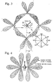
- Figure 3 shows an example of locating four smoke points around a tower gun with four spread clouds of smoke in each smoke point.
- Figure 4 shows an example of locating two smoke points where the terrain makes the locating of several smoke points with a greater spreading difficult.
- Figure 5 shows an illustration of the law of Lanbert-Beer, cfr. equation (4.1).
- Figure 6 shows the smoke material concentration, C, in a homogenous cloud of smoke as a function of the extinction coefficient ⁇ ( ⁇ ) to stop 95% of the incoming radiation towards a cloud with a depth of 16 m.
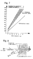
- Figure 8 shows the reflection and absorption of a laser beam with a depth of 16 m as a function of the extinction coefficient, ⁇ ( ⁇ ), of the brass-powder smoke.
- a complete smoke system should further comprise two subsystems, namely one for the warning of an attack and one for producing smoke.
- the present system is based on pressurized air blowing smoke material out through immobile smoke points on the ground.
- a smoke point may consist of several nozzles blowing smoke in given directions.
- Each object or gun which is to be protected has a system of smoke points protecting against attack from all directions.
- the system should comprise elements giving a reaction time in the order of 5-10 s from activation to complete smoke screening.
- the screening should start at a cmparatively early point of time in the attack phase, based on a somewat more uncertain information aboout air attack.
- the following warning systems or combinations thereof should accordingly be of interest:
- laser detectors may automatically activate the corresponding smoke system.
- Smoke screening based on warning by airplane radar from planes and/or observation posts in the terrain, must be performed for example through firing leading officers giving orders for smoke-screening before a possible attack is expected to be initiated. In this case windward smoke points are activated. The concentration of smoke will be "correctly" adjusted according to the wind conditions through a dosage valve being directed by a device measuring the wind velocity.
- the area over which the guns inside a fortress are spread, will be relatively large compared to the smoke area necessary for hiding a gun.
- the screening object will thus be the guns and not the fortress itself.
- Too much smoke may give an unwanted marking of the fortress and also give disturbances on one's own sensors. As a consequence thereof each gun ought to have its own smoke system.
- the smoke screening system should therefore produce a screening aerosol through the spreading of a smoke material.
- a suitable smoke material will be present in the form of dust or powder.
- the activation of of the system may thus be done either automatically or manually. All other functions are to be performed via automations.
- a compressor 1, figure 1 may continuously idle in the alert period. If it is found advantageous, the pressurized air from the compressor 1 will be stripped for water and oil in the filter unit 2, figure 1.
- smoke points 6 which may be armoured, see Figure 2 (see also Figure 3 and Figure 4).
- nozzles with different emitting directions.
- the nozzles are supplied with air and smoke powder through pipes in the rock from the dosage system 3, Figure 1.
- each smoke point there are advantageously at least four nozzles.
- each pipeline will serve two nozzles (only in exceptional cases one nozzle). These nozzle pairs may then be activated idependently frm each other frm the controlling valves 3, Figure 1. The function of these valves is described in detail in connection with Figure 2.
- valves 21, 23 and 25, Figure 2 are opened.
- the valve 21 opens for the pressurized air from the compressor.
- the valve 23 is chronometrically controlled and gives a high pressure in the container for the smoke material for rapid feeding of the nozzles during start.
- the valve 25 is adjusted automatically for a high dosage via signals from the controlling unit 9, Figure 1.
- the valve 23 closes, Figure 2.
- the valve 25 is adjusted for a maintainance dosage. This is adjusted according to maximum wind speed based on signals from a wind measuring apparatus 10, Figure 1.
- the pressurized air passes valve 22 alone, Figure 2, and the nozzle pressure is thereby reduced.
- the system will be turned on when the gun is illuminated by a laser beam.
- the laser warner 7, Figure 1 registers that the gun is illuminated and from which direction the illumination originates. This gives signals to the controlling unit 9, Figure 1, which initiates the starting procedure for the nozzle system giving smoke screening in the angle sector (90-120°) covering the laser illumination independently from the wind direction. If the wind has the same direction as the incoming laser beam, the wind will blow the smoke cloud towards the gun which after a little while will be surrounded by smoke. The feeding of the activated nozzles will thereafter be reduced and the system will go into operation modus.
- Correct dosage will be adjusted accrding to a smoke cloud with an effective depth equal to the distance from the smoke front to the gun, and having a concentration (added a safety margin on account of inhomogenity) sufficient for effective screening. This means that the shorther distance between the gun and the cloud front (in this case the smoke points) the lager dosage is necessary fr achieving screening at a given wind speed. Dosage quantities are discussed later in this disclosure.
- the smoke material may be spread from nozzles being situated in four spreading points (smoke points) A, B, C and D, see Figure 3, about the gun.
- a suggestion for a spreading plan with a nozzled arrangement and a compass rose is also shown in the Figure. If it is operated with four nozzles simultaneously, each smooke point ought to operate with two supply conduits with a regulation valve 25, Figure 2, on each supply conduit.
- point A the nozzles A2 and A3 will be connected to one conduit, and the nozzles A1 and A4 to the other.
- Which nozzles to connect will depend on the direction of the wind. For example with a wind direction between 325° and 375° (cfr. the compass rose in Fig.
- the nozzles A2, A3, B1 and B4 will be activated.
- a wind direction between 375° and 25° will signify activation of all four nozzles in point A.
- the four nozzles giving best cover between rocket and cannon will be activated irrespective of the direction of the wind.
- the smoke emittance will be altered to the four nozzles lying upwind. Based on the fewest possible nozzles under simultaneous operation, one will probably be able to achieve an acceptable level concerning consumption of smoke material and pressurized air.
- a distribution of smoke points as shown in Figure 3 will probably not be feasible in steep hills/cliffs close to the guns. (If one is not to place the smoke points on high stands above the ground with a correspondingly increased vulnerability.) The terrain will then determine the situation of the smoke points. The number of smoke points, distance between the points and the gun, number of nozzles per smoke point and their emitting direction, will then be parameters which may be varied to achieve acceptable coverage from all directions.
- An example of a smoke system with only two smoke points being situated close to the cannon is sketched in Figure 4.
- the probability for an IR-homing rocket to obtain targetting of an object screened by a smoke cloud is dependent on the target-seeking device, the target contrast, K, (against the background), and the ratio of emitted irrdiation from the target getting through the smoke screen (T1/T0).
- the requirement for screening is that the target contrast K being registered by the targetting device through the cloud of smoke is less or equal to a limit value K g , i.e. K ⁇ K g .
- the extinction coefficient ⁇ ( ⁇ ) for brass powder will not only vary between the types. Also the spreading method will give a variation in ⁇ ( ⁇ ).
- the brass powder consists of metal flakes with a diameter of 3-10 ⁇ m and a thickness of 0,1-0,5 ⁇ m. After spreading the flakes will be grouped in small agglomerates with warying diameters. The greater the splitting during the emittance the more effective IR-screening per weight unit of smoke material. Maximum screening efficiency is achieved if all the metal flakes are separated when airborne.
- the transmission rate in IR (8-12 ⁇ m) is 5% and establishment time 10 s.
- the front of the smoke cloud is 16 m from the cannon.
- the bottom curve specifies the quantity for a homogenous cloud of smoke (i.e. the minimum quantity). Within the marked area the probable practical quantity will lie (i.e. inhomogenous spreading).
- Figure 7 thus shows that a blown quantity of smoke material per second at wind velocities up to 8 m/s (being the limiting requirement) is very large.
- L the distance from the gun to the front of the smoke cloud
- the emitted quantity per second may be reduced.
- CA Coast Artillery
- CA-gun is irradiated by laser through a thin cloud of metallic powder (transparent in the visible spectrum).
- the laser beam becomes thereby weakened both through reflection and absorption in the path forth and back through the smoke cloud.
- Figure 8 shows the reflection and absorption of a laser beam when illuminating an attack target being covered by a smoke cloud.
- a rocket will home on reflected laser energy either from the smoke cloud or from the gun.
- the rocket may home upon the reflected irradiation from the target getting through after the cloud (absorption), see Figure 8.
- T1 0,15T0.
- Albedo for a brass powder cloud is approx. 0,15.
- T3 0,15T0.
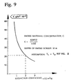
- the curve in figure 9 shows the smoke material concentration, C, in a smoke cloud with a depth of 16 m, as a function of the extinction coefficient, ⁇ ( ⁇ ), of the brass powder cloud.
- ⁇ ( ⁇ ) is 2 m2/g.
- the equipment which was used is a common sand-blowing apparatus, type SEV-25, attatched to a high-pressure compressor (capacity: 20 m3/min expelled air quantity at 20 bars).
- Titanium oxide was used for lack of the suggested rehersal smoke charge based on a mixture of ammonium sulphate and ammonium hydrogen phosphate.
- compositions of active screening materials with suitable quantities of inert solid particles with good cold-flowing properties as more closely generalized and defined in the attatched patent claims.
- a mixture of sand + brass powder will give a screening in the visible range and IR-range.
- a mixture of sand + brass powder + mm-Chaff will give a screening in the visible range, IR- and mm-wave range up to 10-15 mm.
- a mixture of sand + a specially developed screening material + for instance TiO2 will give a screening in the visible range, IR- and mm-wave range.
Landscapes
- Engineering & Computer Science (AREA)
- General Engineering & Computer Science (AREA)
- Filtering Of Dispersed Particles In Gases (AREA)
- Aerodynamic Tests, Hydrodynamic Tests, Wind Tunnels, And Water Tanks (AREA)
- Alarm Systems (AREA)
- Respiratory Apparatuses And Protective Means (AREA)
- Chimneys And Flues (AREA)
- Nozzles (AREA)
Abstract
Description
- The present invention concerns an arrangement in a smoke camouflage system, preferably for camouflaging and/or screening point targets on fortresses, air parts etc, especially against attacking precisely guided weapons.
- The invention especially concerns a suggestion of how to achieve an effective discharge of screening smoke, especially composition ratios and what kind of nozzles and driving devices to use for the most effective multispectral screening.
- More specifically, the invention concerns the location of nozzles, trigging such nozzles, and guiding the screening smoke in dependence of meteorological parameters.
- EP 0108939 concerns a launching device comprising packed metallic powder in the launching canister itself. The contents of the canister is dispersed through a detonation, and the effect of the powder charge comprising lamellated powder, will be reduced because the spreading rate is less for pure metallic powder alone.
- It is true that EP 0108939 specifies that the exhaust gasses from the fuel for the launching canisters aids in blowing out the metallic powder, but such a spontaneous blowout can not be compared to contiuous blowout from a pressure nozzle, as is the case with the present invention.
- Norwegian patent NO.C-58.725 concerns a process for producing smoke over sea, on land or in the air, and specifies a pure liquid being mixed with ambient air giving rise to smoke, something which is without interest in connection with nozzle-spreading of "cold-flowing" metallic powder for IR-screening and metalfibre/dipoles for mm-wave-screening.
- Norwegian patent NO-C-59.443 concerns a process for developing smoke by using a smoke-producing liquid, and represents a further development of the above-mentioned document, NO-C-58.725, but gives no further information about the pure liquid which is to be mixed with the ambient air other than this being added colouring powder. The technique relating to this patent is thus scarcely suited for metallic particles, and nothing is specified about the production of a good "cold-flowing" powder composition.
- GB 2000575 specifies a metal pressure cylinder expelling a metal powder composition, more specifically micro-fine powder with a particle diameter from 3 to 60 µm for estabishing a fog-like cloud for covering a target visually. The suggested powder is talc, caolin, potassium carbonate, magnesium carbonate, sodium hydrogen carbonates and other free-flowing powders or powders which have been made flowable, and which may produce a hanging cloud when being spread. However, there is not given any specification of the problems concerning the expelling of metallic powders, metallic particles not being mentioned at all, and even less the publication specifies metallic particles or dipoles being equipped with a siutable carrier, e.g. a sand-blowing composition which in its turn produces a "cold-flowing" composition giving the advantages being specified for the present invention.
- Admittedly, there is suggested a pressure cylinder and a kind of "environmentally friendly" powder which after use fertilizes the ground, but there is no specification concerning nozzle-spreading of metallic powder for IR-screening (3-12 µm) and metallic fibres/dipoles for mm-wave screening (35-94 GHz) being blown through nozzles by using high-pressure air and with a simple automatical or manual dosing.
- DE 3714454 specifies a two-component fog, especially comprising silicon tetrachloride and an ammonia-solution being suited for smoke-coverage rehearsals and giving a purely visual protection. However, neither does this publication give any specification about how one may suitably discharge a powder charge which has added thereto a suitable filler by using high-pressure nozzles to produce a disperse composition of metallic powder for IR-screening and metallic fibres/dipoles for mm-wave screening. The known system is based on the production of a fog by liquids being misted through a stream of pressurised air, and this pressure is far less than what is needed for the present invention wherein the pressure may be compared to what is used for a sand-blowing technique, i.e. in the range of 5-7 bars.
- DE 492806 also concerns a technique wherein there is produced a fog by using sulphurous acid and moist air, there being required two pressure cylinders, namely a first pressure container for the sulphurous acid and a second pressure container for moist pressurised air. This is different from the present system where the feeding may take place directly from a magazine containing the smoke material composition, and where the dosing only is dependent on this smoke material composition alone.
- DE 657353 concerns a fog-generating apparatus comprising a container holding both fog moisture and pressurised gas, as opposed to what is suggested according to the present invention being based on a separate supply of pressurised air and a separate dosing of the present special smoke-powder composition.
- FR-A-2.562.231 discloses a device in a smoke screening system comprising a plurality of high pressure nozzles for emitting one or more spreading clouds. However, this document does not disclose how a suitable additive material could be mixed with the smoke powder charge itself, nor does it suggest that this additive material could contribute to increased reliability in the feeding operation and increased efficiency as regards the spreading of the smoke or cloud.
- What signifies the present invention is apparent from the attached claims.
- As appearing from the patent claims the main idea of the invention is based on a siutable powder material composition for multispectral smoke screening from spreading nozzles driven with compressed air, and the whole concept is thus based on mixing a suitable additive material in the smoke powder charge proper.
- The advantages being achieved by mixing a filler (e.g. a sand blowing material) into a smoke powder charge which may be a mixture of metallic powder for IR screening (3-14 µm) and metallic fibres/dipoles for mm-wave screening (e.g. 35-48 GHz) being blown out through nozzles by using high-pressurized air, are disclosed in the following.
- i) By adding e.g. a sand blowing material into the smoke powder charge, there is achieved an excellent "cold-flowing" of the powder cmposition. Thereby it is relatively simple to construct a robust and reliable feeding (automatic) mechanism (without movable parts when a setting has been performed) giving an optimal smoke material feeding of the nozzles, based on signals from measuring apparatuses for the wind speed. There is avoided the use of hoppers which are necessary for feeding/dosing the active undiluted smoke material, e.g. a metallic powder/fibre mixture.
- The feeding may be performed (without the use of movable parts) directly from the magazine containing the smoke material mixture. In other words, the system may be operated contiuously, without operators, where only the magazine capacity limits the operating time. When the wind speed increases the consumption of smoke material will however increase. The magazine will thus become empty more quickly under such conditions if it is not replenished during the operation.
- To construct a corresponding feeding automation for the undiluted smoke material will probably not be possible, or will at best represent very large problems. One has then to work with a non-flowing powder (metallic powder/fibre) and with a volume quantity of only a tenth to a fifth of the volume quantity of the preferred "easy-flowing" smoke powder composition. One must here thus use more narrow passages in the dosage system. A problem will be a very variable feeding on account of the "non-flowing"property of the metallic powder, and likewise that the fibre/dipole-component for mm-wave screening may block the relatively narrow passages.
- ii) If there is used brass powder for IR-screening, different types of the powder may show varying degrees of adhesion towards the filler material which may be grains of sand. The grains of sand having a high weight/surface area ratio (as opposed to the metallic powder in the form of flakes) will be flung significantly further from the nozzle than the brass flakes. By choosing brass powder with a suitable adhesion, the brass flakes will become "peeled off" from the grains of sand during their flight with a consequently greater spreading of the flakes. The succeeding grains of sand will also, due to the turbulence effect, "push" the cloud of dust further away from the nozzle. This effect is especially prevalent when there is no wind or little wind. (At a greater wind velocity the wind will also contribute to a "post-spreading" of the cloud.)
- iii) The dilution of the smoke powder will also reduce the size of the powder agglomerates in the air and thus achieve a greater screening effect per weight unit of smoke material. This is due to a more effective splitting up of the powder (the part that is not adhered to the grains) in the nozzle opening when the powder concentration in the air current is reduced.
- The invention is disclosed in greater detail in the following description, the contents of which are given on the next page, and which describes different embodiments of the invention.
- Figure 1 shows an outlined suggestion for a smoke system for screening objects, e.g. guns.
- Figure 2 shows a flow diagram for transport of pressurized air and smoke material to the nozzles.
- Figure 3 shows an example of locating four smoke points around a tower gun with four spread clouds of smoke in each smoke point.
- Figure 4 shows an example of locating two smoke points where the terrain makes the locating of several smoke points with a greater spreading difficult.
- Figure 5 shows an illustration of the law of Lanbert-Beer, cfr. equation (4.1).
- Figure 6 shows the smoke material concentration, C, in a homogenous cloud of smoke as a function of the extinction coefficient α(λ) to stop 95% of the incoming radiation towards a cloud with a depth of 16 m.
- Figure 7 shows the weight quantity of smoke material (α(λ) = 2 m²/g) blown per second as a function of wind speed (emitted smoke from nozzles lying on the "wind side" of the gun) to establish a cloud of smoke covering an area of 200 m².
- Figure 8 shows the reflection and absorption of a laser beam with a depth of 16 m as a function of the extinction coefficient, α(λ), of the brass-powder smoke.
- In the following there will be disclosed different embodiments of the present device for a smoke-screening system. In such a system there are inter alia made the following requirements.
- a) The smoke system is to maintain, with a large degree of probability (>90%) in a wind strength of up to 8 m/s across the direction of attack, an effective smoke screen between incoming rocket/laser designator and the gun, in the last phase of the flight time of the rocket, approx. 10-15 s.
- b) Point 1) is also to be fulfilled if two or more rockets from different directions simultaneously are on their way towards the gun (the fortress).
- c) The smoke screen is to protect against laser-guided, TV-guided and advanced picture-forming IR-target seekers.
- d) The smoke system may be used for training in times of peace with a smoke material which is environmentally acceptable.
- e) The smoke system may in its entirety be operated from protected quarters.
- f) The vulnerability of the smoke system towards any air attack should be equal or less than for the gun itself. (Even if the gun is out of commission the smoke system should still be able to be used as a decoy to suggest the gun's apparent combat value.)
- g) The smoke should be least apparent in the visible and infra-red wave spectrum.
- A complete smoke system should further comprise two subsystems, namely one for the warning of an attack and one for producing smoke.
- The present system is based on pressurized air blowing smoke material out through immobile smoke points on the ground.
- The rest of the system is protected in rock. A smoke point may consist of several nozzles blowing smoke in given directions. Each object or gun which is to be protected, has a system of smoke points protecting against attack from all directions.
- The system should comprise elements giving a reaction time in the order of 5-10 s from activation to complete smoke screening.
- Thus, the screening should start at a cmparatively early point of time in the attack phase, based on a somewat more uncertain information aboout air attack. The following warning systems or combinations thereof should accordingly be of interest:
- i) Laser detector mounted on the gun.
- ii) Detectionn of incoming attacking planes through a suitable radar system. If the fortress has an air-raid radar, this may be used as well.
- iii) Placing of observation posts on strategically chosen locations, on the perimeter or outside the defence area of the fortress.
- By laser illumination of a gun, laser detectors may automatically activate the corresponding smoke system.
- Smoke screening based on warning by airplane radar from planes and/or observation posts in the terrain, must be performed for example through firing leading officers giving orders for smoke-screening before a possible attack is expected to be initiated. In this case windward smoke points are activated. The concentration of smoke will be "correctly" adjusted according to the wind conditions through a dosage valve being directed by a device measuring the wind velocity.
- The area over which the guns inside a fortress are spread, will be relatively large compared to the smoke area necessary for hiding a gun. The screening object will thus be the guns and not the fortress itself. Thus, it is avoided that too much smoke is emitted. Too much smoke may give an unwanted marking of the fortress and also give disturbances on one's own sensors. As a consequence thereof each gun ought to have its own smoke system.
- The smoke screening system should therefore produce a screening aerosol through the spreading of a smoke material. A suitable smoke material will be present in the form of dust or powder. The activation of of the system may thus be done either automatically or manually. All other functions are to be performed via automations.
- Suggestions for a smoke system concept are outlined in figure 1 and 2.
- Referring to Figure 1 and 2 there will in the following de given a description of the functions of the system.
- A
compressor 1, figure 1, may continuously idle in the alert period. If it is found advantageous, the pressurized air from thecompressor 1 will be stripped for water and oil in thefilter unit 2, figure 1. - Around the
gun 8 there are situatedsmoke points 6 which may be armoured, see Figure 2 (see also Figure 3 and Figure 4). In these smoke points there are munted nozzles with different emitting directions. The nozzles are supplied with air and smoke powder through pipes in the rock from thedosage system 3, Figure 1. In each smoke point there are advantageously at least four nozzles. - In most cases each pipeline will serve two nozzles (only in exceptional cases one nozzle). These nozzle pairs may then be activated idependently frm each other frm the controlling
valves 3, Figure 1. The function of these valves is described in detail in connection with Figure 2. - When starting up the system, the
valves valve 21 opens for the pressurized air from the compressor. Thevalve 23 is chronometrically controlled and gives a high pressure in the container for the smoke material for rapid feeding of the nozzles during start. Simultaneously the valve 25 is adjusted automatically for a high dosage via signals from the controllingunit 9, Figure 1. When a covering smoke cloud has been estabished (during 5-10 s), thevalve 23 closes, Figure 2. Simultaneously the valve 25 is adjusted for a maintainance dosage. This is adjusted according to maximum wind speed based on signals from awind measuring apparatus 10, Figure 1. During operation the pressurized air passesvalve 22 alone, Figure 2, and the nozzle pressure is thereby reduced. When stopping the system themanual operating unit 11, Figure 1, is adjusted, andvalves 21 and 25, Figure 2, are being closed. - At automatic activation the system will be turned on when the gun is illuminated by a laser beam. The
laser warner 7, Figure 1, registers that the gun is illuminated and from which direction the illumination originates. This gives signals to the controllingunit 9, Figure 1, which initiates the starting procedure for the nozzle system giving smoke screening in the angle sector (90-120°) covering the laser illumination independently from the wind direction. If the wind has the same direction as the incoming laser beam, the wind will blow the smoke cloud towards the gun which after a little while will be surrounded by smoke. The feeding of the activated nozzles will thereafter be reduced and the system will go into operation modus. Correct dosage will be adjusted accrding to a smoke cloud with an effective depth equal to the distance from the smoke front to the gun, and having a concentration (added a safety margin on account of inhomogenity) sufficient for effective screening. This means that the shorther distance between the gun and the cloud front (in this case the smoke points) the lager dosage is necessary fr achieving screening at a given wind speed. Dosage quantities are discussed later in this disclosure. - Assuming that the wind direction is towars the incoming laser beam, automatic activation will still connect the same nozzles as mentioned previously. In this case the wind lead the smoke cloud away from the gun. This will thereby not be surrounded by the smoke. The wind
direction registering apparatus 10, Figure 1, registeres this fact and activates to operation modus that nozzle system which is lying upwind. After a short period the previously activated system which was triggered by the laser beam, is thus disconnected. The upwind nozzle system will tereafter take over the smoke screening of the cannon. By manual activation this nozzle system will be activated directly. - During a pre-combatting it is not to be disregarded that our air defence fails and that the enemy via areal weapons will go into a preparative attack of the fortress. This may concievably be carried out inter alia to clear away camuflage and possible dummies which are not sufficiently sturdy. Registration equipment such as laser warners and wind measuring equipment may also be put out of commission during this preparation. By total destruction, i.e. when the back-up systems have been destroyed as well, the operating unit for the smoke system will automatically give a signal about this. The smoke system may then only be activated manually. The nozzles may in this emergency situation be controlled by the latest registered wind data. If wanted/necessary one may also prepare the possibility for supplying manually the operating unit with assumed data for wind speed and direction. However, the connection points for the laser warners and wind measuring equipment must be so sufficiently robust and simple that personnell may go out between the attacks to easily replace them if required.
- Concerning the vulnerability of the disclosed smoke system this may according to the claim relatively readily be made less than the gun itself.
- When choosing smoke material for use in battle this must exhibit an acceptable screening capability both in the visible and the infra red spectrum. To avoid a too strong marking of the fortress, the smoke should additionally as much as possible to coincide with the surroundings in the two spectra. Brass powder as a smoke material will to an acceptable degree fulfill these requirements. This smoke is cold and will thus only give a weak signal in IR. In the visible spectrum the smoke will gainst a background of clear fields or sea appear relatively weakly (brownish colour). During winter this should neither be a problem since the situation of most coastal fortifications usually represents a terrain being partly covered by snow.
- An inadvertent inhalation of brass powder gives no toxic symptoms. How repeated exposures over time will affect personnell and environment is uncertain. It is thus recommended that the smoke material only exceptionally is used during practice in peace time. Instead, one should use a material which may be emitted through the original nozzles without using extra equipment. The material must further not give any acid reaction with water. It must additionally be environmentally acceptable. Powder which fulfill these requirements and which is recommended used is:
- ammonium sulphate ((NH₄)₂SO₄)
- ammonium hydrogen phosphate ((NH₄)₂HPO₄)
- Initially the smoke material may be spread from nozzles being situated in four spreading points (smoke points) A, B, C and D, see Figure 3, about the gun. A suggestion for a spreading plan with a nozzled arrangement and a compass rose is also shown in the Figure. If it is operated with four nozzles simultaneously, each smooke point ought to operate with two supply conduits with a regulation valve 25, Figure 2, on each supply conduit. For example in Figure 3, point A, the nozzles A₂ and A₃ will be connected to one conduit, and the nozzles A₁ and A₄ to the other. Which nozzles to connect will depend on the direction of the wind. For example with a wind direction between 325° and 375° (cfr. the compass rose in Fig. 3) the nozzles A₂, A₃, B₁ and B₄ will be activated. A wind direction between 375° and 25° will signify activation of all four nozzles in point A. Upon laser warning during an attack with laser-guided rockets, the four nozzles giving best cover between rocket and cannon will be activated irrespective of the direction of the wind. However, after a short period the smoke emittance will be altered to the four nozzles lying upwind. Based on the fewest possible nozzles under simultaneous operation, one will probably be able to achieve an acceptable level concerning consumption of smoke material and pressurized air.
- A distribution of smoke points as shown in Figure 3, will probably not be feasible in steep hills/cliffs close to the guns. (If one is not to place the smoke points on high stands above the ground with a correspondingly increased vulnerability.) The terrain will then determine the situation of the smoke points. The number of smoke points, distance between the points and the gun, number of nozzles per smoke point and their emitting direction, will then be parameters which may be varied to achieve acceptable coverage from all directions. An example of a smoke system with only two smoke points being situated close to the cannon is sketched in Figure 4.
-
- When evaluating the smoke system concept it will be informative to know approximately what quantities of brass powder which must be emitted per time unit to give a covering smoke screen. A sufficiently good estimate may be done by using the so-called Lambert-Beer's Law:

- C:
- the concentration of smoke material (g/m³) (homogenous smoke cloud)
- L:
- distance of irradiation through the cloud (m)
- α:
- extinction coefficient (m²/g)
- T₁/T₀:
- ratio between irradiation intensities, see Figure 5.
- According to experience it is difficult to presume that screening occurs when T₁/T₀ ≦ 0,05, i.e. when:

- In the following concentrations of smoke material in smoke clouds for screening against laser- and IR-homing rockets is more throughly evaluated.
- The probability for an IR-homing rocket to obtain targetting of an object screened by a smoke cloud is dependent on the target-seeking device, the target contrast, K, (against the background), and the ratio of emitted irrdiation from the target getting through the smoke screen (T₁/T₀). The requirement for screening is that the target contrast K being registered by the targetting device through the cloud of smoke is less or equal to a limit value Kg, i.e. K ≦ Kg.
- The contrast may be expressed by the equation:


- SM :
- The radiance (W/sr.M²) from the target object
- SB :
- The radiance from the background
- SSK:
- The radiance from the smoke cloud (diffracted/re flected sun radiation)
- K₀ :
- Target contrast without smoke
- In this very crude estimate of the cncentration of the smoke material equation (4.2) may be used directly. If it is presumed that the irradiation distance through the cloud is 16 m one will find the following relation when substituting in equation (4.2):

- The extinction coefficient α(λ) for brass powder will not only vary between the types. Also the spreading method will give a variation in α(λ). The brass powder consists of metal flakes with a diameter of 3-10 µm and a thickness of 0,1-0,5 µm. After spreading the flakes will be grouped in small agglomerates with warying diameters. The greater the splitting during the emittance the more effective IR-screening per weight unit of smoke material. Maximum screening efficiency is achieved if all the metal flakes are separated when airborne.
- In figure 6 the required powder concentration for 95% absorption/spreading or IR-radiation through a cloud with a depth of 16 m is specified as a function of the extinction coefficient α(λ), see equation (4.5).
- In a homogenous cloud of smoke which for instance is 40m wide, 5 m high and 16 m deep, it will totally be necessary with 300 g brass powder (α(λ) = 2 m²/g) to reduce the transmission to 5%. This means that theoretically it must be blown out 30g powder per second (evenly dispersed over 200 m²) if the requirement for establishment time is 10 s. (In practice this quantity must be increased , maybe to double the amount on account of uneven spreading.) The condition is that the emittance of brass powder takes place on that side of the gun which is upwind, with a wind velocity of 1,6 m/s (i.e. the wind blows the powder towards the gun, and during 10 s the wanted cloud depth of 16 m will be achieved). If the wind velocity is greater, then the emitted material quantity must increase proportionally with the wind velocity. A simple curve showing this relationship is shown in Figure 7.
- Figure 7 shows the weight quantity of smoke material (α(λ) = 2 m²/g) blown per second as a function of the wind velocity (smoke emitted from nozzles lying "windside" of the cannon) to establish a smoke cloud with a coverage area of 200 m². The transmission rate in IR (8-12 µm) is 5% and establishment time 10 s. The front of the smoke cloud is 16 m from the cannon. The bottom curve specifies the quantity for a homogenous cloud of smoke (i.e. the minimum quantity). Within the marked area the probable practical quantity will lie (i.e. inhomogenous spreading).
- Figure 7 thus shows that a blown quantity of smoke material per second at wind velocities up to 8 m/s (being the limiting requirement) is very large. By increasing the distance, L, from the gun to the front of the smoke cloud, the emitted quantity per second may be reduced. In other words, on Coast Artillery (CA) forts where it is relatively often strong wind, the nozzles ought, if possible, not to be situated too close to the gun.
- As disclosed initially laser-guided weapons with ground-situated dsignators are the most serious threat both today and still some years to come. Smoke-screening against these weapons will be treated in the following.
- One may contemplate that a CA-gun is irradiated by laser through a thin cloud of metallic powder (transparent in the visible spectrum). The laser beam becomes thereby weakened both through reflection and absorption in the path forth and back through the smoke cloud. This is illustrated in Figure 8 showing the reflection and absorption of a laser beam when illuminating an attack target being covered by a smoke cloud. A rocket will home on reflected laser energy either from the smoke cloud or from the gun.
- The rocket may home upon the reflected irradiation from the target getting through after the cloud (absorption), see Figure 8.
- To get an understanding about the concentration range for a smoke screen meant to screen for laser homing, one may calculate the concentration giving T₁ = T₃, Figure 8. To achieve coverage the smoke material concentration must, however, be larger than the value giving T₁ = T₃.
- According to information from USA T₁ = 0,15T₀. Albedo for a brass powder cloud is approx. 0,15.

- From equation (4.1) one finds:

- It is here presupposed that the depth of the smoke cloud, L, is 16 m. The equations (4.8) and (4.9) give

- The curve in figure 9 shows the smoke material concentration, C, in a smoke cloud with a depth of 16 m, as a function of the extinction coefficient, α(λ), of the brass powder cloud. A realistic value for α(λ) is 2 m²/g. The curve specifies the concentration where reflected laser energy in the front of the smoke cloud equals the reflected energy which the rocket will receive from the cannon, i.e. T₁ = T₃, cfr. figure 8. This leads to a smoke material concentration of 20 mg/m³ (or 1/4 of the smoke material concentration for IR-screening, figure 5). To achieve screening in practice it is probable that this concentration must be increased with a factor of 1,5-2, corresponding to 30-40 mg/m³.
- To find the emitted smoke quantity per second as a function of wind speed for laser screening, the values found from the curve on figure 7 for IR-screening may be used. These values must, however, be reduced with approx. 75% to lead to the concentrations corresponding to the equation (4.10).
- There have been performed preliminary tests of emitting powder charges. The equipment which was used is a common sand-blowing apparatus, type SEV-25, attatched to a high-pressure compressor (capacity: 20 m³/min expelled air quantity at 20 bars).
- There were effected tests with brass powder and titanium oxyde, TiO₂, for simulating rehersal smoke. Titanium oxide was used for lack of the suggested rehersal smoke charge based on a mixture of ammonium sulphate and ammonium hydrogen phosphate.
- When emitting pure brass powder the range oof the powder cloud was unacceptably short for all nozzles. In addition there was too poor "flow" in the powder resulting in an uneven feeding to the nozzle (one had to shake the fedding container). To alleviate these problems the brass powder was mixed with a sand-blowing material in the ratio 1:10 and 1:6. The result was that the range of the blown powder cloud increased considerably (30-40 m). In addition there was achieved good flow of the powder with an even feeding to the nozzle.
- At one of the tests with a first type of a nozzle the smoke charge was fed relatively quickly into the nozzle. Air pressure and -flow was 5-6 bars and 3,0-3,4 m³/min, respectively.
- When testing with another nozzle there was used a ratio of brass powder/sand blowing material of 1:6. Air pressure and flow was 5-6 bars and 6,0-7,3 m³/min, respectively. The result was a smoke cloud (after finished blowing) which probably still would screen effectively against laser illumination and IR-homing.
- When testing with a third nozzle the mixture ratio powder/sand was equal to 1:10. Air pressure and flow was 6-8 bars and 6,5-7,5 m³/min, respectively.
- The explanation for the greater range being achieved with the addition of grains of sand into the powder, is probably that metal powder flakes being absorbed/adhered to the grains of sand (initial velocity approx. 350 km/h) "peels" off in the air. In addition flakes being already airborne will be "sucked" along by the turbulence from following grains of sand.
- The spreading of TiO₂ was also tested with addition of grains of sand in the ratio 1:10.
- The wind during the tests was very weak with a direction "inclined" against the emitting direction. The spreading was thus performed under relatively favourable conditions.
- It is to be understood that there might also be used other compositions of active screening materials with suitable quantities of inert solid particles with good cold-flowing properties as more closely generalized and defined in the attatched patent claims.
- Thus a mixture of sand + brass powder will give a screening in the visible range and IR-range. A mixture of sand + brass powder + mm-Chaff will give a screening in the visible range, IR- and mm-wave range up to 10-15 mm.
- A mixture of sand + a specially developed screening material + for instance TiO₂ will give a screening in the visible range, IR- and mm-wave range.
Claims (12)
- Device in a smoke screening system, preferably for camouflaging and/or screening at a singular target (8) on fortresses, airports or similar, especially against attacking precision guided weapons comprising preferably high-pressure nozzles for emitting one or more spreading clouds,
characterised in that said one or more preferably high-pressure nozzles are adapted for emitting screening smoke comprising active screening materials in the form of one or more types of metallic powders, preferably brass powder, to which there is added a material of inter alia inert solid particles with good cold-flowing properties, e.g. aluminium silicate particles and/or a sand blowing material. - Device according to claim 1,
characterised in that the active screening materials may be a metallic powder, preferably brass powder, for screening in the IR-range 3-12 µm, and/or mm-Chaff which may be aluminum-coated glass-fibre needles with a length distribution which especially gives a simultaneous screening both in the 36 GHz range and in the 94 GHz range, or an additive which simultaneously gives a screening both in the IR-range and the mentioned spectra in the mm-wave range, possibly combined with a powder, e.g. Ti0₂, increasing the screening in the visible range, and where there simultaneously in all said mixtures is used inert solid particles with good cold-flowing properties, e.g. particles of aluminum silicate, for diluting and improving the cold-flowing properties of the active smoke charge composition. - Device according to claims 1 or 2,
characterised in that the screening smoke comprises a mixture of metallic powder or brass power and a sand blowing material in the range from about 1:2 to 1:5. - Device according to each of the claims 1-3,
characterised in that the sand blowing material comprises particles in the size range 0,6-1,5 mm, e.g. crushed aluminum silicate particles with a specific gravity of about 2,0, cast-iron sand with a specific gravity of 6-7, aluminum oxide with a specific gravity of 3,0, crushed slag from iron production, or crushed olivine slag. - Device according to each of the preceding claims,
characterised in that around an object to be screened (8) there is situated one or more smoke points (6), each smoke point comprising one or more nozzles being arranged for spreading singly or in pairs in different directions. - Device according to each of the preceding claims,
characterised in that one or more nozzles in each smoke point (6) is attached to a pipeline which via an adjustable valve (3) is attached to a compressor (1) for a pressure fluid and a storage for smoke material. - Device according to claim 6,
characterised in that the valves (3) being arranged in the conduits are connected to a control unit (9) which:(a) is arranged for manual switching on and off;(b) is arranged for automatic switching on via a warning system, e.g. a laser beam warner, or via signals from a separate radar;(c) a device for measuring meteorological data (10), especially the direction and the strength of the wind. - Device according to claim 7,
characterised in that a device for automatic switching on, e.g. a laser beam warner, is directly connected to a strategic object which is to be screened, for example a coast artillery gun and that the laser warner is connected to automatically activate the corresponding smoke system by laser illumination from an attacking post. - Device according to claims 6, 7 or 8,
characterised in that for each strategic object to be screened (8) there are provided at least two smoke points (6), and that for each smoke point (6) there are provided four nozzles, each pipeline serving one or two nozzles, for example via suitable controlling valves (3). - Device according to any one of claims 6-9,
characterised in that the controllable valves (3) in the smoke powder supply conduits control the emitting of screening smoke as a function of the number of smoke points (6) location distance from the object which is to be screened (8), the number of nozzles per smoke point (6), and the emitting direction of the nozzles, related to initial screening by automatic triggering of the smoke screening system and to the prevailing wind conditions upon and after the activation of the system, and under consideration of optimal spreading for distracting the attacking target, but without unnecessary concentrated smoke screening for minimum marking of e.g. the fortress where the objects are situated. - Device according to any one of the preceding claims,
characterised in that the devices for emitting screening smoke comprises nozzles of the types being used in connection with sand blowing apparatus, together with a high pressure compressor, e.g. with a capacity of 20 m³/min emitted air quantity at 20 bars, and that each nozzle is supplied at a pressure in the range 5-6,5 bars, and with a flow-quantity of about 3,0-7,5 m³/min, the smoke material having an initial velocity of about 350 km/h. - Device according to each of the preceding claims,
characterised in that the device is arranged for practice, e.g. for emitting smoke powder comprising ammonium sulphate ((NH₄)₂SO₄) and ammonium hydrogen phosphate ((NH₄)₂HPO₄) possibly added titanium oxide (TiO₂) for simulating practice smoke.
Applications Claiming Priority (3)
| Application Number | Priority Date | Filing Date | Title |
|---|---|---|---|
| NO891915 | 1989-05-10 | ||
| NO891915A NO168669C (en) | 1989-05-10 | 1989-05-10 | DEVICE ON SMOKE SCREEN SYSTEM |
| PCT/NO1990/000079 WO1990013787A1 (en) | 1989-05-10 | 1990-05-10 | Arrangement in a smoke camouflage system |
Publications (2)
| Publication Number | Publication Date |
|---|---|
| EP0471742A1 EP0471742A1 (en) | 1992-02-26 |
| EP0471742B1 true EP0471742B1 (en) | 1994-11-09 |
Family
ID=19892008
Family Applications (1)
| Application Number | Title | Priority Date | Filing Date |
|---|---|---|---|
| EP90907532A Expired - Lifetime EP0471742B1 (en) | 1989-05-10 | 1990-05-10 | Arrangement in a smoke camouflage system |
Country Status (6)
| Country | Link |
|---|---|
| US (1) | US5233927A (en) |
| EP (1) | EP0471742B1 (en) |
| AT (1) | ATE114043T1 (en) |
| DE (1) | DE69014111T2 (en) |
| NO (1) | NO168669C (en) |
| WO (1) | WO1990013787A1 (en) |
Cited By (1)
| Publication number | Priority date | Publication date | Assignee | Title |
|---|---|---|---|---|
| US8984938B1 (en) | 2012-06-11 | 2015-03-24 | The Boeing Company | Methods and systems for wind detection |
Families Citing this family (17)
| Publication number | Priority date | Publication date | Assignee | Title |
|---|---|---|---|---|
| US5531930A (en) * | 1994-04-12 | 1996-07-02 | Israel Institute For Biological Research | Aluminum metal composition flake having reduced coating |
| GB9509490D0 (en) * | 1995-05-10 | 1995-07-19 | Loral Europ | Gunfire simulator |
| RU2164655C1 (en) * | 1999-11-30 | 2001-03-27 | Общевойсковая академия Вооруженных Сил РФ | Device for fighting against injurious components of high-accuracy weapon |
| RU2162996C1 (en) * | 1999-11-30 | 2001-02-10 | Общевойсковая Академия Вооруженных Сил Российской Федерации | Method for protection of military equipment equipped with gas-turbine engines against injurious elements of high-accuracy weapon |
| US20080134872A1 (en) * | 2005-12-22 | 2008-06-12 | Stuart Owen Goldman | Forced premature detonation of improvised explosive devices via chemical substances |
| DE102010018642B4 (en) * | 2010-04-28 | 2015-07-16 | Rheinmetall Waffe Munition Gmbh | Method and device for producing a viewing window in an artificial camouflage fog |
| RU2502082C2 (en) * | 2011-11-22 | 2013-12-20 | Открытое акционерное общество "Научно-производственное предприятие "Дельта" | Method of protecting object from missile |
| DE102012007238A1 (en) * | 2012-04-07 | 2013-10-10 | Bundesrepublik Deutschland, vertreten durch das Bundesministerium der Verteidigung, dieses vertreten durch das Bundesamt für Ausrüstung, Informationstechnik und Nutzung der Bundeswehr | Self-protection device for e.g. military vehicle, has control device to control storage tank in response to alarm signal so that active agent is conveyed to nozzles from storage tank, and to control nozzle for discharging active agent |
| US9000909B2 (en) * | 2013-04-10 | 2015-04-07 | Convey Technology, Inc. | System and method for generating protective obscuring haze |
| US9032878B1 (en) * | 2013-08-30 | 2015-05-19 | The United States Of America As Represented By The Secretary Of The Army | Obscurant generating, ground-based, networked munition |
| RU2656776C2 (en) * | 2016-04-18 | 2018-06-06 | Федеральное государственное бюджетное военное образовательное учреждение высшего образования "Военно-космическая академия имени А.Ф. Можайского" Министерства обороны Российской Федерации | Method for protecting a group object from the impact of means of destruction with a barrier dispersed formation |
| RU2658640C2 (en) * | 2016-08-17 | 2018-06-22 | Акционерное общество "Федеральный научно-производственный центр "Нижегородский научно-исследовательский институт радиотехники" | Mobile radar complex for detection of weapons and counteraction to them |
| RU2651319C1 (en) * | 2017-01-27 | 2018-04-19 | Федеральное государственное казенное военное образовательное учреждение высшего образования "ВОЕННАЯ АКАДЕМИЯ МАТЕРИАЛЬНО-ТЕХНИЧЕСКОГО ОБЕСПЕЧЕНИЯ имени генерала армии А.В. Хрулева" | Method for armored vehicles protection and device for its implementation |
| DE102018131524A1 (en) * | 2018-12-10 | 2020-06-10 | Rheinmetall Waffe Munition Gmbh | Process for protecting moving or immovable objects from approaching laser-guided threats |
| CN111964532A (en) * | 2020-06-02 | 2020-11-20 | 天津蓝马博达科技有限公司 | People's air defense intelligent smoke screen transmitting system |
| CN112129170B (en) * | 2020-11-26 | 2021-02-09 | 中国人民解放军国防科技大学 | Smoke screen interference experiment system for television guidance |
| CN114459294B (en) * | 2021-12-29 | 2023-07-14 | 宜昌测试技术研究所 | An air-dispersed cold smoke dispensing device |
Family Cites Families (7)
| Publication number | Priority date | Publication date | Assignee | Title |
|---|---|---|---|---|
| DE492806C (en) * | 1928-10-05 | 1930-03-01 | Gustav Schlick | Device for making movable objects invisible on all sides |
| DE657353C (en) * | 1934-11-02 | 1938-03-02 | Minimax A G | Fogger |
| DE2729055B2 (en) * | 1977-06-28 | 1979-07-12 | Nico-Pyrotechnik Hanns-Juergen Diederichs Kg, 2077 Trittau | Method of creating dense clouds for military purposes |
| DE3238455C2 (en) * | 1982-10-16 | 1987-03-05 | Pyrotechnische Fabrik F. Feistel GmbH + Co KG, 6719 Göllheim | Smoke grenades |
| FR2562231B1 (en) * | 1984-03-30 | 1989-05-12 | Alsetex | CAMOUFLAGE SCREEN GENERATOR ON BOARD ON VEHICLE |
| US4704966A (en) * | 1986-05-16 | 1987-11-10 | Aai Corporation | Method of forming IR smoke screen |
| DE3714454A1 (en) * | 1987-04-30 | 1988-12-01 | Dynamit Nobel Ag | Smoke platform for two-component smoke |
-
1989
- 1989-05-10 NO NO891915A patent/NO168669C/en unknown
-
1990
- 1990-05-10 WO PCT/NO1990/000079 patent/WO1990013787A1/en not_active Ceased
- 1990-05-10 US US07/784,439 patent/US5233927A/en not_active Expired - Fee Related
- 1990-05-10 AT AT90907532T patent/ATE114043T1/en not_active IP Right Cessation
- 1990-05-10 EP EP90907532A patent/EP0471742B1/en not_active Expired - Lifetime
- 1990-05-10 DE DE69014111T patent/DE69014111T2/en not_active Expired - Fee Related
Cited By (1)
| Publication number | Priority date | Publication date | Assignee | Title |
|---|---|---|---|---|
| US8984938B1 (en) | 2012-06-11 | 2015-03-24 | The Boeing Company | Methods and systems for wind detection |
Also Published As
| Publication number | Publication date |
|---|---|
| DE69014111T2 (en) | 1995-04-06 |
| EP0471742A1 (en) | 1992-02-26 |
| NO168669C (en) | 1992-03-18 |
| WO1990013787A1 (en) | 1990-11-15 |
| DE69014111D1 (en) | 1994-12-15 |
| NO891915D0 (en) | 1989-05-10 |
| US5233927A (en) | 1993-08-10 |
| ATE114043T1 (en) | 1994-11-15 |
| NO891915L (en) | 1990-11-12 |
| NO168669B (en) | 1991-12-09 |
Similar Documents
| Publication | Publication Date | Title |
|---|---|---|
| US5233927A (en) | Arrangement in a smoke camouflage system | |
| EP1668310B1 (en) | Method and device for protecting ships against end-stage guided missiles | |
| CA1086602A (en) | Process for producing dense clouds for the purpose of camouflage | |
| US20050150371A1 (en) | System and method for the defense of aircraft against missile attack | |
| DE10230939A1 (en) | Fighting vehicle has warning sensors to detect and analyze threats and select optimum countermeasures using bus connected detachable munition projectors | |
| Zakhmatov et al. | Overview of impulse fire-extinguishing system applications | |
| US4328117A (en) | Process of opacification of a gaseous medium in the optical and infrared bands of the electromagnetic spectrum | |
| RU183038U1 (en) | Generator of a controlled water-based foam-aerosol mask-interference to the WTO guidance means over a ground object | |
| Grant | The radar game | |
| Gormley | Missile defence myopia: Lessons from the Iraq war | |
| Heilenday | Principles of Air Defense and Air Vehicle Penetration | |
| RU2859177C1 (en) | Set of pyrotechnic cluster munition for suddenly changing background-target situation in area of camouflaged large-sized ground military object | |
| RU2856505C1 (en) | Thermal protection radio-absorbing kit for protection and camouflage of ground military facilities | |
| RU2855242C1 (en) | Individual kit of automated technical means of camouflage of large military equipment | |
| Harmata | Smoke as a component of military camouflage systems | |
| Nalty | Tactics and Techniques of Electronic Warfare | |
| RU2751260C1 (en) | Protection system for moving ground objects from self-guiding and self-aiming high-accuracy ammunition on the march | |
| RU2326336C2 (en) | Method for target marking and munition for implementing thereof | |
| Yildirim | Self-defense of large aircraft | |
| Steck | Camouflage and deception techniques for urban warfare | |
| Zaitsey et al. | Smoke Agents and Devices and Smoke-Producing Substances | |
| Mowthorpe | The Soviet/Russian antisatellite (ASAT) programme during the cold war and beyond | |
| Davies | B-52 Stratofortress vs SA-2" Guideline" SAM: Vietnam 1972–73 | |
| Leland et al. | Decoy and Deception Techniques | |
| Marchetti | A Transport and Diffusion Model for Smoke Munitions. |
Legal Events
| Date | Code | Title | Description |
|---|---|---|---|
| PUAI | Public reference made under article 153(3) epc to a published international application that has entered the european phase |
Free format text: ORIGINAL CODE: 0009012 |
|
| 17P | Request for examination filed |
Effective date: 19911109 |
|
| AK | Designated contracting states |
Kind code of ref document: A1 Designated state(s): AT BE CH DE DK ES FR GB IT LI LU NL SE |
|
| 17Q | First examination report despatched |
Effective date: 19930805 |
|
| GRAA | (expected) grant |
Free format text: ORIGINAL CODE: 0009210 |
|
| AK | Designated contracting states |
Kind code of ref document: B1 Designated state(s): AT BE CH DE DK ES FR GB IT LI LU NL SE |
|
| PG25 | Lapsed in a contracting state [announced via postgrant information from national office to epo] |
Ref country code: IT Free format text: LAPSE BECAUSE OF FAILURE TO SUBMIT A TRANSLATION OF THE DESCRIPTION OR TO PAY THE FEE WITHIN THE PRESCRIBED TIME-LIMIT;WARNING: LAPSES OF ITALIAN PATENTS WITH EFFECTIVE DATE BEFORE 2007 MAY HAVE OCCURRED AT ANY TIME BEFORE 2007. THE CORRECT EFFECTIVE DATE MAY BE DIFFERENT FROM THE ONE RECORDED. Effective date: 19941109 Ref country code: DK Effective date: 19941109 Ref country code: NL Effective date: 19941109 Ref country code: LI Effective date: 19941109 Ref country code: CH Effective date: 19941109 Ref country code: ES Free format text: THE PATENT HAS BEEN ANNULLED BY A DECISION OF A NATIONAL AUTHORITY Effective date: 19941109 Ref country code: BE Effective date: 19941109 Ref country code: AT Effective date: 19941109 |
|
| REF | Corresponds to: |
Ref document number: 114043 Country of ref document: AT Date of ref document: 19941115 Kind code of ref document: T |
|
| REF | Corresponds to: |
Ref document number: 69014111 Country of ref document: DE Date of ref document: 19941215 |
|
| ET | Fr: translation filed | ||
| PG25 | Lapsed in a contracting state [announced via postgrant information from national office to epo] |
Ref country code: SE Effective date: 19950209 |
|
| REG | Reference to a national code |
Ref country code: CH Ref legal event code: PL |
|
| NLV1 | Nl: lapsed or annulled due to failure to fulfill the requirements of art. 29p and 29m of the patents act | ||
| PGFP | Annual fee paid to national office [announced via postgrant information from national office to epo] |
Ref country code: FR Payment date: 19950502 Year of fee payment: 6 |
|
| PGFP | Annual fee paid to national office [announced via postgrant information from national office to epo] |
Ref country code: GB Payment date: 19950503 Year of fee payment: 6 |
|
| PGFP | Annual fee paid to national office [announced via postgrant information from national office to epo] |
Ref country code: DE Payment date: 19950509 Year of fee payment: 6 |
|
| PG25 | Lapsed in a contracting state [announced via postgrant information from national office to epo] |
Ref country code: LU Free format text: LAPSE BECAUSE OF NON-PAYMENT OF DUE FEES Effective date: 19950531 |
|
| PLBE | No opposition filed within time limit |
Free format text: ORIGINAL CODE: 0009261 |
|
| STAA | Information on the status of an ep patent application or granted ep patent |
Free format text: STATUS: NO OPPOSITION FILED WITHIN TIME LIMIT |
|
| 26N | No opposition filed | ||
| PG25 | Lapsed in a contracting state [announced via postgrant information from national office to epo] |
Ref country code: GB Effective date: 19960510 |
|
| GBPC | Gb: european patent ceased through non-payment of renewal fee |
Effective date: 19960510 |
|
| PG25 | Lapsed in a contracting state [announced via postgrant information from national office to epo] |
Ref country code: FR Effective date: 19970131 |
|
| PG25 | Lapsed in a contracting state [announced via postgrant information from national office to epo] |
Ref country code: DE Effective date: 19970201 |
|
| REG | Reference to a national code |
Ref country code: FR Ref legal event code: ST |