EP0471087A1 - Kontinuierlich arbeitender brennofen - Google Patents
Kontinuierlich arbeitender brennofen Download PDFInfo
- Publication number
- EP0471087A1 EP0471087A1 EP91904807A EP91904807A EP0471087A1 EP 0471087 A1 EP0471087 A1 EP 0471087A1 EP 91904807 A EP91904807 A EP 91904807A EP 91904807 A EP91904807 A EP 91904807A EP 0471087 A1 EP0471087 A1 EP 0471087A1
- Authority
- EP
- European Patent Office
- Prior art keywords
- reducing
- burner
- continuous kiln
- gas
- kiln according
- Prior art date
- Legal status (The legal status is an assumption and is not a legal conclusion. Google has not performed a legal analysis and makes no representation as to the accuracy of the status listed.)
- Withdrawn
Links
- 238000010304 firing Methods 0.000 title claims abstract description 21
- 238000002347 injection Methods 0.000 claims abstract description 68
- 239000007924 injection Substances 0.000 claims abstract description 68
- 239000000463 material Substances 0.000 claims description 91
- 239000000446 fuel Substances 0.000 claims description 24
- 238000002485 combustion reaction Methods 0.000 claims description 7
- 239000007789 gas Substances 0.000 description 73
- 239000000203 mixture Substances 0.000 description 10
- UGFAIRIUMAVXCW-UHFFFAOYSA-N Carbon monoxide Chemical compound [O+]#[C-] UGFAIRIUMAVXCW-UHFFFAOYSA-N 0.000 description 9
- 229910002091 carbon monoxide Inorganic materials 0.000 description 9
- 230000002093 peripheral effect Effects 0.000 description 7
- ATUOYWHBWRKTHZ-UHFFFAOYSA-N Propane Chemical compound CCC ATUOYWHBWRKTHZ-UHFFFAOYSA-N 0.000 description 6
- 239000001257 hydrogen Substances 0.000 description 6
- 229910052739 hydrogen Inorganic materials 0.000 description 6
- OKTJSMMVPCPJKN-UHFFFAOYSA-N Carbon Chemical compound [C] OKTJSMMVPCPJKN-UHFFFAOYSA-N 0.000 description 5
- UFHFLCQGNIYNRP-UHFFFAOYSA-N Hydrogen Chemical compound [H][H] UFHFLCQGNIYNRP-UHFFFAOYSA-N 0.000 description 5
- 238000001816 cooling Methods 0.000 description 5
- CURLTUGMZLYLDI-UHFFFAOYSA-N Carbon dioxide Chemical compound O=C=O CURLTUGMZLYLDI-UHFFFAOYSA-N 0.000 description 4
- 229910052799 carbon Inorganic materials 0.000 description 4
- 238000004519 manufacturing process Methods 0.000 description 4
- 238000000034 method Methods 0.000 description 4
- QVGXLLKOCUKJST-UHFFFAOYSA-N atomic oxygen Chemical compound [O] QVGXLLKOCUKJST-UHFFFAOYSA-N 0.000 description 3
- 230000000694 effects Effects 0.000 description 3
- 239000001301 oxygen Substances 0.000 description 3
- 229910052760 oxygen Inorganic materials 0.000 description 3
- 239000001294 propane Substances 0.000 description 3
- 238000011946 reduction process Methods 0.000 description 3
- 229910002092 carbon dioxide Inorganic materials 0.000 description 2
- 229960004424 carbon dioxide Drugs 0.000 description 2
- 239000000919 ceramic Substances 0.000 description 2
- 239000010763 heavy fuel oil Substances 0.000 description 2
- HSFWRNGVRCDJHI-UHFFFAOYSA-N alpha-acetylene Natural products C#C HSFWRNGVRCDJHI-UHFFFAOYSA-N 0.000 description 1
- 238000003491 array Methods 0.000 description 1
- 239000001569 carbon dioxide Substances 0.000 description 1
- 229910002090 carbon oxide Inorganic materials 0.000 description 1
- 238000006243 chemical reaction Methods 0.000 description 1
- 239000000571 coke Substances 0.000 description 1
- 239000003086 colorant Substances 0.000 description 1
- 238000007796 conventional method Methods 0.000 description 1
- 239000000498 cooling water Substances 0.000 description 1
- 230000007423 decrease Effects 0.000 description 1
- 230000008021 deposition Effects 0.000 description 1
- 125000002534 ethynyl group Chemical group [H]C#C* 0.000 description 1
- 150000002431 hydrogen Chemical class 0.000 description 1
- 239000011261 inert gas Substances 0.000 description 1
- 239000011819 refractory material Substances 0.000 description 1
Images




Classifications
-
- F—MECHANICAL ENGINEERING; LIGHTING; HEATING; WEAPONS; BLASTING
- F27—FURNACES; KILNS; OVENS; RETORTS
- F27B—FURNACES, KILNS, OVENS OR RETORTS IN GENERAL; OPEN SINTERING OR LIKE APPARATUS
- F27B9/00—Furnaces through which the charge is moved mechanically, e.g. of tunnel type; Similar furnaces in which the charge moves by gravity
- F27B9/04—Furnaces through which the charge is moved mechanically, e.g. of tunnel type; Similar furnaces in which the charge moves by gravity adapted for treating the charge in vacuum or special atmosphere
-
- F—MECHANICAL ENGINEERING; LIGHTING; HEATING; WEAPONS; BLASTING
- F27—FURNACES; KILNS; OVENS; RETORTS
- F27D—DETAILS OR ACCESSORIES OF FURNACES, KILNS, OVENS OR RETORTS, IN SO FAR AS THEY ARE OF KINDS OCCURRING IN MORE THAN ONE KIND OF FURNACE
- F27D99/00—Subject matter not provided for in other groups of this subclass
- F27D99/0001—Heating elements or systems
-
- F—MECHANICAL ENGINEERING; LIGHTING; HEATING; WEAPONS; BLASTING
- F27—FURNACES; KILNS; OVENS; RETORTS
- F27B—FURNACES, KILNS, OVENS OR RETORTS IN GENERAL; OPEN SINTERING OR LIKE APPARATUS
- F27B9/00—Furnaces through which the charge is moved mechanically, e.g. of tunnel type; Similar furnaces in which the charge moves by gravity
- F27B9/14—Furnaces through which the charge is moved mechanically, e.g. of tunnel type; Similar furnaces in which the charge moves by gravity characterised by the path of the charge during treatment; characterised by the means by which the charge is moved during treatment
- F27B9/20—Furnaces through which the charge is moved mechanically, e.g. of tunnel type; Similar furnaces in which the charge moves by gravity characterised by the path of the charge during treatment; characterised by the means by which the charge is moved during treatment the charge moving in a substantially straight path
- F27B9/24—Furnaces through which the charge is moved mechanically, e.g. of tunnel type; Similar furnaces in which the charge moves by gravity characterised by the path of the charge during treatment; characterised by the means by which the charge is moved during treatment the charge moving in a substantially straight path being carried by a conveyor
- F27B9/2407—Furnaces through which the charge is moved mechanically, e.g. of tunnel type; Similar furnaces in which the charge moves by gravity characterised by the path of the charge during treatment; characterised by the means by which the charge is moved during treatment the charge moving in a substantially straight path being carried by a conveyor the conveyor being constituted by rollers (roller hearth furnace)
-
- F—MECHANICAL ENGINEERING; LIGHTING; HEATING; WEAPONS; BLASTING
- F27—FURNACES; KILNS; OVENS; RETORTS
- F27B—FURNACES, KILNS, OVENS OR RETORTS IN GENERAL; OPEN SINTERING OR LIKE APPARATUS
- F27B9/00—Furnaces through which the charge is moved mechanically, e.g. of tunnel type; Similar furnaces in which the charge moves by gravity
- F27B9/30—Details, accessories or equipment specially adapted for furnaces of these types
-
- F—MECHANICAL ENGINEERING; LIGHTING; HEATING; WEAPONS; BLASTING
- F27—FURNACES; KILNS; OVENS; RETORTS
- F27B—FURNACES, KILNS, OVENS OR RETORTS IN GENERAL; OPEN SINTERING OR LIKE APPARATUS
- F27B9/00—Furnaces through which the charge is moved mechanically, e.g. of tunnel type; Similar furnaces in which the charge moves by gravity
- F27B9/30—Details, accessories or equipment specially adapted for furnaces of these types
- F27B9/36—Arrangements of heating devices
-
- F—MECHANICAL ENGINEERING; LIGHTING; HEATING; WEAPONS; BLASTING
- F27—FURNACES; KILNS; OVENS; RETORTS
- F27D—DETAILS OR ACCESSORIES OF FURNACES, KILNS, OVENS OR RETORTS, IN SO FAR AS THEY ARE OF KINDS OCCURRING IN MORE THAN ONE KIND OF FURNACE
- F27D7/00—Forming, maintaining or circulating atmospheres in heating chambers
- F27D7/04—Circulating atmospheres by mechanical means
-
- F—MECHANICAL ENGINEERING; LIGHTING; HEATING; WEAPONS; BLASTING
- F27—FURNACES; KILNS; OVENS; RETORTS
- F27D—DETAILS OR ACCESSORIES OF FURNACES, KILNS, OVENS OR RETORTS, IN SO FAR AS THEY ARE OF KINDS OCCURRING IN MORE THAN ONE KIND OF FURNACE
- F27D99/00—Subject matter not provided for in other groups of this subclass
- F27D99/0073—Seals
- F27D99/0075—Gas curtain seals
-
- F—MECHANICAL ENGINEERING; LIGHTING; HEATING; WEAPONS; BLASTING
- F27—FURNACES; KILNS; OVENS; RETORTS
- F27D—DETAILS OR ACCESSORIES OF FURNACES, KILNS, OVENS OR RETORTS, IN SO FAR AS THEY ARE OF KINDS OCCURRING IN MORE THAN ONE KIND OF FURNACE
- F27D99/00—Subject matter not provided for in other groups of this subclass
- F27D99/0001—Heating elements or systems
- F27D2099/0058—Means for heating the charge locally
-
- F—MECHANICAL ENGINEERING; LIGHTING; HEATING; WEAPONS; BLASTING
- F27—FURNACES; KILNS; OVENS; RETORTS
- F27D—DETAILS OR ACCESSORIES OF FURNACES, KILNS, OVENS OR RETORTS, IN SO FAR AS THEY ARE OF KINDS OCCURRING IN MORE THAN ONE KIND OF FURNACE
- F27D99/00—Subject matter not provided for in other groups of this subclass
- F27D99/0001—Heating elements or systems
- F27D99/0033—Heating elements or systems using burners
-
- F—MECHANICAL ENGINEERING; LIGHTING; HEATING; WEAPONS; BLASTING
- F27—FURNACES; KILNS; OVENS; RETORTS
- F27D—DETAILS OR ACCESSORIES OF FURNACES, KILNS, OVENS OR RETORTS, IN SO FAR AS THEY ARE OF KINDS OCCURRING IN MORE THAN ONE KIND OF FURNACE
- F27D99/00—Subject matter not provided for in other groups of this subclass
- F27D99/007—Partitions
Definitions
- This invention relates to a continuous kiln desinged to coutinuously fire materials to provide tile or other ceramic products.
- This invention also relates to a burner adapted to reduce the surface of a material as fired.
- a tile or other ceramic products are obtained by firing materials in a kiln with or without glaze.
- the products thus obtained may vary in color depending on atomospheres in which the materials are fired.
- a tasteful color and appearance may from time to time be obtained when the materials are fired, particularly in a reducing atomosphere.
- a reducing atomosphere is conventionally created in a kiln to simultaneously fire and reduce materials.
- Japanese patent publication No. 17797/90 discloses a continuous kiln which includes a preheating zone, a firing zone and a cooling zone. Materials are contineously conveyed through the kiln. A reducing burner is mounted so as to apply a reducing flame directly to the material during a reducing operation, rather than a firing operation.
- a roller hurse kiln as a continuous Kiln, includes a tunnel furnace, a number of rollers by which a material to be fired is conveyed through the furnace, a burner mounted to the furnace, and a fan assembly.
- Each horizontal roller has an axis extending at right angles to the longitudinal direction of the furnace and is rotated by a motor. The rollers are spaced a short distance away from one another. Materials to be fired are continuously converyed on the rollers.
- the furnace has a preheating zone at its inlet, a firing zone at its center, and a cooling zone extending from the center to its outlet.
- a reducing atomosphere is produced generally by maintaining a air-to-fuel ratio for the firing burner below its normal ratio. However, it is difficult to maintain and control reducing conditions under such a reducing atomosphere for the reasons as will later be explained.
- Reduction is to remove oxygen from a material as fired.
- fuel in gas phase for example, propane gas
- a mixture of carbon monoxide and hydrogen, produced as a discomposition by a burner flame is used as a reducing gas to reduce the material.
- Carbon monoxide contains a substantial amount of carbon and is stable at a high temperature or above 1200°C .
- Carbon monoxide is however not stable at a temperature below 1200°C . If oxygen is contained slightly more than it should be, carbon monoxide is discomposed to carbon and carbon dioxide as a result of carbon deposition reaction as its temperature decreases.
- the temperature of a material during a reducing operation is also an important factor. It is extremely difficult to uniformly reduce materials under such an atomosphere while adjusting the temperature of the materials. A conventional method for reducing materials as fired is unable to constantly provide products of a desired reduced color.
- the present invention employes an improved reducing burner in a continuous kiln wherein a reducing flame is applied directly to materials while the materials are continuously conveyed.
- a reducing flame is applied at a constant flow rate to shield the materials from an external atomosphere. This better reduces the surface of each material.
- the burner employs, as a fuel in gas phase, propane gas, acetylene or the like which includes carbon and hydrogen.
- the fuel is combusted under the existence of air (oxygen) to produce a flame.
- the flame is used to discompose the residual fuel to provide reducing gases such as carbon monoxide and hydrogen.
- the gas is resisted at its outer peripheral portion by the inner wall of an injection pipe as well as an external air after the gas is injected from the injection hole. As a result, the gas flows faster at its central portion than at its outer peripheral portion.
- the flame may enter into the injection hole if the flow rate of the outer peripheral portion of the gas is less than a given level. To prevent this, it is necessary to inject fuel from the injection hole at a speed faster than a given speed. In this case, the flow rate of the central portion of the gas is faster than an appropriate speed, and flame or reducing gases are produced at a place spaced quite a distance away from the injection hole. Thus, the gas differs in composition and density between its outer peripheral portion and its central portion. Additionally, since the gas is injected at a fater rate, turbulence may occur in the flame and reducing gases. This results in a change in reducing conditions.
- a flame is produced from the central portion of the gas at a place spaced away from the injection hole.
- the injection hole should thus be spaced a considerable distance away from a material as fired during a reducing operation. This allows an external air to enter into a portion of the material where reduction is effected. This also results in a change in reducing conditions and makes it difficult to control such reduction consitions.
- the burner as used in the present invention is a reducing burner adapted to produce reducing gases from fuel so as to apply the reducing gases directly to the surface of a meterial during a reducing operation.
- a number of injection holes are accurately arranged in the burner and have a diameter of 1 to 5 mm. The distance between adjacent injection holes is three or less times as large as the diameter of the injection hole.
- the outer peripheral portion and the central portion of the fuel are injected from the injection holes at a sustantially equal speed.
- the outer peripheral portion and the central portion of the fuel are equally combusted and become identical in composition and density.
- the fuel can be injected generally at a slower speed. This allows the fuel, not only its outer peripheral portion, but also its central portion, to be combusted immediately after it is injected so as to immediately produce reducing gases.
- the injection holes can thus be located closer to the surface of a material as fire during a reducing operation. This minimizes the effect of an external air and makes it possible to reduce the surface of the mateial under equal conditions.
- the reducing gases are applied to reduce the surface of the material typically within a short period of time.
- the burner of the present invention has a number of arrays of injection holes extending at right angles to the direction of conveyance of the materials. The reducing gases are applied while the materials are conveyed below the burner.
- a burner according to another embodiment of the present invention is a reducing burner adapted to produce reducing gases from fuel so as to apply the reducing gases directly to the surface of each material as fired. At least some of injection hols of the burner are in the form of a slit having a width of 1 to 5 mm.
- some of the injection holes may be in the form of a slit, and the other injection holes may be small circular holes.
- the distance between adjacent injection holes in the direction of the burner should be three or less times as large as the width of each injection hole or slit.
- the burner may include a premixing chamber to mix the fuel with a gas (or inert gas) to promote combustion before the fuel is supplied to the injection holes.
- a gas or inert gas
- the burner may also include a shielding wall which depends from the edge of a injection surface to wrap flame so as to shield it from an external atomosphere. In this way, reducing gases can be applied to a material inside of the shielding wall.
- the cintinuous kiln with the burner better eliminates an external atomosphere and controls reducing conditions to provide a uniform reduced color. Also, a plurality of reduced color may easily be obtained by changing reducing conditions (For example, by selectively operating the injection holes or by changing the density of reducing gases and the temperature of a flame).
- the burner is located adjacent to a material to be fire, preferably 15 to 80 mm, to directly apply reducing flame to the material as fired.
- the burner When the burner is spaced more than 80 mm away from the material, then the flame flows at a slower rate. As a result, an external air may enter into the flame. This deteriorates reduction of the material and thus, fails to provide a undesirable reduced color.
- the burner when the burner is located 15 mm or closer to the material, a sufficient amount of reducing gas can not be obtained. This reduces the effectiveness of reduction and fails to provide a desirable color.
- the burner of the present invention should not be too close to or too far away from the material as fired. Otherwise, the material can not properly be treated during a reducing operation.
- the burner is located so that the distance between the base end of the flame and the surface of the material is three to seven tenths of the entire length of the reducing flame, although it may vary depending on the diameter of the burner or combustion conditions.
- Low reactive gases include He, Ne and Ar and hardly react to other gases or are chemically innert. N2 or CO2 may also be used.
- the low reactive gas zone prevents an external gas from entering into a portion where reduction takes places.
- a material as fired can thus be treated by reduction process without disturbance of an external atomosphere. That is, reducing consitions can constantly be maintained or controlled to provide a stable reduced color.
- the low reactive gas zone can be produced, for example, by injecting a low reactive gas so as to surround reducing gases, in the case that the reducing gases are applied from suitable injection holes to reduce the surface of each material as fired while the materials are continuously conveyed through the furnace. Also, when the width of reducing gases flowing in a direction perpendicular to the direction of conveyance of a material as fired is substantially greater than that of the material, the low reactive gas zone are produced both forwardly and rearwardly or only forwardly of reducing gas flow. If the material as fired can be reduced substantially simultaneously when reducing gases are applied, it is sifficient to produce the low reactive gas zone only forwardly of the reducing gas flow to reduce the material without influence of an external atomosphere.
- the low reactive gas zone is in the form of a curtain.
- the lower reactive gas zone may be formed in a predetermined space to apply reducing gases to reduce materials.
- the low reactive gas zone may take any other form.
- the lower gas is preferably preheated by exhaust gases from the furnace, or in the preheating and cooling zones or by any other means.
- a shielding boy is located adjacent to the rollers so as to prevent the reducing flame from passing between the rollers when the reducing flame is applied from the reducing burner directly to a material just fired in the firing zone during a reducing operation.
- Figs. 16 and 17 show the basic structure of a roller hurse kiln as a continuous kiln.
- a roller hurse kiln (hereinafter simply referred to as a kiln) 210 includes a tunnel furnace 212 made from a refractory material, and a number of rollers 214 arranged sequentially throughout the furnace 212 and rotated to convey materials 28 from the inlet to the outlet of the furnace.
- the furnace 210 has an intermediate firing zone.
- a plurality of burners 210 are mounted to the side wall of the firing zone to heat the interior of the furnace.
- a reducing burner 10 is mounted to the top wall of the furnace extends downwardly to reduce the materials 28.
- a reducing flame is applied from the reducing burner 10 directly to the materials 28 so as to reduce the materials 28.
- a reducing burner made according to one embodiment of the present invention and including a burner head 12, and a premixing chamber 14 adapted to receive fuel in gas phase and air from ports 16 and 18 so as to provide a mixture of fuel and air to the burner head 12.
- the burner head 20 has a lower or injection surface 20 throuch which the mixture is injected for combustion.
- the residual fuel is discomposed under the influence of flame to provide a reducing gas.
- 22 and 24 are inlet and outlet ports through which cooling water flows.
- the injection surface 20 has a number of injection holes 26 through which the mixture is injected for combustion.
- the injection holes 26 are circular in shape and have a small diameter d of 1 to 5 mm.
- the injection holes 26 are arranged such that the distance l between two adjacent injection holes 26 in the longitudinal direction of the injection surface in Fig. 4 is three or less times as lrage as the diameter d of each injection hole. This arrangement enables each injection hole 26 to provide its own flame. Thus, the density of flames may differ, and an external air may enter into the flames.
- Fig. 1 shows how the burner 1o is used. Specifically, the material or ceramix tile 28 is heated to a predetermined temperature while being conveyed through the burner 10.
- the burner head 12 is oriented downwardly to inject a mixture of fuel and air (The air is used to promote combustion) from each injection hole 26 (The mixture is lean or has less fuel in it, and the fuel is partly discomposed to provide a reducing gase such as carbon monoxide and hydrogen).
- the reducing gas is then applied to the tile 28 so as to immediately reduce the surface of the tile 28.
- the tile 28 presents a deep tasteful color.
- flames with reducing gases more particularly, reducing gases produced in the flame as a result of discomposition is applied from the injection holes 28 at a predetermined rate.
- the material 28 is protected from an external atmosphere under the influence of the flames.
- the material can uniformly be reduced to provide a stable color.
- a feature of this embodiment is that a number of injection holes 26 are small in diameter and are accurately arranged in the entire injection surface 20 of the burner head 12. This allows the injection holes 26 to be located as closely to the tile 28 as possible so as to minimize the effect of an external atmosphere during a reducing operation.
- the flames or reducing gases injected from the injection holes 26 to the outer peripheriral portion of the tile 28 is identical in composition to those injected to to the central portion of the tile 28. This enables uniform or beautiful color of the tile 28.
- injection holes 30 may take any forms.
- injection holes 30 may be in the form of a slit as shown in Fig. 6A.
- the distance l should be three or less times as large as the width W of each slit 30.
- the injection holes may be a combination of injection slits 30 and circular injection holes 26.
- the distance l 1 therebetween should be three or less times as large as the width W of the slit 30.
- a ceramix tile is used as a material to be fired.
- the present invention is applicable to other materials.
- Each injection hole may take any shapes other than the circular hole.
- the burner of the present invention may be operated in a batch manner rather than in a continuous manner.
- the burner may be mounted within the furnace to fire and reduce materials in a simultaneous manner.
- the burner may be mounted outside of the furnace to effect reduction only.
- the reducing gases are produced as a result of discomposition.
- a large amount of coke oven gas may be used to provide carbon monoxide and hydrogen.
- shielding walls 32 and 34 depend from the edge of the injection surface 20 so as to wrap flame to apply a reducing gas to meterials inside of the shielding walls 32 and 34. In this way, the material is less affected by an external atmosphere during a reduction operation.
- the burner 10 is spaced a distance h away from the meterial 28 to be fired and includes a number of burner holes of a diameter of 3 mm.
- a propane gas and air are used to apply a reducing flame (If the theoretical value is 1.0, the amount of air is 0.6) to the surface of the material 28 immediately after the meterial 28 has been fired at an temperature of approximately 1200 °C .
- Fig. 10 shows the distance between the burner and the surface of the material as well as the density of carbon monoxide.
- the density of carbon monoxide is high, and the surface of the material is better reduced when the distance h is in the range of between 15 and 80 mm.
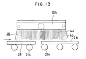
- Figs. 11 to 13 shows other preferred embodiments.
- N2 gas as a low reactive gas is applied from a conduit 38 to the interior of the furnace through a plurality of openings 40 defined in the front and rear of the reducing burner 10 so as to provide a N2 gas zone.
- a material 280 is wrapped by the reducing gas during a reducing operation.
- the N2 gas zone eliminates those gases in the previous and following operations. Accordingly, the surface of the material can be reduced under constant and stable conditions to provide a high quality product, that is, products of different colors and tones.
- openings 42 are formed in the side wall of the furnace to provide a N2 gas zone in the furnace.
- the other components are identical to those in the embodiment shown in Fig. 11 and will not be described in detail.
- a reducing flame 44 is supplied from a reducing burner 10A to reduce the surface of the material 28.
- a pair of N2 gas injection holes are defined in front and rear ends of the reducing burner 10A to provide a N2 gas zone 46 so as to eliminate an external atomosphere.
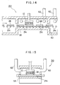
- Figs. 14 and 15 shows preferred embodiments of the present invention.
- the reducing burner 10 is oriented downwards in the reduction zone rearwardly of the firing zone of the continuous kiln 210 so as to apply a reducing flame directly to the surface of the material 28 during a reducing operation.
- 60 is an exhaust duct.
- a refractory body 58 is arranged immediately below the reducing burner 10 and extends in the longitudinal direction of the continuous kiln 210 so as to prevent the reducing flame from passing downwardly between the rollers 214.
- the material 28 is fired while the material 28 is conveyed from the inlet toward the outlet of the kiln 210 by the rollers 214, more specifically, when the material 28 passes through the firing zone. Reduction takes place by the burner 10 in the reduction zone downstream of the firing zone.
- the tile or material is then introduced into the cooling zone 62 and thereafter, discharged to an atomosphere for cooling purposes.
- the continuous kiln 210 includes the shielding body 58 below the rollers to prevent a reducing flame by the burner 10 from passing between the materials 28, 28 and the rollers 214.
- the flame in no way flares when the materials 28 pass immediately below the burner 10. Reducing conditions can also be maintained in the reduction zone. This allows the reducing flame to fully function so as to constantly reduce the materials 28 and thus, provide a reduced color as desired.
- a refractory plate as a refractory body may be mounted below the rollers 214.
- a tile may be placed on a plate during conveyance.
- the floor of the furnace may be used as a refractory body. Any other means can be used as a refractory body provided that a flame is prevented from passing downwardly between the rollers 214.
- the burner is mounted in the continuous kiln to apply a reducing flame directly to a material during a reducing operation. This results in reduction of the material under stable conditions so as to continuously provide products of equal color and constant quality on a mass production basis.
Landscapes
- Engineering & Computer Science (AREA)
- Mechanical Engineering (AREA)
- General Engineering & Computer Science (AREA)
- Tunnel Furnaces (AREA)
- Furnace Details (AREA)
- Gas Burners (AREA)
Applications Claiming Priority (2)
| Application Number | Priority Date | Filing Date | Title |
|---|---|---|---|
| JP52373/90 | 1990-03-02 | ||
| JP2052373A JPH03255807A (ja) | 1990-03-02 | 1990-03-02 | 焼成物の表面還元処理用バーナ |
Publications (2)
| Publication Number | Publication Date |
|---|---|
| EP0471087A1 true EP0471087A1 (de) | 1992-02-19 |
| EP0471087A4 EP0471087A4 (en) | 1992-08-12 |
Family
ID=12913005
Family Applications (1)
| Application Number | Title | Priority Date | Filing Date |
|---|---|---|---|
| EP19910904807 Withdrawn EP0471087A4 (en) | 1990-03-02 | 1991-02-28 | Continuous firing furnace |
Country Status (5)
| Country | Link |
|---|---|
| US (1) | US5248255A (de) |
| EP (1) | EP0471087A4 (de) |
| JP (1) | JPH03255807A (de) |
| KR (1) | KR960004797B1 (de) |
| WO (1) | WO1991013307A1 (de) |
Families Citing this family (23)
| Publication number | Priority date | Publication date | Assignee | Title |
|---|---|---|---|---|
| CN1098824C (zh) * | 1997-10-03 | 2003-01-15 | 康宁股份有限公司 | 陶瓷蜂窝体的烧制方法 |
| JP3783366B2 (ja) * | 1997-10-09 | 2006-06-07 | 松下電器産業株式会社 | 焼成炉 |
| JP2001524450A (ja) | 1997-12-02 | 2001-12-04 | コーニング インコーポレイテッド | セラミックハニカム体の焼成方法 |
| ATE321013T1 (de) * | 1997-12-02 | 2006-04-15 | Corning Inc | Verfahren zum brennen keramischer wabenkörper in einem tunnelofen |
| ATE465140T1 (de) * | 1997-12-02 | 2010-05-15 | Corning Inc | Verfahren zum brennen von keramischen honigwabenstrukturen |
| US6325963B1 (en) | 1997-12-22 | 2001-12-04 | Corning Incorporated | Method for firing ceramic honeycomb bodies |
| BR9813730A (pt) * | 1997-12-22 | 2000-10-10 | Corning Inc | Método para queima de corpos alveolares cerâmicos e um forno em túnel usado para o mesmo |
| IT248291Y1 (it) * | 1999-12-10 | 2002-12-16 | Sacmi Forni Spa | Forno monostrato per prodotti ceramici. |
| US6241515B1 (en) * | 2000-05-30 | 2001-06-05 | Tat Technologies, Inc | Device and method for treating combustibles obtained from a thermal processing apparatus and apparatus employed thereby |
| DE102011120681A1 (de) * | 2011-12-08 | 2013-06-13 | Linde Aktiengesellschaft | Anlage und Verfahren zum Vorwärmen von Platinen beim Warmumformen |
| US10281173B2 (en) * | 2012-06-28 | 2019-05-07 | Purpose Co., Ltd. | Burner, combustion apparatus, method for combustion, method for controlling combustion, recording medium, and water heater |
| US10571124B2 (en) | 2013-02-14 | 2020-02-25 | Clearsign Combustion Corporation | Selectable dilution low NOx burner |
| US10458649B2 (en) | 2013-02-14 | 2019-10-29 | Clearsign Combustion Corporation | Horizontally fired burner with a perforated flame holder |
| WO2014127306A1 (en) | 2013-02-14 | 2014-08-21 | Clearsign Combustion Corporation | SELECTABLE DILUTION LOW NOx BURNER |
| US10190767B2 (en) | 2013-03-27 | 2019-01-29 | Clearsign Combustion Corporation | Electrically controlled combustion fluid flow |
| WO2014183135A1 (en) | 2013-05-10 | 2014-11-13 | Clearsign Combustion Corporation | Combustion system and method for electrically assisted start-up |
| WO2015042613A1 (en) | 2013-09-23 | 2015-03-26 | Christopher A. Wiklof | POROUS FLAME HOLDER FOR LOW NOx COMBUSTION |
| US20150104748A1 (en) | 2013-10-14 | 2015-04-16 | Clearsign Combustion Corporation | Electrodynamic combustion control (ecc) technology for biomass and coal systems |
| CN106103338B (zh) | 2014-02-14 | 2018-04-20 | 克利尔赛恩燃烧公司 | 具有有孔火焰保持器的顶烧式燃烧器 |
| WO2016133934A1 (en) | 2015-02-17 | 2016-08-25 | Clearsign Combustion Corporation | Methods of upgrading a conventional combustion system to include a perforated flame holder |
| US10006715B2 (en) * | 2015-02-17 | 2018-06-26 | Clearsign Combustion Corporation | Tunnel burner including a perforated flame holder |
| US11027456B2 (en) * | 2015-11-05 | 2021-06-08 | Shildan, Inc. | Ceramic composite |
| CN108291717B (zh) | 2016-01-13 | 2020-12-11 | 美一蓝技术公司 | 瓷砖组之间具有间隙的穿孔火焰保持器 |
Family Cites Families (13)
| Publication number | Priority date | Publication date | Assignee | Title |
|---|---|---|---|---|
| US3100811A (en) * | 1960-05-31 | 1963-08-13 | Frederick S Bloom | Metal heating furnace |
| DE1529197B1 (de) * | 1966-04-06 | 1970-04-30 | Kurt Krieger | Strahlungsbrenner |
| US3540705A (en) * | 1969-02-10 | 1970-11-17 | Bloom Eng Co Inc | Exteriorly cooled furnace roller assembly |
| GB1533309A (en) * | 1976-12-06 | 1978-11-22 | Thermo Electron Corp | Method of heating flat strip stock and furnace therefor |
| US4504218A (en) * | 1981-02-03 | 1985-03-12 | Matsushita Electric Industrial Co., Ltd. | Ceramic burner plate |
| JPS5852980A (ja) * | 1981-09-26 | 1983-03-29 | 高砂工業株式会社 | 還元焼成炉 |
| JPS599489A (ja) * | 1982-07-08 | 1984-01-18 | 高砂工業株式会社 | トンネル炉の雰囲気制御装置 |
| JPS62279999A (ja) * | 1986-05-29 | 1987-12-04 | 凸版印刷株式会社 | 転写印刷方法 |
| US4936771A (en) * | 1987-08-26 | 1990-06-26 | Sidwell Clarence W | Skid mark erasure system |
| JPH01121682A (ja) * | 1987-11-05 | 1989-05-15 | Inax Corp | 連続焼成炉 |
| JPH0714353Y2 (ja) * | 1988-07-08 | 1995-04-05 | 中外炉工業株式会社 | ローラハース型熱処理炉 |
| US4838241A (en) * | 1988-08-05 | 1989-06-13 | Rieger Heinz H | Fireplace natural gas and propane burner assembly |
| BE1003054A3 (nl) * | 1989-03-29 | 1991-11-05 | Bekaert Sa Nv | Brandermembraan. |
-
1990
- 1990-03-02 JP JP2052373A patent/JPH03255807A/ja active Pending
-
1991
- 1991-02-28 KR KR1019910701500A patent/KR960004797B1/ko not_active Expired - Lifetime
- 1991-02-28 US US07/768,889 patent/US5248255A/en not_active Expired - Fee Related
- 1991-02-28 EP EP19910904807 patent/EP0471087A4/en not_active Withdrawn
- 1991-02-28 WO PCT/JP1991/000263 patent/WO1991013307A1/ja not_active Ceased
Also Published As
| Publication number | Publication date |
|---|---|
| US5248255A (en) | 1993-09-28 |
| JPH03255807A (ja) | 1991-11-14 |
| KR920701772A (ko) | 1992-08-12 |
| KR960004797B1 (ko) | 1996-04-13 |
| WO1991013307A1 (fr) | 1991-09-05 |
| EP0471087A4 (en) | 1992-08-12 |
Similar Documents
| Publication | Publication Date | Title |
|---|---|---|
| US5248255A (en) | Continuous kiln | |
| KR850000949B1 (ko) | 산소흡기기 버너의 용광로 발화공정 | |
| US4642047A (en) | Method and apparatus for flame generation and utilization of the combustion products for heating, melting and refining | |
| US4945841A (en) | Apparatus or method for carrying out combustion in a furnace | |
| US5346524A (en) | Oxygen/fuel firing of furnaces with massive, low velocity, turbulent flames | |
| KR100275395B1 (ko) | 유리 용융로에서 방출되는 질소 산화물의 양을 감소시키는 방법 | |
| EP0878681A2 (de) | Einrichtung und Verfahren zum Feuerungskontrolle | |
| US6461145B1 (en) | Flat flame burners | |
| US4329142A (en) | Method for heat treatment of clay and refractory ware | |
| JP2023510370A (ja) | 電気溶融炉に連続供給される金属装入物を予熱するための改良されたプロセス及びプラント | |
| JP2004077007A (ja) | 連続式加熱炉及びその操業方法 | |
| EP4150253B1 (de) | Brenner und verfahren zum brennen von keramikteilen | |
| RU2052726C1 (ru) | Устройство для дожигания сбросных газов | |
| EP0506043B1 (de) | Brenner zur Russerzeugung und Ofen mit einem derartigen Brenner zur Russablagerung | |
| JPH04270884A (ja) | ローラーハース連続炉 | |
| US3895906A (en) | Heating process and apparatus using oxygen | |
| US5639233A (en) | Kiln construction and method of firing the same | |
| JPH03255884A (ja) | 連続焼成炉 | |
| HU210661B (en) | Ignition set | |
| SU1514808A1 (ru) | Способ автодинамического управлени факелом регенеративного нагревательного колодца | |
| JPS6358201B2 (de) | ||
| JPS6257592B2 (de) | ||
| SU908872A1 (ru) | Способ зажигани агломерационной шихты | |
| JPH0551644B2 (de) | ||
| SU1039967A1 (ru) | Способ выплавки стали в двухванной печи |
Legal Events
| Date | Code | Title | Description |
|---|---|---|---|
| PUAI | Public reference made under article 153(3) epc to a published international application that has entered the european phase |
Free format text: ORIGINAL CODE: 0009012 |
|
| 17P | Request for examination filed |
Effective date: 19911030 |
|
| AK | Designated contracting states |
Kind code of ref document: A1 Designated state(s): AT BE CH DE DK ES FR GB GR IT LI LU NL SE |
|
| A4 | Supplementary search report drawn up and despatched |
Effective date: 19920626 |
|
| AK | Designated contracting states |
Kind code of ref document: A4 Designated state(s): AT BE CH DE DK ES FR GB GR IT LI LU NL SE |
|
| 17Q | First examination report despatched |
Effective date: 19930712 |
|
| STAA | Information on the status of an ep patent application or granted ep patent |
Free format text: STATUS: THE APPLICATION HAS BEEN WITHDRAWN |
|
| 18W | Application withdrawn |
Withdrawal date: 19931105 |