EP0470714B1 - Forming and arranging functional modules - Google Patents
Forming and arranging functional modules Download PDFInfo
- Publication number
- EP0470714B1 EP0470714B1 EP91306473A EP91306473A EP0470714B1 EP 0470714 B1 EP0470714 B1 EP 0470714B1 EP 91306473 A EP91306473 A EP 91306473A EP 91306473 A EP91306473 A EP 91306473A EP 0470714 B1 EP0470714 B1 EP 0470714B1
- Authority
- EP
- European Patent Office
- Prior art keywords
- modules
- frame
- module
- engine room
- equipment
- Prior art date
- Legal status (The legal status is an assumption and is not a legal conclusion. Google has not performed a legal analysis and makes no representation as to the accuracy of the status listed.)
- Revoked
Links
- 238000000034 method Methods 0.000 claims description 26
- 238000009434 installation Methods 0.000 description 10
- 239000012530 fluid Substances 0.000 description 9
- 238000007689 inspection Methods 0.000 description 8
- 238000012423 maintenance Methods 0.000 description 8
- 238000001816 cooling Methods 0.000 description 6
- 230000001050 lubricating effect Effects 0.000 description 5
- 238000004519 manufacturing process Methods 0.000 description 5
- 239000013505 freshwater Substances 0.000 description 3
- 230000000694 effects Effects 0.000 description 2
- 239000000314 lubricant Substances 0.000 description 2
- 239000003921 oil Substances 0.000 description 2
- 230000002787 reinforcement Effects 0.000 description 2
- 239000013535 sea water Substances 0.000 description 2
- 238000009423 ventilation Methods 0.000 description 2
- 230000008859 change Effects 0.000 description 1
- 239000010727 cylinder oil Substances 0.000 description 1
- 230000006872 improvement Effects 0.000 description 1
- 230000008569 process Effects 0.000 description 1
Images




Classifications
-
- B—PERFORMING OPERATIONS; TRANSPORTING
- B63—SHIPS OR OTHER WATERBORNE VESSELS; RELATED EQUIPMENT
- B63B—SHIPS OR OTHER WATERBORNE VESSELS; EQUIPMENT FOR SHIPPING
- B63B11/00—Interior subdivision of hulls
- B63B11/02—Arrangement of bulkheads, e.g. defining cargo spaces
-
- B—PERFORMING OPERATIONS; TRANSPORTING
- B63—SHIPS OR OTHER WATERBORNE VESSELS; RELATED EQUIPMENT
- B63B—SHIPS OR OTHER WATERBORNE VESSELS; EQUIPMENT FOR SHIPPING
- B63B3/00—Hulls characterised by their structure or component parts
- B63B3/02—Hulls assembled from prefabricated sub-units
- B63B3/04—Hulls assembled from prefabricated sub-units with permanently-connected sub-units
- B63B3/06—Hulls assembled from prefabricated sub-units with permanently-connected sub-units the sub-units being substantially identical
Definitions
- the present invention relates to a method for forming functional modules and a method of arranging such modules.
- Figure 9 is a schematic view of a conventionally fitted out ship's engine room a in which various types of machine or apparatus c are brought into the room a and are arranged on a hull structure b in the room a.
- Reference character d represents a piping arrangement; and e, a ventilation arrangement or an electric cable arrangement.
- the machines or installations c are not necessarily installed in accordance with their particular functions and are arranged in scattered or random manner in the engine room a. As the result, when the components of a main engine lubricating and cooling system are to be operated or maintained or inspected, an operator or inspector must walk about in the engine room a, resulting in inefficient operation or maintenance and inspection.
- the installations c are arranged two-dimensionally over a relatively extensive area on the hull structure b of the engine room a, resulting in ineffective utilization of the space in the room a.
- the Naval Engineers Journal vol. 83, No. 5, Oct. 71, pp 45-52 discusses the possibility of the production of modular warships.
- the article contemplates a ship having large scale modules dedicated to a particular function, e.g. a weapons module might comprise a missile launcher, magazine, handling equipment and fire control electronics.
- a module could be inserted in a space in a ship's structure and modules could be interchangeable.
- US3363597 discloses a method of constructing a ship comprising assembling a hull envelope having compartments and inserting a framework 51 which defines a number of cuboid spaces arranged in 3 dimensions, into each compartment. Self-contained modules are then lowered into each space in the framework.
- An object of the present invention is to facilitate the operation and maintenance and inspection of various kinds of equipment, such as outfits, and to enable outfitting to be performed independently of the hull structure, thereby facilitating designing of an engine room or a plant and outfitting and operation of installations or plant elements as well as effectively utilizing the available space.
- a method of mounting engine room equipment in the engine room of a ship comprises dividing the equipment into a plurality of groups, the equipment of each group having related functions, mounting each group of equipment with related functions in a respective frame, each frame defining a frame module, and arranging said frame modules in abutting horizontally side-by-side and vertically stacked relationships in said engine room.
- the present invention also embraces a method of arranging modules which comprises subdividing a hull structure module into separately fabricated deck modules and block modules for seating on said deck modules with at least some of said block modules being horizontally spaced from each other, accommodating outfits having related functions in separate frames, each defining a frame module and being of a size placeable on a deck module in a block module or between block modules or in place of a block module, and replaceably placing said frame modules on said deck modules, in or between block modules or in place of said block modules.
- engine room equipment can be modularised.
- One or more such modules are arranged in an engine room space side by side and one above the other in a replaceable manner thereby facilitating maintenance and inspection of the equipment, facilitating design of the engine room and facilitating fitting out and operation of the equipment and ensuring that the space is effectively utilised.
- Figures 1 and 2 relate to an embodiment of the method for forming modules according to the present invention as claimed in claims 1,2 and 3.
- a “module” as described below is defined as a standard unit for facilitating operation, maintenance and inspection, designing and outfitting and for minimising dead space.
- Figure 1 is a flow chart showing the procedure for dividing the installations or units into modules according to their function, the Roman numerals indicating the conventional classification according to the fluid system.
- I represents a first fluid system (e.g. cooling fresh water system); II, a second fluid system (e.g. lubricant system); and III, a third fluid system (.e.g. cooling seawater system).
- first fluid system e.g. cooling fresh water system
- second fluid system e.g. lubricant system
- III a third fluid system
- Each fluid system I,II,III contains various types of equipment, such as outfits or plant elements, with different functions (uses and equipments).
- the equipment or units in each of the fluid systems I,II,III etc are divided or classified according to their functions A,B,C, etc.
- equipment having common functions are grouped from the fluid systems I,II,III etc into A function module 1 (e.g. main engine lubricating and cooling module), B function module 2 (e.g. stern tube lubricating module), C function module 3 (.e.g. steam generation module) etc.
- a function module 1 e.g. main engine lubricating and cooling module
- B function module 2 e.g. stern tube lubricating module
- C function module 3 e.g. steam generation module
- the equipment is divided into A,B,C etc function modules 1,2,3, etc and the equipment with related functions is accommodated in a standard frame with a predetermined size, say, about the size of 20 ft/40 ft container and a frame module is made up. If the units can be accommodated in a standard frame only by dividing them into A,B,C,...function modules 1,2,3,... there is no need to subdivide these function modules, but in the case of a ship, they can scarcely be accommodated into the standard frames even when they are divided into main engine lubricating and cooling module, stern tube lubricating module and steam generation module.
- each of the function modules 1,2,3, etc may be further subdivided by function.
- a function module may be subdivided into A1 function module (e.g. cooling fresh water system) 1-1, A2 function module (e.g. cylinder oil system) 1-2, and so on.
- B function module 2 may be subdivided into B1 function module 2-1, B2 function module 2-2, and so on and C function module 3, into C1 function module 3-1, C2 function module 3-2, etc.
- the A1, A2,...function modules 1-1, 1-2,...the B1, B2,...function modules 2-1, 2-2,...and the C1, C2,...function modules 3-1, 3-2,... may be further subdivided.
- the A1 function module 1-1 may be subdivided into A1-1 function module (e.g., tank module) 1-1-1, A1-2 function module (e.g. pump module) 1-1-2; the A2 function module 1-2, into A2-1 function module 1-2-1 and A2-2 function module 1-2-2 and so on.
- each function module as described above are accommodated in the standard frame of, for example, 20 ft/40 ft.
- the combination of the modules varies according to the volumes of the A1-1 function module 1-1-1, the A1-2 function module 1-1-2, the A2-1 function module 1-2-1, the A2-2 function module 1-2-2 etc.
- the A1-1 and A1-2 function modules 1-1-1 and 1-1-2 may be accommodated as a module into a frame to form a frame module
- the A2-2 function module 1-2-2 may be accommodated in a frame by itself to form a frame module.
- Figure 2 shows a frame module 13 in which the units 12, classified according to their functions by the procedure of Figure 1, are accommodated in a standard frame 11, such as a container.
- a frame module may be lifted as a unit and a plurality of frame modules 13 are prepared and are accommodated three-dimensionally in a space.
- Figure 3 shows a first embodiment of the method of arrangement of modules in accordance with the present invention as claimed in claims 4 to 6 and 8.
- the frame modules 13 of Figure 2 are three-dimensionally arranged in a space 14, such as an engine room as shown in the perspective view.
- the three-dimensional arrangement of the frame modules 13 is determined by giving full consideration to operational requirements and convenience in maintenance and inspection of the equipment.
- the various devices and units are divided according to their functions (uses and equipments) and the divided devices and units are accommodated in frames as modules to form frame modules.
- the frame modules thus made up are three-dimensionally arranged in a predetermined space, having particular regard to function. This will enhance operation of the equipment, facilitate maintenance and inspection and result in effective utilisation of the space. When the performance or functional characteristics of the equipment are to be changed, this is accomplished by replacing the frame modules 13.
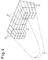
- Figures 4 and 5 show a second embodiment 2 of the method of arranging modules in accordance with the present invention as claimed in claims 4,5 and 8.
- reference numeral 21 represents the engine room of a ship 22; 23, a space aft of a transverse bulkhead 24 in the front portion of the engine room 21; and 25, spaces inside shell plates 26 near the bulkhead 24.
- the frame modules are arranged three-dimensionally in the spaces 23 and 25 and are formed similarly to the frame modules of Figure 3 in the first embodiment. More specifically, the outfits having the same functions (uses and equipments) are accommodated in a frame so that frame modules 27 as shown in Figure 4 are formed.
- Such frame modules 27 are arranged three-dimensionally in the spaces 23 and 25 in the engine room 21 of Figure 5.
- the three-dimensional arrangement of the frame modules 27 is as shown in Figure 4.
- the available spaces 23 and 25 are behind transverse bulkhead 24 and part of the internal spaces inside the shell plates 26, as shown in Figure 5, while in the case of a large ship, spaces 28 behind the spaces 25 can be utilised for the three-dimensional arrangement of the frame modules, as shown in Figure 5.
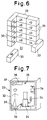
- the outfits or devices 34 necessary for the engine room 31 are grouped according to their functions (uses and equipments) and are accommodated in frames 32, such as containers, and are utilised into frame modules 33.
- the frame module or modules 33 are then arranged as a single unit or as two or more units at required point or points in the engine room 31 to complete the outfitting thereof.
- outfits 34 with related functions (uses and equipments) necessary for the engine room 31 are accommodated in the frame 32, such as a 20 ft/40 ft general-purpose container.
- Lifting means 35, passage means 36, ventilation means 37, lighting means 38, piping means 39, etc. are also accommodated in the frame 32, thus providing the frame module 33 with the grouped outfits 34.
- the frame modules 33 for the grouped outfits 34 are arranged in predetermined outfit sections 40 to 49, thus completing the outfitting of the engine room 31.
- reference numeral 40 represents a propulsion section; 41, a bilge processing section; 42, an oil tank section; 43, an oil processing section; 44, a lubricant section; 45, a steam generation section; 46, a fresh water section; 47, an option space; 48, a seawater section; and 49, an elevator section.
- the outfits 34 related to each of the outfit sections 40 to 49 are accommodated in the respective frames 32.
- the outfitting of the engine room 31 is completed by the use of the frame modules 33 with the outfits 34 of related functions necessary for the engine room 31 being accommodated in the frames 32, such as containers.
- This will eliminate the work of installing the outfits on the hull structure using reinforcement members as in the prior art and eliminate the necessity of adjusting the details of the design and outfitting schedule thus facilitating the handling of the outfits. Since the fitting out can be performed independently of the hull structure by the use of the above frame modules 33, it may be performed in a place other than a module factory or a shore-based fitting out station of a shipyard.
- the design of the fitting out may be effected using the frame 32 as origin coordinates, thereby enhacing the applicability to other ships. This contributes to the improvement of basic, functional and production design as well as the fitting out process.
- reference numeral 51 represents a hull structure module which comprises hull deck modules 52 and hull structure block modules (skeleton structure modules) 53.
- Outfits 56 having related functions are accommodated in the frames 54 which are sized to be placeable between or in place of the hull structure block modules 53, thus forming the frame modules 55.
- the frame modules 55 are placed replaceably between or in place of the hull structure block modules 53, as shown by the arrow 57 or 58.
- the hull structure module 51 is thus subdivided into hull deck modules 52 and hull structure block modules 53 which are fabricated separately.
- the replaceability of the hull structure block modules 53 will expand the engineering range and enhance the applicability to other ships. Subdivision of the hull structure module 51 in fabrication will shorten the time required for fabrication of the modules 51.
- Outfits 56 having related functions are accommodated in a frame 54 with a predetermined volume to make up a frame module 55 which is then placed replaceably between or in place of the hull structure block modules 53.
- the replaceable arrangement of the frame modules 55 will widen the engineering range and increase the applicability to other ships.
- the method for forming modules in accordance with the present invention as claimed in claim 1 has the advantageous effects of improving handling of equipment, such as outfits, and facilitating maintenance and inspection.
Landscapes
- Chemical & Material Sciences (AREA)
- Engineering & Computer Science (AREA)
- Combustion & Propulsion (AREA)
- Mechanical Engineering (AREA)
- Ocean & Marine Engineering (AREA)
- Automatic Assembly (AREA)
- General Factory Administration (AREA)
- Structures Of Non-Positive Displacement Pumps (AREA)
- Cultivation Of Plants (AREA)
Description
- The present invention relates to a method for forming functional modules and a method of arranging such modules.
- Figure 9 is a schematic view of a conventionally fitted out ship's engine room a in which various types of machine or apparatus c are brought into the room a and are arranged on a hull structure b in the room a. Reference character d represents a piping arrangement; and e, a ventilation arrangement or an electric cable arrangement.
- The machines or installations c are not necessarily installed in accordance with their particular functions and are arranged in scattered or random manner in the engine room a. As the result, when the components of a main engine lubricating and cooling system are to be operated or maintained or inspected, an operator or inspector must walk about in the engine room a, resulting in inefficient operation or maintenance and inspection.
- Moreover, the installations c are arranged two-dimensionally over a relatively extensive area on the hull structure b of the engine room a, resulting in ineffective utilization of the space in the room a.
- The conventional outfitting procedure, in which each of the machines or devices c is installed on the hull structure b, will cause various additional problems. Adjustment of detailed schedules for the design and outfitting steps are needed for the hull structure b and machines or installations c. Reinforcement members are required to furnish the installations c on the hull structure b. Designing must be effected with full consideration of the hull structure. Re-designing of the installations c is required if there is any change in the hull since the layout of the installations c depends upon the hull structure.
- The Naval Engineers Journal vol. 83, No. 5, Oct. 71, pp 45-52 discusses the possibility of the production of modular warships. The article contemplates a ship having large scale modules dedicated to a particular function, e.g. a weapons module might comprise a missile launcher, magazine, handling equipment and fire control electronics. A module could be inserted in a space in a ship's structure and modules could be interchangeable.
- US3363597 discloses a method of constructing a ship comprising assembling a hull envelope having compartments and inserting a
framework 51 which defines a number of cuboid spaces arranged in 3 dimensions, into each compartment. Self-contained modules are then lowered into each space in the framework. - An object of the present invention is to facilitate the operation and maintenance and inspection of various kinds of equipment, such as outfits, and to enable outfitting to be performed independently of the hull structure, thereby facilitating designing of an engine room or a plant and outfitting and operation of installations or plant elements as well as effectively utilizing the available space.
- According to the present invention a method of mounting engine room equipment in the engine room of a ship comprises dividing the equipment into a plurality of groups, the equipment of each group having related functions, mounting each group of equipment with related functions in a respective frame, each frame defining a frame module, and arranging said frame modules in abutting horizontally side-by-side and vertically stacked relationships in said engine room.
- The present invention also embraces a method of arranging modules which comprises subdividing a hull structure module into separately fabricated deck modules and block modules for seating on said deck modules with at least some of said block modules being horizontally spaced from each other, accommodating outfits having related functions in separate frames, each defining a frame module and being of a size placeable on a deck module in a block module or between block modules or in place of a block module, and replaceably placing said frame modules on said deck modules, in or between block modules or in place of said block modules.
- Thus in the present invention engine room equipment can be modularised. One or more such modules are arranged in an engine room space side by side and one above the other in a replaceable manner thereby facilitating maintenance and inspection of the equipment, facilitating design of the engine room and facilitating fitting out and operation of the equipment and ensuring that the space is effectively utilised.
- Further features and details of the invention will be apparent from the following description of certain preferred embodiments which is given by way of example with reference to Figures 1 to 8 of the accompanying drawings, in which:-
- Figure 1 shows an embodiment of a method of forming modules in accordance with the present invention and is a flow chart showing a procedure for dividing the installations or devices according to their functions which have been classified in accordance with their fluid system;
- Figure 2 is a perspective view of a frame module which is provided by accommodating into a frame the installations or devices, which have been divided according to their functions by the procedure shown in Figure 1;
- Figure 3 shows a first embodiment of the method of arranging the modules in accordance with the present invention and is a perspective view showing the three-dimensional arrangement of frame modules as shown in Figure 2;
- Figure 4 is a perspective view of a second embodiment of the method of arranging the modules in accordance with the present invention and shows the three-dimensional arrangement of the frame modules in an engine room of a ship.
- Figure 5 is a perspective view showing spaces in an engine room of a ship shown in Figure 4;
- Figure 6 is a perspective view of a third embodiment of the method of arranging modules in accordance with the present invention;
- Figure 7 shows an example of a frame module used in the method of arranging modules shown in Figure 6; and
- Figure 8 is a perspective view of a fourth embodiment of the method of arranging modules in accordance with the present invention.
- Figures 1 and 2 relate to an embodiment of the method for forming modules according to the present invention as claimed in
claims - A "module" as described below is defined as a standard unit for facilitating operation, maintenance and inspection, designing and outfitting and for minimising dead space.
- Figure 1 is a flow chart showing the procedure for dividing the installations or units into modules according to their function, the Roman numerals indicating the conventional classification according to the fluid system. I represents a first fluid system (e.g. cooling fresh water system); II, a second fluid system (e.g. lubricant system); and III, a third fluid system (.e.g. cooling seawater system). There are many other fluid systems but these are not shown in the figure.
- Each fluid system I,II,III contains various types of equipment, such as outfits or plant elements, with different functions (uses and equipments). The equipment or units in each of the fluid systems I,II,III etc are divided or classified according to their functions A,B,C, etc. Thus, equipment having common functions are grouped from the fluid systems I,II,III etc into A function module 1 (e.g. main engine lubricating and cooling module), B function module 2 (e.g. stern tube lubricating module),
C function module 3 (.e.g. steam generation module) etc. - The equipment is divided into A,B,C
etc function modules ...function modules - For this reason, each of the
function modules B function module 2 may be subdivided into B₁ function module 2-1, B₂ function module 2-2, and so on andC function module 3, into C₁ function module 3-1, C₂ function module 3-2, etc. - If necessary, the A₁, A₂,...function modules 1-1, 1-2,...the B₁, B₂,...function modules 2-1, 2-2,...and the C₁, C₂,...function modules 3-1, 3-2,...may be further subdivided. For example, the A₁ function module 1-1 may be subdivided into A₁-1 function module (e.g., tank module) 1-1-1, A₁-2 function module (e.g. pump module) 1-1-2; the A₂ function module 1-2, into A₂-1 function module 1-2-1 and A₂-2 function module 1-2-2 and so on.
- The equipment of each function module as described above are accommodated in the standard frame of, for example, 20 ft/40 ft. The combination of the modules varies according to the volumes of the A₁-1 function module 1-1-1, the A₁-2 function module 1-1-2, the A₂-1 function module 1-2-1, the A₂-2 function module 1-2-2 etc. For example, as shown by the chain dotted line X in Figure 1, the A₁-1 and A₁-2 function modules 1-1-1 and 1-1-2 may be accommodated as a module into a frame to form a frame module, and as shown by the chain dotted line Y in Figure 1, the A₂-2 function module 1-2-2 may be accommodated in a frame by itself to form a frame module.
- Figure 2 shows a
frame module 13 in which theunits 12, classified according to their functions by the procedure of Figure 1, are accommodated in astandard frame 11, such as a container. Such a frame module may be lifted as a unit and a plurality offrame modules 13 are prepared and are accommodated three-dimensionally in a space. - Figure 3 shows a first embodiment of the method of arrangement of modules in accordance with the present invention as claimed in claims 4 to 6 and 8. In this embodiment, the
frame modules 13 of Figure 2 are three-dimensionally arranged in aspace 14, such as an engine room as shown in the perspective view. The three-dimensional arrangement of theframe modules 13 is determined by giving full consideration to operational requirements and convenience in maintenance and inspection of the equipment. - As described above, in the embodiment of the present invention, the various devices and units are divided according to their functions (uses and equipments) and the divided devices and units are accommodated in frames as modules to form frame modules. The frame modules thus made up are three-dimensionally arranged in a predetermined space, having particular regard to function. This will enhance operation of the equipment, facilitate maintenance and inspection and result in effective utilisation of the space. When the performance or functional characteristics of the equipment are to be changed, this is accomplished by replacing the
frame modules 13. - Figures 4 and 5 show a
second embodiment 2 of the method of arranging modules in accordance with the present invention as claimed in claims 4,5 and 8. - In Figure 5,
reference numeral 21 represents the engine room of aship 22; 23, a space aft of atransverse bulkhead 24 in the front portion of theengine room 21; and 25, spaces insideshell plates 26 near thebulkhead 24. - The frame modules are arranged three-dimensionally in the
spaces frame modules 27 as shown in Figure 4 are formed. -
Such frame modules 27 are arranged three-dimensionally in thespaces engine room 21 of Figure 5. The three-dimensional arrangement of theframe modules 27 is as shown in Figure 4. By three-dimensionally arranging theframe modules 27 in the vertical and horizontal directions, the outfits can be freely arranged regardless of the hull structure and thespaces engine room 21 can be effectively utilised. - In the case of a small ship, the
available spaces transverse bulkhead 24 and part of the internal spaces inside theshell plates 26, as shown in Figure 5, while in the case of a large ship,spaces 28 behind thespaces 25 can be utilised for the three-dimensional arrangement of the frame modules, as shown in Figure 5. - As shown in Figures 6 and 7, the outfits or
devices 34 necessary for theengine room 31 are grouped according to their functions (uses and equipments) and are accommodated inframes 32, such as containers, and are utilised intoframe modules 33. The frame module ormodules 33 are then arranged as a single unit or as two or more units at required point or points in theengine room 31 to complete the outfitting thereof. - More specifically, some
outfits 34 with related functions (uses and equipments) necessary for theengine room 31 are accommodated in theframe 32, such as a 20 ft/40 ft general-purpose container. Lifting means 35, passage means 36, ventilation means 37, lighting means 38, piping means 39, etc. are also accommodated in theframe 32, thus providing theframe module 33 with the groupedoutfits 34. Theframe modules 33 for the groupedoutfits 34 are arranged inpredetermined outfit sections 40 to 49, thus completing the outfitting of theengine room 31. In Figure 6,reference numeral 40 represents a propulsion section; 41, a bilge processing section; 42, an oil tank section; 43, an oil processing section; 44, a lubricant section; 45, a steam generation section; 46, a fresh water section; 47, an option space; 48, a seawater section; and 49, an elevator section. In theframe modules 33, therefore, theoutfits 34 related to each of theoutfit sections 40 to 49 are accommodated in the respective frames 32. - As described above, the outfitting of the
engine room 31 is completed by the use of theframe modules 33 with theoutfits 34 of related functions necessary for theengine room 31 being accommodated in theframes 32, such as containers. This will eliminate the work of installing the outfits on the hull structure using reinforcement members as in the prior art and eliminate the necessity of adjusting the details of the design and outfitting schedule thus facilitating the handling of the outfits. Since the fitting out can be performed independently of the hull structure by the use of theabove frame modules 33, it may be performed in a place other than a module factory or a shore-based fitting out station of a shipyard. Owing to modularisation of therelated outfits 34, the design of the fitting out may be effected using theframe 32 as origin coordinates, thereby enhacing the applicability to other ships. This contributes to the improvement of basic, functional and production design as well as the fitting out process. - In Figure 8,
reference numeral 51 represents a hull structure module which compriseshull deck modules 52 and hull structure block modules (skeleton structure modules) 53. -
Outfits 56 having related functions (uses and equipments) are accommodated in theframes 54 which are sized to be placeable between or in place of the hullstructure block modules 53, thus forming theframe modules 55. Theframe modules 55 are placed replaceably between or in place of the hullstructure block modules 53, as shown by thearrow - The
hull structure module 51 is thus subdivided intohull deck modules 52 and hullstructure block modules 53 which are fabricated separately. The replaceability of the hullstructure block modules 53 will expand the engineering range and enhance the applicability to other ships. Subdivision of thehull structure module 51 in fabrication will shorten the time required for fabrication of themodules 51.Outfits 56 having related functions are accommodated in aframe 54 with a predetermined volume to make up aframe module 55 which is then placed replaceably between or in place of the hullstructure block modules 53. The replaceable arrangement of theframe modules 55 will widen the engineering range and increase the applicability to other ships. - This facilitates designing of a ship's engine room and fitting out.
- As described above, the method for forming modules in accordance with the present invention as claimed in claim 1 has the advantageous effects of improving handling of equipment, such as outfits, and facilitating maintenance and inspection.
- The method of arranging modules in accordance with the present invention as claimed in
claim 2 has the advantageous effects of - I. improving handling of the outfits and facilitating maintenance and inspection; and
- II. being capable of freely fitting the outfits regardless of the hull structure.
- III. In the case where the method is used for fitting out a ship, it has the advantages that
- (i) the fitting out can be performed independently of the hull structure;
- (ii) the design can be effected with the frame being used as the origin coordinate and the applicability of the outfits to other ships can be increased;
- (iii) that handling is facilitated and fitting out can be performed at a place other than a module factory or a shore-based fitting out station in a shipyard;
- (iv) the designing, fitting out method and operational efficiency in the engine room are improved and the production engineering is facilitated; and
- (v) effective utilitisation of space
Claims (2)
- A method of mounting engine room equipment (12) in the engine room of a ship comprising dividing the equipment into a plurality of groups, the equipment (12) of each group having related functions, mounting each group of equipment with related functions in a respective frame (11), each frame (11) defining a frame module (13), and arranging said frame modules (13) in abutting horizontally side-by-side and vertically stacked relationships in said engine room (14; 21).
- A method of arranging of modules which comprises subdividing a hull structure module (51) into separately fabricated deck modules (52) and block modules (53) for seating on said deck modules (52) with at least some of said block modules (53) being horizontally spaced from each other, accommodating outfits (56) having related functions in separate frames (54), each defining a frame module (55) and being of a size placeable on a deck module (52) in a block module (53) or between block modules (53) or in place of a block module (53), and replaceably placing said frame modules (55) on said deck modules (52), in or between block modules or in place of said block modules (53).
Applications Claiming Priority (6)
| Application Number | Priority Date | Filing Date | Title |
|---|---|---|---|
| JP2206906A JPH0490984A (en) | 1990-08-06 | 1990-08-06 | How to install a ship engine room model |
| JP206906/90 | 1990-08-06 | ||
| JP28967790A JPH04163294A (en) | 1990-10-26 | 1990-10-26 | Method for forming a frame module and method for arranging a frame module formed by the method |
| JP289676/90 | 1990-10-26 | ||
| JP289677/90 | 1990-10-26 | ||
| JP28967690A JPH04163293A (en) | 1990-10-26 | 1990-10-26 | Outfitting method for engine room |
Publications (2)
| Publication Number | Publication Date |
|---|---|
| EP0470714A1 EP0470714A1 (en) | 1992-02-12 |
| EP0470714B1 true EP0470714B1 (en) | 1995-10-18 |
Family
ID=27328699
Family Applications (1)
| Application Number | Title | Priority Date | Filing Date |
|---|---|---|---|
| EP91306473A Revoked EP0470714B1 (en) | 1990-08-06 | 1991-07-15 | Forming and arranging functional modules |
Country Status (5)
| Country | Link |
|---|---|
| EP (1) | EP0470714B1 (en) |
| KR (1) | KR920004235A (en) |
| CN (1) | CN1039685C (en) |
| BR (1) | BR9103038A (en) |
| DE (1) | DE69113918T2 (en) |
Families Citing this family (4)
| Publication number | Priority date | Publication date | Assignee | Title |
|---|---|---|---|---|
| FI84999C (en) * | 1986-02-11 | 1992-02-25 | Masa Yards Oy | Ship Construction |
| DE4139542C2 (en) * | 1991-11-30 | 1999-12-30 | Thyssen Nordseewerke Gmbh | Ship, especially merchant ship |
| DE19532107C2 (en) * | 1995-08-31 | 1997-10-16 | Thyssen Nordseewerke Gmbh | Ship with horizontally extending flat surface elements arranged in the hull |
| KR101652493B1 (en) * | 2014-09-04 | 2016-08-30 | 삼성중공업 주식회사 | Prefabricated modular ship |
Family Cites Families (8)
| Publication number | Priority date | Publication date | Assignee | Title |
|---|---|---|---|---|
| DE1912802U (en) * | 1965-01-20 | 1965-03-25 | Plastische Planung Dr A Derich | DEVICE FOR PREPARING DESIGN TEMPLATES, IN PARTICULAR FOR PIPING IN SHIP BUILDING. |
| US3363597A (en) * | 1966-07-27 | 1968-01-16 | Gen Dynamics Corp | Ship and method of construction |
| US3400832A (en) * | 1966-08-15 | 1968-09-10 | Goetaverken Ab | Workshop |
| US4476798A (en) * | 1982-08-17 | 1984-10-16 | Consolidated Olympic Corporation | Integrated multiple purpose universal ship hull and replacement module system |
| FR2547411B2 (en) * | 1982-12-10 | 1987-01-16 | Sappel Sa | TURBINE FOR MULTI-JET LIQUID FLOW METER |
| JPS63130493A (en) * | 1986-11-18 | 1988-06-02 | Mitsubishi Heavy Ind Ltd | Equipping method for ship |
| JPH01186493A (en) * | 1988-01-19 | 1989-07-25 | Mitsubishi Heavy Ind Ltd | Outfitting article supporting structure for vessel engine room |
| JPH02310189A (en) * | 1989-05-25 | 1990-12-25 | Mitsubishi Heavy Ind Ltd | Construction method for inside structure section of ship engine room |
-
1991
- 1991-07-15 EP EP91306473A patent/EP0470714B1/en not_active Revoked
- 1991-07-15 DE DE69113918T patent/DE69113918T2/en not_active Revoked
- 1991-07-16 CN CN91104930A patent/CN1039685C/en not_active Expired - Lifetime
- 1991-07-16 KR KR1019910012147A patent/KR920004235A/en not_active Ceased
- 1991-07-16 BR BR919103038A patent/BR9103038A/en not_active IP Right Cessation
Also Published As
| Publication number | Publication date |
|---|---|
| KR920004235A (en) | 1992-03-27 |
| DE69113918D1 (en) | 1995-11-23 |
| CN1060268A (en) | 1992-04-15 |
| EP0470714A1 (en) | 1992-02-12 |
| BR9103038A (en) | 1992-04-28 |
| CN1039685C (en) | 1998-09-09 |
| DE69113918T2 (en) | 1996-04-04 |
Similar Documents
| Publication | Publication Date | Title |
|---|---|---|
| EP0470714A1 (en) | Forming and arranging functional modules | |
| Duchateau et al. | Early stage routing of distributed ship service systems for vulnerability reduction | |
| US5259332A (en) | Method for forming modules and method for arrangement thereof | |
| Jolliff | Modular ship design concepts | |
| EP0992424A2 (en) | Power converter arrangement for integration into a ship structure | |
| KR20020042767A (en) | Merchant navy vessel comprising a hull that is provided for accommodating goods and/or people | |
| Baade et al. | Modular outfitting | |
| EP1160155A2 (en) | Distributed machinery structure for ships | |
| Gunawan et al. | Optimization of module arrangement in ship engine room | |
| CA2084125A1 (en) | Ship, in particular merchant ship | |
| EP4337521B1 (en) | A modular ship system for configuration of a ship to carry out different tasks | |
| Chalfant | ESRDC notional ship data | |
| SE434720B (en) | PROCEDURE FOR ASSEMBLY OF THE SHOWER VESSEL WITH A MAIN POWER PLANT OF A VESSEL | |
| Stevens | Naval ship preliminary arrangements for operability and reduced vulnerability | |
| KEHOE JR, USN (RET) et al. | The Impact of Design Practices on Ship Size and Cost | |
| Strickland | Design Considerations for Unmanned Surface Vessels in Naval Service | |
| RU2223887C1 (en) | Underwater vehicle | |
| Kolich et al. | Lean IHOP transformation of shipyard erection block construction | |
| Aehia | X~ CJS1E | |
| KR100205777B1 (en) | One-deck engine room structure and arrangement method of medium and large ships | |
| Chryssostomidis et al. | Architectural Model to Enable Power System Tradeoff Studies | |
| KR20180063653A (en) | Ventilation System for Floating Offshore Structure | |
| Bethke et al. | Overhaul Work Booklet: USS Rathburne (FF-1057) | |
| Kinney | A disciplined approach to machinery arrangements in ship design | |
| JPH04163293A (en) | Outfitting method for engine room |
Legal Events
| Date | Code | Title | Description |
|---|---|---|---|
| PUAI | Public reference made under article 153(3) epc to a published international application that has entered the european phase |
Free format text: ORIGINAL CODE: 0009012 |
|
| AK | Designated contracting states |
Kind code of ref document: A1 Designated state(s): DE FR GB NL |
|
| 17P | Request for examination filed |
Effective date: 19920812 |
|
| 17Q | First examination report despatched |
Effective date: 19931025 |
|
| GRAA | (expected) grant |
Free format text: ORIGINAL CODE: 0009210 |
|
| AK | Designated contracting states |
Kind code of ref document: B1 Designated state(s): DE FR GB NL |
|
| REF | Corresponds to: |
Ref document number: 69113918 Country of ref document: DE Date of ref document: 19951123 |
|
| ET | Fr: translation filed | ||
| PLBQ | Unpublished change to opponent data |
Free format text: ORIGINAL CODE: EPIDOS OPPO |
|
| PLBI | Opposition filed |
Free format text: ORIGINAL CODE: 0009260 |
|
| PLBF | Reply of patent proprietor to notice(s) of opposition |
Free format text: ORIGINAL CODE: EPIDOS OBSO |
|
| 26 | Opposition filed |
Opponent name: BLOHM + VOSS INTERNATIONAL GMBH Effective date: 19960716 |
|
| NLR1 | Nl: opposition has been filed with the epo |
Opponent name: VOSS INTERNATIONAL GMBH |
|
| PLBF | Reply of patent proprietor to notice(s) of opposition |
Free format text: ORIGINAL CODE: EPIDOS OBSO |
|
| PLBF | Reply of patent proprietor to notice(s) of opposition |
Free format text: ORIGINAL CODE: EPIDOS OBSO |
|
| PLBF | Reply of patent proprietor to notice(s) of opposition |
Free format text: ORIGINAL CODE: EPIDOS OBSO |
|
| PGFP | Annual fee paid to national office [announced via postgrant information from national office to epo] |
Ref country code: FR Payment date: 19990625 Year of fee payment: 9 Ref country code: DE Payment date: 19990625 Year of fee payment: 9 |
|
| RDAH | Patent revoked |
Free format text: ORIGINAL CODE: EPIDOS REVO |
|
| PGFP | Annual fee paid to national office [announced via postgrant information from national office to epo] |
Ref country code: GB Payment date: 19990714 Year of fee payment: 9 |
|
| PGFP | Annual fee paid to national office [announced via postgrant information from national office to epo] |
Ref country code: NL Payment date: 19990730 Year of fee payment: 9 |
|
| RDAG | Patent revoked |
Free format text: ORIGINAL CODE: 0009271 |
|
| STAA | Information on the status of an ep patent application or granted ep patent |
Free format text: STATUS: PATENT REVOKED |
|
| 27W | Patent revoked |
Effective date: 19990414 |
|
| GBPR | Gb: patent revoked under art. 102 of the ep convention designating the uk as contracting state |
Free format text: 990414 |
|
| NLR2 | Nl: decision of opposition |