EP0470645B1 - System zum Trennen von geschnittenen Produkten und Methode zur Anwendung - Google Patents
System zum Trennen von geschnittenen Produkten und Methode zur Anwendung Download PDFInfo
- Publication number
- EP0470645B1 EP0470645B1 EP91113470A EP91113470A EP0470645B1 EP 0470645 B1 EP0470645 B1 EP 0470645B1 EP 91113470 A EP91113470 A EP 91113470A EP 91113470 A EP91113470 A EP 91113470A EP 0470645 B1 EP0470645 B1 EP 0470645B1
- Authority
- EP
- European Patent Office
- Prior art keywords
- sheet
- sign material
- tool
- graphic
- adhesive
- Prior art date
- Legal status (The legal status is an assumption and is not a legal conclusion. Google has not performed a legal analysis and makes no representation as to the accuracy of the status listed.)
- Expired - Lifetime
Links
- 239000000463 material Substances 0.000 title claims abstract description 185
- 238000000034 method Methods 0.000 title claims description 24
- 241000196324 Embryophyta Species 0.000 claims abstract description 21
- 230000004044 response Effects 0.000 claims abstract description 3
- 239000000853 adhesive Substances 0.000 claims description 64
- 230000001070 adhesive effect Effects 0.000 claims description 64
- 239000010410 layer Substances 0.000 claims description 52
- 238000005520 cutting process Methods 0.000 claims description 32
- 239000012790 adhesive layer Substances 0.000 claims description 28
- 238000009333 weeding Methods 0.000 claims description 26
- 238000003825 pressing Methods 0.000 claims description 12
- 230000033001 locomotion Effects 0.000 claims description 11
- 230000003213 activating effect Effects 0.000 claims description 7
- 239000007788 liquid Substances 0.000 claims description 7
- 239000003094 microcapsule Substances 0.000 claims description 7
- 239000013598 vector Substances 0.000 claims description 7
- 239000012190 activator Substances 0.000 claims description 3
- 238000000926 separation method Methods 0.000 abstract 1
- 230000000694 effects Effects 0.000 description 5
- 239000004005 microsphere Substances 0.000 description 5
- 230000008569 process Effects 0.000 description 4
- XLYOFNOQVPJJNP-UHFFFAOYSA-N water Substances O XLYOFNOQVPJJNP-UHFFFAOYSA-N 0.000 description 3
- 238000011161 development Methods 0.000 description 2
- 230000018109 developmental process Effects 0.000 description 2
- 239000000126 substance Substances 0.000 description 2
- 208000036829 Device dislocation Diseases 0.000 description 1
- 239000004803 Di-2ethylhexylphthalate Substances 0.000 description 1
- 239000004820 Pressure-sensitive adhesive Substances 0.000 description 1
- UYXTWWCETRIEDR-UHFFFAOYSA-N Tributyrin Chemical compound CCCC(=O)OCC(OC(=O)CCC)COC(=O)CCC UYXTWWCETRIEDR-UHFFFAOYSA-N 0.000 description 1
- 230000004913 activation Effects 0.000 description 1
- 238000004026 adhesive bonding Methods 0.000 description 1
- 230000004075 alteration Effects 0.000 description 1
- BJQHLKABXJIVAM-UHFFFAOYSA-N bis(2-ethylhexyl) phthalate Chemical compound CCCCC(CC)COC(=O)C1=CC=CC=C1C(=O)OCC(CC)CCCC BJQHLKABXJIVAM-UHFFFAOYSA-N 0.000 description 1
- 239000003054 catalyst Substances 0.000 description 1
- 230000026058 directional locomotion Effects 0.000 description 1
- 230000005484 gravity Effects 0.000 description 1
- 238000010438 heat treatment Methods 0.000 description 1
- 230000007246 mechanism Effects 0.000 description 1
- 239000000203 mixture Substances 0.000 description 1
- 238000012986 modification Methods 0.000 description 1
- 230000004048 modification Effects 0.000 description 1
- 230000035515 penetration Effects 0.000 description 1
- 239000004033 plastic Substances 0.000 description 1
- 210000001991 scapula Anatomy 0.000 description 1
- 238000006467 substitution reaction Methods 0.000 description 1
- 239000000758 substrate Substances 0.000 description 1
Images




Classifications
-
- B—PERFORMING OPERATIONS; TRANSPORTING
- B44—DECORATIVE ARTS
- B44C—PRODUCING DECORATIVE EFFECTS; MOSAICS; TARSIA WORK; PAPERHANGING
- B44C1/00—Processes, not specifically provided for elsewhere, for producing decorative surface effects
- B44C1/16—Processes, not specifically provided for elsewhere, for producing decorative surface effects for applying transfer pictures or the like
- B44C1/162—Decalcomanias with a transfer layer comprising indicia with definite outlines such as letters and with means facilitating the desired fitting to the permanent base
-
- B—PERFORMING OPERATIONS; TRANSPORTING
- B26—HAND CUTTING TOOLS; CUTTING; SEVERING
- B26D—CUTTING; DETAILS COMMON TO MACHINES FOR PERFORATING, PUNCHING, CUTTING-OUT, STAMPING-OUT OR SEVERING
- B26D7/00—Details of apparatus for cutting, cutting-out, stamping-out, punching, perforating, or severing by means other than cutting
- B26D7/18—Means for removing cut-out material or waste
- B26D7/1836—Means for removing cut-out material or waste by pulling out
-
- B—PERFORMING OPERATIONS; TRANSPORTING
- B26—HAND CUTTING TOOLS; CUTTING; SEVERING
- B26F—PERFORATING; PUNCHING; CUTTING-OUT; STAMPING-OUT; SEVERING BY MEANS OTHER THAN CUTTING
- B26F1/00—Perforating; Punching; Cutting-out; Stamping-out; Apparatus therefor
- B26F1/38—Cutting-out; Stamping-out
- B26F1/3806—Cutting-out; Stamping-out wherein relative movements of tool head and work during cutting have a component tangential to the work surface
-
- Y—GENERAL TAGGING OF NEW TECHNOLOGICAL DEVELOPMENTS; GENERAL TAGGING OF CROSS-SECTIONAL TECHNOLOGIES SPANNING OVER SEVERAL SECTIONS OF THE IPC; TECHNICAL SUBJECTS COVERED BY FORMER USPC CROSS-REFERENCE ART COLLECTIONS [XRACs] AND DIGESTS
- Y10—TECHNICAL SUBJECTS COVERED BY FORMER USPC
- Y10S—TECHNICAL SUBJECTS COVERED BY FORMER USPC CROSS-REFERENCE ART COLLECTIONS [XRACs] AND DIGESTS
- Y10S206/00—Special receptacle or package
- Y10S206/813—Adhesive
-
- Y—GENERAL TAGGING OF NEW TECHNOLOGICAL DEVELOPMENTS; GENERAL TAGGING OF CROSS-SECTIONAL TECHNOLOGIES SPANNING OVER SEVERAL SECTIONS OF THE IPC; TECHNICAL SUBJECTS COVERED BY FORMER USPC CROSS-REFERENCE ART COLLECTIONS [XRACs] AND DIGESTS
- Y10—TECHNICAL SUBJECTS COVERED BY FORMER USPC
- Y10T—TECHNICAL SUBJECTS COVERED BY FORMER US CLASSIFICATION
- Y10T156/00—Adhesive bonding and miscellaneous chemical manufacture
- Y10T156/10—Methods of surface bonding and/or assembly therefor
- Y10T156/1052—Methods of surface bonding and/or assembly therefor with cutting, punching, tearing or severing
-
- Y—GENERAL TAGGING OF NEW TECHNOLOGICAL DEVELOPMENTS; GENERAL TAGGING OF CROSS-SECTIONAL TECHNOLOGIES SPANNING OVER SEVERAL SECTIONS OF THE IPC; TECHNICAL SUBJECTS COVERED BY FORMER USPC CROSS-REFERENCE ART COLLECTIONS [XRACs] AND DIGESTS
- Y10—TECHNICAL SUBJECTS COVERED BY FORMER USPC
- Y10T—TECHNICAL SUBJECTS COVERED BY FORMER US CLASSIFICATION
- Y10T156/00—Adhesive bonding and miscellaneous chemical manufacture
- Y10T156/10—Methods of surface bonding and/or assembly therefor
- Y10T156/1052—Methods of surface bonding and/or assembly therefor with cutting, punching, tearing or severing
- Y10T156/108—Flash, trim or excess removal
-
- Y—GENERAL TAGGING OF NEW TECHNOLOGICAL DEVELOPMENTS; GENERAL TAGGING OF CROSS-SECTIONAL TECHNOLOGIES SPANNING OVER SEVERAL SECTIONS OF THE IPC; TECHNICAL SUBJECTS COVERED BY FORMER USPC CROSS-REFERENCE ART COLLECTIONS [XRACs] AND DIGESTS
- Y10—TECHNICAL SUBJECTS COVERED BY FORMER USPC
- Y10T—TECHNICAL SUBJECTS COVERED BY FORMER US CLASSIFICATION
- Y10T156/00—Adhesive bonding and miscellaneous chemical manufacture
- Y10T156/10—Methods of surface bonding and/or assembly therefor
- Y10T156/1052—Methods of surface bonding and/or assembly therefor with cutting, punching, tearing or severing
- Y10T156/1082—Partial cutting bonded sandwich [e.g., grooving or incising]
-
- Y—GENERAL TAGGING OF NEW TECHNOLOGICAL DEVELOPMENTS; GENERAL TAGGING OF CROSS-SECTIONAL TECHNOLOGIES SPANNING OVER SEVERAL SECTIONS OF THE IPC; TECHNICAL SUBJECTS COVERED BY FORMER USPC CROSS-REFERENCE ART COLLECTIONS [XRACs] AND DIGESTS
- Y10—TECHNICAL SUBJECTS COVERED BY FORMER USPC
- Y10T—TECHNICAL SUBJECTS COVERED BY FORMER US CLASSIFICATION
- Y10T156/00—Adhesive bonding and miscellaneous chemical manufacture
- Y10T156/11—Methods of delaminating, per se; i.e., separating at bonding face
- Y10T156/1168—Gripping and pulling work apart during delaminating
- Y10T156/1179—Gripping and pulling work apart during delaminating with poking during delaminating [e.g., jabbing, etc.]
- Y10T156/1184—Piercing layer during delaminating [e.g., cutting, etc.]
Definitions
- the present invention relates to an apparatus according to the generic part of claim 1, to a method according to the generic part of claim 16, and to a laminated web according to the generic part of claim 23, the document DE-A-38 18 283 forming the base of these generic parts.
- graphics are automatically cut into a sheet of sign material continuously fed through an automated cutting apparatus.
- the cut sign material sheet is automatically weeded such that portions of the sign material sheet not comprising the cut graphic may be readily peeled away from graphic thus avoiding the practice of hand weeding.
- weeding of sign material from around and with the graphic cut in the sign material sheet is done by hand utilizing a pair of tweezers to lift an edge of the material away from a base or liner sheet material on which the sign material sheet is carried. Since the sign material sheet and the base layer are loosely bonded with one another by a layer of low tack adhesive, the process of hand weeding can become particularly tedious especially in light of the very thin sign material sheet thickness which must be separated from the associated base layer. According to FR-A-25 25 140, weeding can also be done by means of a roller which is moved across parts of the sign material onto which an adhesive was applied after they were cut.
- the sheet of sign material comprising the cut graphic remains bonded to a base sheet in the same orientation and arrangement as originally cut by the system such that the unwanted sign material is readily removed from within and around the cut graphic by an overlay sheet automatically bonded to the weed portions of the sign material sheet.
- the present invention provides a method for automatically weeding portions of the sheet of sign material from the underlying base layer upon which the sign material sheet is bonded by utilizing the vectors responsible for originally cutting the graphic to selectively bond unwanted portions of the sign material sheet with an overlay sheet for subsequent removal of the weed. This method is described in claim 16, claims 17 to 22 covering advantageous further developments
- Differently sized and shaped graphics formed in the sheet material may be left on the underlying base layer while the remaining non-graphic material is pulled away from the underlining base layer by an overlay sheet provided with means for separating graphic and non-graphic material from the base layer.
- Claim 23 describes a laminated web which can be used in an apparatus or a method according to the present invention as a sign material sheet.
- the present invention resides in an automatic weeding apparatus and method wherein a web of sheet material fed into a sign generating machine generating sign text in the form of a graphic or logo is subsequently worked on by the machine to bond portions of the sheet material not otherwise comprising the graphic to an overlay sheet thus effecting automatic weeding around the cut graphic for subsequent application onto a sign surface.
- the apparatus includes a support surface for supporting the sheet material during a cutting operation and includes advancing means having two spaced apart sprockets with associated clamps for advancing the sheet material across the support surface.
- the advancing means is capable of receiving in registry therewith the sign material sheet on which is formed the generated sign text and the overlay sheet placed in confrontation with the upper surface of the sheet material during the weeding operation such that the two layers move in registry with one another through the machine.
- Means are provided for suspending a tool means for movement over the support surface upon which surface the sheet material is moved in coordinated movements with the movements of the tool means.
- the tool means is comprised of both a cutting implement for cutting the sign material sheet to generate the desired graphic and a tool movable over the support surface for selectively bonding the overlay sheet to the non-graphic areas placed in confrontation with it.
- the tool means may also comprise a tool assembly having both a cutting tool with a depending tip defining a penetrable depth and an offset pressure foot, the thickness of the overlay sheet being selected such that it is substantially greater than the penetration depth of the cutting tool.
- the sign material sheet is a web of soft cuttable plastic or like material having an upper surface facing upwardly toward the tool means and having its opposite lower surface facing a base or liner sheet, with the sign material sheet lower surface and the base sheet upper surface being releasably attached with one another by a layer of permanently tacky adhesive.
- the upper surface of the sign material sheet comprises the good or sign surface and the layer of permanently tacky adhesive is bonded more strongly to the lower surface of the sign material sheet than to the upper surface of the liner material sheet.
- a bonding means capable of being activated by the tool means is formed on the lower surface of the overlay sheet and is selectively activated to bond the overlay sheet with the non-graphic portions of the sign material sheet when it is placed in confrontation with the sign material sheet and subsequently acted on by the tool means.
- the bonding means here is comprised of microencapsulated adhesive activated into a tacky condition by the application of downward pressure on the upper surface of the overlay sheet.
- the bonding means may take the form of a dry activatable adhesive layer formed on the upper surface of the sign material sheet having an opposite lower surface defining the sign surface releasably attached to the base layer by a pressure sensitive or permanent tacky layer of adhesive.
- the overlay sheet is thus comprised of a single sheet having no adhesive.
- the dry activatable adhesive may be chemically activated and subsequently bonded with the overlay sheet after a chemical activator is applied to the upper surface of the overlay sheet.
- the controller For moving the tool means along a path over the bonding means to effect selective activation of it, the controller utilizes memory means to cause the tool which activates the bonding means to move it along a path just slightly offset from the cut lines defining the graphic.
- the machine stores vectors and data defining font characters in terms of strokes in the memory means to subsequently move the tool along the offset path.
- the adhesive strength of the activated bonding means interposed between overlay sheet and the sign material sheet is substantially greater than that of the layer of permanently tacky adhesive interposed between the sheet of base material and the sign material sheet such that the non-graphic portions of the sign material sheet are capable of being lifted off the liner with the overlay sheet when the overlay sheet is pulled away from it.
- the method of automatically weeding sign material in and around a graphic cut in a web of sign material comprises in the preferred embodiment, providing a sign material sheet having an upper surface and an opposite lower surface with the lower surface of the sign material sheet being releasably attached to a base sheet by a layer of low tack adhesive. Lines are cut in the sign material sheet to create a graphic.
- An overlay sheet is provided having an upper surface and an opposite lower surface for selectively attaching and pulling away non-graphic portions of the sign material sheet. Bonding means capable of being activated in part from an inert state to a tacky activated state are provided. The overlay sheet is placed on the sign material sheet so that the overlay sheet becomes bonded to the non-graphic portions of the sign material sheet. Subsequently, the overlay sheet and the sign material sheet are pulled from the base sheet to remove the weed portions of the sign material sheet surrounding the cut graphic.
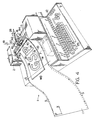
- Figure 1 is a perspective view illustrating the sign generating apparatus employed by the present invention.
- Figure 2 is a cross sectional view showing the tool head and the material advancing mechanism employed in the apparatus of Figure 1.
- Figures 3 is a side elevation view partially in section showing a knife blade tool and its associated support arm shown in Figure 2.
- Figure 4 is a perspective view illustrating the automatic weeding system embodying the present invention.
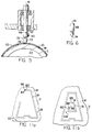
- Figure 5 is a side elevation view partially in section showing a pressure tool mounted in the support arm in place of the cutting tool of Figure 3.
- Figure 6 is a fragmentary side elevation view of the pressure tool of Figure 5 shown from another side.
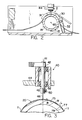
- Fig. 7 shows in side elevation view a pressing tool in contact with the overlay sheet and the sign web being supported on a fragmentary vertical section view of the support roller.
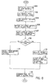
- Fig. 8 is a flowchart of the program followed by the controller for accomplishing the weeding process.
- Figure 9 is a view showing the automatic weeding of the sheet of sign material by the overlay sheet once bonded to it.
- Figure 10 is an alternative embodiment showing in side elevation view a knife and knife holder assembly including a fragmentary vertical section view of the material being bonded on the support roller.
- Figs. 11a and 11b illustrate the orientation of the pressure foot relative to the knife during the second pass made by the assembly of Fig. 10.
- Figure 12 is an alternative embodiment of the web of sign material in this case having the bonding means formed on its upper surface.
- Figure 13 is a sectional view through the web shown in Fig. 12.
- Figure 14 is a side elevation view partially in section of an alternative embodiment showing a liquid applicator mounted in the support arm in place of the cutting tool of Figure 3.
- a sign making machine 12 is illustrated for handling and working on an associated web 11 of laminated sheet material.
- the web 11 is moved through the machine 12 longitudinally of itself in the illustrated X coordinate direction by material advancing means 2 across a work surface defined by a roller 20.
- a tool head is supported and driven by appropriate motor means (not shown) in the illustrated Y coordinate direction on a way 13 extending transversely relative to the web 11.
- the machine 12 further includes a controller 7 having a microprocessing unit linked to a memory means and a keypad interface 25 for instructing the controller 7 to move the web 11 relative to the tool head 16 to cause a graphic 18 to be formed in the web 11.
- the advancing means includes two sprockets 14,14 rotatably driven by appropriate motor means about a common axis of rotation 65 in response to instructions issued by the controller 7.
- the sprockets 14,14 are spaced apart from one another by approximately the width of the web 11 and have a series of circumferentially disposed teeth or pins 15,15 projecting radially outwardly from the axis 65.
- the pins 15,15 are received within a series of openings 5,5 extending along either side edge of the web 11 in order to effect positive movement of the web 11 through the machine 12.
- Each of the sprockets has an associated arcuate clamp 31 joined with a pivotal support arm 30 biased toward the sprocket by a spring 32 drawing the clamp against the sheet material being pulled through the machine 12.
- the arcuately shaped guide clamps 31,31 each have an arcuate groove straddling the sprocket pins allowing the pins 15,15 to rotate through the clamps while nevertheless allowing each clamp to apply the hold down force necessary to keep the sheet material in registration with the sprockets.
- the tool head 16 carries a tool holder 40 and an associated tool rotatable relative to the head about an axis 41 oriented substantially vertically when the tool head is in the working position above the web 11 as illustrated in Fig. 1.
- a drive belt 42 is employed to rotatably couple the tool holder 40 to a motor carried by the tool head 16 responsive to commands issued by the controller 7.
- the tool head is pivotally mounted on the carriage 13 such that the tool holder 40 is cantilevered outwardly therefrom by an arm 44 allowing the holder and its associated tool to be normally urged downwardly toward the web 11 by gravity.
- a counterweight 26 is provided for varying the amount of downward pressure applied to the sheet material passing beneath the tool holder.
- the tool holder 40 has a chuck 48 for holding a cutting tool 46 for movement above the web 11 at the apex of the roller 20.
- the cutting tool 46 is a small scapula blade having a sharp cutting edge at its depending end and is clamped to the chuck 48 by means of a clamping screw 50 at its generally flat upper end.
- the chuck 48 and the associated cutting tool 46 are prevented from moving axially upwardly relative to the arm 44 by a detent ring 52 received within a circumaxial groove formed in the chuck 48.
- the chuck 48 is shown rotatably coupled by the belt 42, but may alternatively be freely rotatable about the tool axis 41 such that it is capable of repositioning itself along a line of cut as the directional movement of the web 11 is changed.
- the web 11 may be comprised of a sheet of sign material M and an underlying liner or base sheet L adhered to it.
- Each sheet has a relative thickness such that the materials allow the blade 46, with the appropriate adjustment of the counterweight 26, to cut the sheet material M while nevertheless only slightly scoring the liner L.
- the sign material sheet M has a cuttable upper sign surface 77 facing the tool head 16 and has an opposite lower surface 75 facing the liner sheet material L.
- the liner sheet material has an upper release surface R and an opposite lower surface 79 supportedly engaged by the roller 20.
- a layer T of pressure sensitive adhesive or permanently tacky adhesive releasably adhered to the release surface R of the liner sheet L, yet more strongly bonded to the lower surface 75 of the sign material sheet M.
- the adhesive layer T is however sufficiently strong enough to bond the cut graphic to a substrate surface in a manner consistent with that disclosed in the aforementioned U.S. Patent 4,467,525 issued to Logan et al.
- an automated weeding system indicated generally as 1 in Figure 4 is employed for readily removing weed portions W of the sign material sheet M from around and within the graphic 18 cut in it.
- the system 1 includes the aforementioned machine 12 which initially cuts the graphic 18 into the web 11, an overlay sheet 10 having means for placing it in registration with the cut web 11, a means 70 carried by the tool holder 40 for selectively bonding the overlay sheet 10 with portions of the sheet material M and a means within the controller 7 for causing the means 70 to follow a path slightly offset from the cut lines defining the graphic 18.
- the means 70 includes a pressing tool 72 having a depending tip 74 for engaging with the overlay sheet 10 to press it into bonding relationship with the underlying sign material sheet M in a manner that will be hereinafter become apparent.
- the pressing tool 72 at its upper end is sized to be received within the chuck 48 and may readily replace the cutting tool 46 by loosening the clamping screw 50 and reinserting the pressing tool 72 in its place.
- the overlay sheet 10 Interposed between the overlay sheet 10 and the web 11 is a bonding means 71 for selectively bonding to the overlay sheet 10 portions of the sign material sheet M directly underlying the tip 74 of the pressure tool 72.
- the overlay sheet 10 as illustrated in Fig. 7 may be comprised of a backing material O, preferably inexpensive paper having an upper surface 73 facing the tool 72 and an opposite lower surface 76 having a tacky adhesive layer A bonded to it.
- the adhesive layer A is a generally low tack adhesive with enough strength to hold the backing material O in place on the sign material sheet M.
- the adhesive layer A allows overlay sheet 10 to be held in registration with the web once it is placed onto the web for unitary movement therewith through the machine 12 as will hereinafter become apparent.
- each microsphere Embedded within the adhesive layer A however are a plurality of hollow microspheres C, within each is encapsulated a much stronger adhesive.
- each microsphere could contain a catalyst for activating the otherwise low tack adhesive layer A into an enhanced holding adhesive.
- the microspheres C contain a separate stronger adhesive and are of the type commercially available through the 3M Corporation having an 80% total weight payload fill of adhesive and a 20% total weight content comprised of shell.
- microspheres C are particularly well adapted for the purpose of automatic weeding because the microspheres C are crushable under the pressure tool 72 to effect enhanced bonding between the sheets O and M in regions exclusively beneath the tip 74 as can be appreciated from Figure 7.
- the relative adhesive bonding strengths and material thicknesses involved are selected such that the graphic 18 will remain adhered to the liner L while the weed portions W comprising the remaining sign material sheet M are pulled away with the overlay sheet 10 as will be discussed in greater detail with reference to Fig. 9.
- the controller 7 determines a point along the length of the web 11, illustrated as position S in Fig. 4, for the purpose of moving the web in either direction relative to it.
- the point S coincides with the place where the cutting tool begins cutting the graphic 18 into the web 11 (step 100).
- the cutting tool 46 is made to follow a preprogrammed first path along the web 11 to cut the graphic 18 into the sign material sheet M (step 102) in the manner discussed previously with reference to Fig. 1.
- the vectors used in creating the involved graphic 18 are stored in memory (step 104) for later use.
- the controller 7 then instructs the material advancing means 2 to reverse the direction of the web 11 to position the initialization point S in registry with the cutting tool 46 (step 106). While maintaining registration of the web 11 with the sprockets 14,14, the overlay sheet 10 is placed down on the sign material sheet M (step 107) such that it completely covers the graphic 18 cut into the sign material sheet M. Since the overlay sheet width WD is shorter than that of the web 11, by for example approximately 2 inches, it does not interfere with the advancing means sprockets 31,31 thus allowing the adhesive layer A to maintain both the web 11 and the overlay sheet 10 in registration with one another for unitary movement through the machine 12.
- the controller 7 causes the pressure tool 72 to follow a second path 19 along the upper surface 73 of the sheet O slightly offset from the cut lines defining the pattern 18 made in the web 11 as shown in phantom line in Fig. 4.
- the controller 7 recalls from memory, a standard offset software program (step 110) and uses it to alter the basic vectors from which the graphic 18 was originally cut (step 112) thereby causing the tool 72 to be moved along the second path 19.
- a standard offset software program step 110
- the tool 72 follows a path just slightly inwardly offset from the interior perimeter defining the opening.
- the pressure tool 72 is moved about the outer perimeter of the graphic 18 outwardly offset from the cut lines defining the graphic 18. In so doing, the tool 72 crushes selected ones of the underlying microcapsules C embedded in the adhesive layer A during its second pass over the web 11 (step 116) thus bonding the overlay sheet 10 to the weed portions W of the sign material sheet M in the region B just below the path 19 as best illustrated in Fig. 7.
- Fig. 10 shows an alternative embodiment of the cutting tool which may be employed by the weeding system 1.
- a combination pressure foot and knife holder assembly illustrated generally as 80 is used in place of the tool 72 thus avoiding the need to substitute the pressure tool 72 for the cutting implement 46.
- the assembly 80 is one such as disclosed in U.S. Patent No. 4,732,069 issued to Wood et al. on March 22, 1988 which patent being commonly assigned with the assignee of the present invention.
- the tool assembly 80 allows the graphic vectors stored in memory at step 104 to be recalled and used without alteration (step 114) to retrace the graphic 18 on the overlay sheet 10 thus mechanically creating the offset path 19.
- the assembly 80 comprises a body portion 89 having a depending portion 82 carrying a knife 84 and a pressure foot 86 offset laterally relative to the knife 84.
- the tip 88 of the knife projects downwardly from the pressure foot 86 by approximately 0.004 to 0.005 inch as indicated by the dimension Z. Because the tip 88 of the knife does not penetrate through or even substantially through the overlay sheet 10, the pressure foot 86 can thus be used to activate the underlying microcapsules C without causing the sheet O to be unduly cut up as the tool assembly 80 makes its second pass (step 116).
- Figs. 11a and 11b the presser foot 86 and the knife 84 are shown schematically as they are arranged on the tool assembly 80 in order to illustrate the positional relationship between these elements as the assembly 80 retraces the graphic 18 onto the overlay sheet O (step 116).
- the assembly 80 when tracing the outer perimeter of a shape, the assembly 80 is moved along a path 81 in a counterclockwise direction CC directly over the outer cut lines defining the graphic 18 such that the pressure foot 86 tracks along the outside edge of the shape.
- Fig. 11a when tracing the outer perimeter of a shape, the assembly 80 is moved along a path 81 in a counterclockwise direction CC directly over the outer cut lines defining the graphic 18 such that the pressure foot 86 tracks along the outside edge of the shape.
- the web 11′ is comprised of a liner or base sheet L′ bonded to a modified sheet of sign material M′.
- the sign material sheet M′ has an upper surface 134 and an opposite lower surface 140 defining the good or the sign face of the sheet.
- the liner sheet L′ has a layer of pressure sensitive or permanently tacky adhesive T′ bonded more strongly to it than to the sign surface 140 of the sign material sheet M′.
- the sign surface 140 serves as a release surface allowing the adhesive layer T′ to remain with the liner L′ when the sign material sheet M′ is pulled from it.
- the dry activatable adhesive K may take the form of a number of different types of activatable adhesives.
- the layer K is preferably a cured adhesive in which are embedded a plurality of crushable microcapsules of the type C disclosed with reference to Figure 7 above.
- the web 11′ is preferably of the type disclosed in copending U.S. Serial No. 056,458, entitled SIGN MAKING WEB WITH DRY ADHESIVE LAYER AND METHOD OF USING THE SAME filed on May 29, 1987 in the name of the same inventor of the present invention and being commonly assigned therewith.
- the graphic 18′ is cut into the sign material sheet M′ according to steps (100) through (102) discussed above. Since an activatable adhesive layer K is already bonded to the surface 134 of the sign material sheet M′, it is therefore not necessary to provide another such adhesive on the sheet O. However, the lower surface 76′ of the sheet O has a layer of tacky adhesive A′ for maintaining registration of the overlay sheet 10′ with the web 11′ once the adhesive layer A′ is placed down into contact on the dry adhesive surface K. Particularly well adapted for cutting and weeding of the graphic 18′ formed in the web 11′ is the replaceable tool arrangement of Figs. 3 and 5. As previously discussed, the graphic 18′ is cut in the web 11′ by the cutting tool 46, thereafter replaced by the pressing implement 72.
- the steps (110), (112) and (116) discussed previously with respect to Fig. 8 are then followed by the controller 7 causing the pressing tool 72 to be moved along the path 19′.
- the sign material defining the cut graphic may then be applied directly to the sign surface using the base sheet L according to the method disclosed in the aforementioned copending U.S. Application Serial No. 056,458.
- the dry activatable adhesive layer may alternatively take the form of an adhesive layer K′ capable of being transformed into a tacky state by applying a liquid to it. As shown in Fig. 14, an applicator 90 having a depending tip 91 is filled with a liquid tackifier and replaces the cutting tool 46 for this purpose. While the activatable adhesive layer K′ in this embodiment may take the form of a variety of different adhesives, the dry adhesive layer is preferably either rubber based or is water soluble.
- the applicator 90 is filled with a water based solution and in the example where the adhesive is rubber based, the applicator may be filled with a chemical tackifier, such as KODAFLEX Tx1B commercially made available by the Eastman Kodak Co., or other suitable activators, such as a di-2-ethyl hexyl phthalate solution.
- a chemical tackifier such as KODAFLEX Tx1B commercially made available by the Eastman Kodak Co.
- activators such as a di-2-ethyl hexyl phthalate solution.
- the applicator 90 when applying the tackifier in the manner shown in Fig. 14 follows the offset path created within the controller 7 as described with reference to step 112 in Fig 8.
- the tip 91 of the applicator 90 directly contacts the adhesive layer K′ to activate it along underlying portions thereby forming a path 19′ of tacky adhesive adjacent the graphic 18′.
- the overlay sheet O′ need only be comprised of a sheet of material, preferably paper, having a sufficient size to be placed over the graphic 18 to bond it with the weed portions of the sign material sheet M′ and to consequently allow the overlay sheet O to peel the weed portions from the liner L′ when the two sheets are pulled apart.
- the adhesive layer K′ in its tacky condition possesses a greater per unit peel strength taken relative to that of the tacky adhesive layer T′ in accordance with the relative strengths set forth in table A-1 above.
- the automatic weeding system embodying the present invention employs the sign generating machine 12 and associated software for causing the holder 40 and the implement carried by it to be moved relative to the work surface 20 to not only cut a desired graphic into the web 11,11′, but also to selectively tackify portions of the bonding means 71 into an activated adhesive.
- An overlay sheet 10 is provided for cooperating with the tackified portions of the bonding means such that the weed portions of the web 11 become bonded to the overlay sheet 10 for subsequent removal by the user.
- the overlay sheet 10 is either placed on the web 11 prior to the second pass made by a pressure tool as shown in Fig.
- the holder 40 may either carry two separate tools, one for cutting the web and the other for subsequently activating the bonding means 71 as illustrated in Figs. 5 and 6, or may carry a single tool which both cuts and activates without requiring tool replacement as is apparent from Fig 10.
- the overlay sheet 10,10′ is used for removing the unwanted portions of the sign material sheet M,M′ by pulling material which surrounds the graphic off the liner sheet material, it is possible to alternatively reverse the offset path followed by the pressure foot or tool so that the text adheres to the overlay sheet rather than to the weed portion so that it can be lifted off the backing leaving the weed on the original liner.
- the microencapsulated adhesive C is disclosed as being the preferred bonding means, it is entirely within the scope of the invention to substitute other known adhesives for this, such as for example, a thermally activated adhesive activated to a tacky condition by a heating element carried by the tool holder 40.
- the tool 72 may alternatively be an ultrasonic device moved along the overlay sheet in place on the sign material sheet to weld the two sheets together along a path.
Landscapes
- Life Sciences & Earth Sciences (AREA)
- Forests & Forestry (AREA)
- Engineering & Computer Science (AREA)
- Mechanical Engineering (AREA)
- Lining Or Joining Of Plastics Or The Like (AREA)
- Control Of Cutting Processes (AREA)
- Details Of Cutting Devices (AREA)
- Treatment Of Fiber Materials (AREA)
- Catching Or Destruction (AREA)
- Control And Other Processes For Unpacking Of Materials (AREA)
- Adhesive Tapes (AREA)
- Agricultural Chemicals And Associated Chemicals (AREA)
Claims (23)
- Vorrichtung zum Abtrennen von überschüssigem Material rund um eine Grafik (18), die in einen Zeichenmaterialbogen (M) mit einer Oberseite (77) und einer Unterseite (75) eingeschnitten ist, der lösbar an einem darunterliegenden Basisschichtbogen (L) befestigt ist, wobei das System umfaßt:
eine Auflage (20), eine auf der Auflage vorgesehene Arbeitsfläche, eine mit der Arbeitsfläche zusammenwirkende Vorschubeinrichtung (2) zur Bewegung des Zeichenmaterialbogens (M) über die Arbeitsfläche in einer zu deren Länge parallelen Richtung (X);
Haftmittel (71) auf dem Zeichenmaterialbogen (M) zur selektiven haftenden Verbindung von Bereichen des geschnittenen Zeichenmaterialbogens (M) mit einer Trägerfläche;
wobei das Haftmittel über eine Haftfestigkeit verfügt, die ausreicht, um den Zeichenmaterialbogen (M) von dem darunterliegenden Basisschichtbogen (L) abzuziehen;
eine Werkzeugeinrichtung (74, 86, 91), die relativ zur Arbeitsfläche bewegbar ist für das Zusammenwirken mit dem Haftmittel, um die genannten Bereiche des Zeichenmaterialbogens (M) in Abhängigkeit von den Bewegungen der Werkzeugeinrichtung mit der Trägerfläche haftend zu verbinden;
gekennzeichnet durch:
einen Auflagebogen (10), der eine Oberseite (73) und eine dieser abgewandte, dem Zeichenmaterialbogen (M) zugewandte Unterseite (76) hat und als Einheit mit dem Zeichenmaterialbogen (M) auf diesem aufliegend über die Arbeitsfläche bewegbar ist;
und durch eine Steuereinrichtung (7), die mit der Vorschubeinrichtung (2) und mit der Werkzeugeinrichtung (74, 86, 91) verbunden ist zum Koordinieren der Bewegung zwischen der Werkzeugeinrichtung (74, 86, 91) und der Vorschubeinrichtung (2) derart, daß die Werkzeugeinrichtung (74, 86, 91) automatisch einer versetzten Bahn (19) entlang des Umfangs der in den Zeichenmaterialbogen (M) eingeschnittenen Grafik (18) folgt, mit dem Ergebnis, daß das Haftmittel den Auflagebogen (10) selektiv mit den überschüssigen Bereichen (W) des Zeichenmaterialbogens (M) haftend verbindet. - Vorrichtung nach Anspruch 1, ferner dadurch gekennzeich net, daß das Haftmittel (71) zwischen dem Auflagebogen (10) und dem Zeichenmaterialbogen eingebracht ist und einen mikroverkapselten Klebstoff (C) enthält, der durch die Werkzeugeinrichtung über eine nach unten ausgeübte Kraft aktiviert wird.
- Vorrichtung nach Anspruch 2, ferner dadurch gekennzeich net, daß das Haftmittel (71) durch eine Schicht aus einem schwach klebrigen Dauerklebstoff (A), dessen Haftfestigkeit pro Einheit geringer ist als die des Haftmittels, an der Unterseite (76) des Auflagebogens (10) befestigt ist;
daß der Auflagebogen (10) durch diese Schicht des schwach klebrigen Dauerklebstoffs auf dem Zeichenmaterialbogen befestigt ist, um den Auflagebogen in deckender Übereinstimmung mit dem Zeichenmaterialbogen zu halten, wenn die Werkzeugeinrichtung die nach unten wirkende Kraft ausübt; und daß die Mikrokapseln in die schwach klebrige Dauerklebstoffschicht eingebettet sind. - Vorrichtung nach einem der vorhergehenden Ansprüche, ferner dadurch gekennzeichnet, daß die Werkzeugeinrichtung einen Werkzeughalter (40) enthält, der sich relativ zur Bewegungsrichtung des Zeichenmaterialbogens über die Arbeitsfläche bewegen kann;
und daß der Werkzeughalter ein Druckwerkzeug mit einem nach unten ragenden Abschnitt (74) hält, der eine Druckspitze für den Angriff an dem Auflagebogen und für dessen Beaufschlagung mit einer nach unten gerichteten Kraft bildet und dadurch den aktivierbaren Klebstoff entlang der Bahn (19) aktiviert, die von der in den Zeichenmaterialbogen eingeschnittenen Grafik versetzt ist. - Vorrichtung nach Anspruch 4, ferner dadurch gekennzeich net, daß der Werkzeughalter ein Spannfutter (48) mit einem Festspannelement (50) hat zum Austausch des Druckwerkzeugs gegen ein Schneidmesser (46), das zum Einschneiden der Grafik in den Zeichenmaterialbogen verwendet wird;
und daß der Werkzeughalter relativ zur Halteeinrichtung schwenkbar montiert ist (16) und Einstellmittel (26) zur Einstellung der Größe der von dem Druckwerkzeug (72) ausgeübten nach unten gerichteten Kraft besitzt. - Vorrichtung nach einem der vorhergehenden Ansprüche, ferner dadurch gekennzeichnet, daß der Zeichenmaterialbogen und der Basisschichtbogen eine erste und eine zweite Reihe von Öffnungen (5, 5) haben, wobei sich die Öffnungen der ersten Reihe entlang einer Längskante des Zeichenmaterialbogens und des Basisschichtbogens und die Öffnungen der zweiten Reihe entlang der anderen, gegenüberliegenden Kante jedes Bogens befinden;
daß jede Öffnung in der ersten Reihe in Querrichtung mit einer entsprechenden Öffnung in der zweiten Reihe fluchtet;
und daß die Vorschubeinrichtung zwei voneinander beabstandete, um eine gemeinsame Drehachse (65) drehbare Stacheltransporträder (14, 14) hat, deren jedes mit mehreren sich radial erstreckenden und in Umfangsrichtung beabstandeten Zapfen (15, 15) versehen ist, die um jedes Stacheltransportrad herum in identischer Weise angeordnet sind und in Übereinstimmung damit jeweils entsprechende Öffnungspaare der ersten und der zweiten Reihe aufnehmen. - Vorrichtung nach einem der vorhergehenden Ansprüche, ferner dadurch gekennzeichnet, daß das Druckwerkzeug ein Drückerfuß (86) ist, der von dem Werkzeughalter als Teil eines Werkzeugsystems (80) gehalten wird;
daß das Werkzeugsystem (80) eine Schneidklinge (84) hat, die an den Drückerfuß angrenzend angeordnet und relativ zu diesem seitlich versetzt ist;
daß die Schneidklinge eine Spitze (88) hat, die von dem Drückerfuß über eine erste gegebene Distanz nach unten ragt;
und daß der Auflagebogen (10) eine zwischen der Oberseite (73) und der Unterseite (76) gemessene Dicke hat, die größer ist als die erste gegebene Distanz, so daß die Spitze den Auflagebogen nicht durchdringt, wenn der Drückerfuß entlang der Oberfläche des Auflagebogens bewegt wird. - Vorrichtung nach Anspruch 7, ferner dadurch gekennzeich net, daß die Steuereinrichtung Mittel (7) umfaßt, die bewirken, daß das Werkzeugsystem entlang der Oberseite (73) des Auflagebogens in einer Richtung gegen den Uhrzeigersinn bewegt wird (Figur lla), wenn das Werkzeugsystem der äußeren Begrenzung der in den Zeichenmaterialbogen eingeschnittenen Grafik folgt, um das relativ zu der äußeren Begrenzung der Grafik nach außen versetzte Druckwerkzeug auszurichten;
und daß diese Mittel weiterhin bewirken, daß das Werkzeugsystem entlang der Oberseite des Auflagebogens in einer dem Uhrzeigersinn folgenden Richtung bewegt wird (Figur 11b), wenn das Werkzeugsystem inneren Begrenzungen der in den Zeichenmaterialbogen eingeschnittenen Grafik folgt, um das Druckwerkzeug relativ zu einer inneren Begrenzung versetzt auszurichten, welche die Grafik definieren kann. - Vorrichtung nach einem der vorhergehenden Ansprüche, ferner dadurch gekennzeichnet, daß das Haftmittel (K) an der Oberseite des geschnittenen Zeichenmaterialbogens gebildet ist.
- Vorrichtung nach Anspruch 9, ferner dadurch gekennzeich net, daß das Haftmittel ein mikroverkapselter Klebstoff (C) ist, der in eine Trockenklebstoffschicht eingebettet ist, die an der Oberseite des Zeichenmaterialbogens gebildet ist.
- Vorrichtung nach Anspruch 10, ferner dadurch gekennzeich net, daß die Werkzeugeinrichtung einen Werkzeughalter enthält, der sich relativ zur Arbeitsfläche bewegen kann;
und daß der Werkzeughalter des weiteren ein Druckwerkzeug (74, 86) mit einem nach unten ragenden Abschnitt enthält, der eine Druckspitze bildet, die auf die Oberseite des Auflagebogens aufgesetzt werden kann, um auf den Auflagebogen eine nach unten gerichtete Kraft auszuüben und um danach das unter ihm angeordnete Haftmittel zu aktivieren. - Vorrichtung nach Anspruch 11, ferner dadurch gekennzeich net, daß die Steuereinrichtung Mittel enthält, die bewirken, daß die Druckspitze einer Bahn (19′) entlang der Oberseite des Auflagebogens folgt, die von der äußeren Begrenzung der Grafik nach außen versetzt ist (Figur 11a) und die von einer inneren Begrenzung der Grafik, welche eine Öffnung in der Grafik begrenzen kann, nach innen versetzt ist (Figur 11b).
- Vorrichtung nach Anspruch 12, ferner dadurch gekennzeich net, daß der Zeichenmaterialbogen durch einen den Basisschichtbogen kaschierenden permanent klebrigen Klebstoff (T′) lösbar an dem darunterliegenden Material (L′) des Basisschichtbogens befestigt ist;
daß der permanent klebrige Klebstoff eine Haftfestigkeit pro Einheit hat, die geringer ist als die des Haftmittels, wenn letzteres aktiviert ist;
und daß die Unterseite (140) des Zeichenmaterialbogens die Zeichenfläche definiert, dem Basisschichtbogen zugewandt und mit der Schicht des permanent klebrigen Klebstoffs konfrontiert ist. - Vorrichtung nach Anspruch 1, ferner dadurch gekennzeich net, daß das Haftmittel an der Oberseite des Zeichenmaterialbogens (Figur 14) gebildet ist und aus einer Trockenklebstoffschicht (K′) besteht, deren klebriger Zustand durch eine Flüssigkeit aktiviert werden kann;
daß der Zeichenmaterialbogen (M′) durch eine permanent klebrige Klebstoffschicht (T′), die stärker an dem Basisschichtbogen haftet als an der Unterseite des Zeichenmaterialbogens, lösbar an dem darunterliegenden Material des Basisschichtbogens (L′) befestigt ist;
daß der permanent klebrige Klebstoff eine Haftfestigkeit pro Einheit hat, die geringer ist als die des Haftmittels, wenn dieses aktiviert ist;
daß die Werkzeugeinrichtung einen Halter hat, der sich quer zur Bewegungsrichtung des Zeichenmaterialbogens über die Arbeitsfläche bewegen kann;
und daß der Werkzeughalter des weiteren einen Applikator (90) für Flüssigkeit trägt, dessen nach unten abstehende Spitze (91) auf die Trockenklebstoffschicht aufgesetzt werden kann, um selektiv einen flüssigen Aktivator auf die Trockenklebstoffschicht aufzutragen. - Vorrichtung nach Anspruch 14, ferner dadurch gekennzeich net, daß die Steuereinrichtung (7) ein Mittel enthält, welches bewirkt, daß die nach unten abragende Spitze des Applikators entlang der Trockenklebstoffschicht einer Bahn folgt, die von den äußeren Begrenzungen der Grafik nach außen und von einer inneren Begrenzung, die eine Öffnung in der Grafik begrenzen kann, nach innen versetzt ist.
- Verfahren zum Abtrennen von überschüssigem Material innerhalb einer Grafik und um die Grafik herum, die in eine Bahn (11) aus einem Zeichenmaterial in Form eines Bogens eingeschnitten ist, wobei das Verfahren folgende Schritte umfaßt:
Bereitstellen eines Zeichenmaterialbogens (M) mit einer Oberseite (77) und einer gegenüberliegenden Unterseite (75), wobei die Unterseite (75) des Zeichenmaterialbogens (M) durch eine Schicht aus einem permanent klebrigen Klebstoff (T) lösbar an einem Basisschichtbogen (L) befestigt wird,
Einschneiden von Linien (18) in den Bogen des Zeichenmaterials (11), um eine Grafik zu bilden;
Bereitstellen einer Trägerfläche;
Herstellen des Kontakts der Trägerfläche mit der Oberseite (77) des Zeichenmaterialbogens (M), nachdem der Einschnitt in den Bogen des Zeichenmaterials (11) erfolgt ist;
Haftende Verbindung von Bereichen des geschnittenen Zeichenmaterialbogens (M) mit der Trägerfläche;
und Trennen der haftenden Bereiche des Zeichenmaterialbogens (M) von dem restlichen Zeichenmaterial;
gekennzeichnet durch
das Bereitstellen eines Auflagebogens (10) mit einer Oberseite (73) und einer dieser abgewandten unteren Trägerfläche (76);
wobei der Schritt der haftenden Verbindung von Bereichen des Bogens des geschnittenen Zeichenmaterials (11) mit dem Auflagebogen (10) ferner die folgenden Schritte enthält:
die Bereitstellung eines Haftmittels (C, K, K′), das bereichsweise zwischen einem nichtklebrigen Zustand und einem klebrigen Zustand aktiviert werden kann;
Einbringen des Haftmittels (C, K, K′) zwischen die Unterseite (76) des Auflagebogens (10) und die Oberseite des Bogens des Zeichenmaterials (11), indem der Auflagebogen (10) auf der Oberseite des Zeichenmaterialbogens (M) angeordnet wird;
Aktivieren von Bereichen des Haftmittels (C, K, K′), die von den Schnittlinien (18, 18′), welche das in dem Zeichenmaterialbogen gebildete Grafikzeichen begrenzen, etwas versetzt sind (19, 19′), unter Verwendung einer automatisierten Einrichtung (1);
und Abziehen des Auflagebogens (10) von dem Basisschichtbogen (L) zusammen mit den überschüssigen Bereichen (W) des Bogens des geschnittenen Zeichenmaterials (11), der an dem Auflagebogen (10) haftet. - Verfahren nach Anspruch 16, ferner dadurch gekekennzeich net, daß die automatisierte Einrichtung (1) Werkzeuge für das automatische Einschneiden des Grafikzeichens in den Zeichenmaterialbogen bereitstellt;
daß in der automatisierten Einrichtung Steuermittel (7) vorgesehen werden, die bewirken, daß die Werkzeuge das Grafikzeichen automatisch in den Zeichenmaterialbogen einschneiden (Schritt 102) und daß die zum Einschneiden des Grafikzeichens verwendeten Vektoren danach gespeichert werden (Schritt 104);
und daß die gespeicherten Vektoren verwendet werden (Schritt 110), um die Werkzeuge an einer Bahn entlang zu bewegen, die etwas versetzt ist von den Linien, die das in den Zeichenmaterialbogen eingeschnittene Grafikzeichen begrenzen (Schritt 112). - Verfahren nach Anspruch 17, ferner dadurch gekennzeichnet, daß das Haftmittel in Form eines mikroverkapselten Klebstoffs (C) bereitgestellt wird;
daß der mikroverkapselte Klebstoff in eine schwach klebrige Klebstoffschicht (A) eingebettet und diese mit der Unterseite des Auflagebogens (10) haftend verbunden wird; daß die Werkzeugeinrichtung in Form eines Druckwerkzeugs (72) bereitgestellt wird;
und daß das Druckwerkzeug auf die Oberseite des Auflagebogens aufgesetzt wird, um den verkapselten Klebstoff zusammenzudrücken und den klebrigen Zustand in Bereichen desselben zu aktivieren (Figur 7). - Verfahren nach Anspruch 18, ferner dadurch gekennzeichnet, daß die den Basisschichtbogen (L) überlagernde Schicht aus dem permanent klebrigen Klebstoff (T) mit der Unterseite (75) des Zeichenmaterialbogens stärker haftend verbunden wird als mit dem Basisschichtbogen;
daß die schwach klebrige Klebstoffschicht (A) des Auflagebogens mit einer ersten gegebenen Ablösefestigkeit versehen wird;
daß die aktivierten Bereiche (C) des Haftmittels mit einer zweiten Ablösefestigkeit versehen werden, die wesentlich größer ist als die erste Ablösefestigkeit;
und daß der Zeichenmaterialbogen mit dem Auflagebogen von dem Basisschichtbogen derart abgelöst wird, daß die eingeschnitte Grafik an dem Basisschichtbogen haften bleibt, während die restlichen Bereiche des geschnittenen Zeichenmaterialbogens an dem Auflagebogen haften (Figur 9). - Verfahren nach einem der Ansprüche 16 bis 19, ferner dadurch gekennzeichnet, daß eine Werkzeugeinrichtung (Figur 10) bereitgestellt wird, die eine Schneidklinge mit einer nach unten abragenden Spitze (88) und einen von dieser versetzten Drückerfuß (86) hat;
daß der Auflagebogen (10) mit einer ersten gegebenen Dicke und die Messerspitze mit einer Eindringtiefe (Z) versehen wird, die relativ zu dem Drückerfuß eine zweite gegebene Distanz definiert;
und daß die erste Dicke derart gewählt wird, daß sie größer ist als die zweite gegebene Distanz, so daß das Messer nur teilweise in den Auflagebogen über den Drückerfuß hinaus schneidet. - Verfahren nach Anspruch 20, ferner dadurch gekennzeichnet, daß die Werkzeugeinrichtung beim Abfahren des äußeren Umfangs einer geschlossenen Form gegen den Uhrzeigersinn bewegt wird (Figur 11a);
und daß die Werkzeugeinrichtung, wenn sie dem inneren Umfang einer innerhalb der geschlossenen Form gebildeten Öffnung folgt, im Uhrzeigersinn bewegt wird. - Verfahren nach einem der Ansprüche 16 bis 21, dadurch ge kennzeichnet,
daß ein Haftmittel in Form einer Schicht aus einem trocken aktivierbaren Klebstoff (K′) auf der Oberseite (77) des Zeichenmaterialbogens vorgesehen wird;
daß eine Schicht aus einem permanent klebrigem Klebstoff (T′) zwischen der Unterseite (75) des Zeichenmaterialbogens und der Oberseite des Basisschichtbogens eingebracht wird;
daß der aktivierte Zustand des trocken aktivierbaren Klebstoffs (K′) mit einer Ablösefestigkeit pro Einheit erzeugt wird, die wesentlich größer ist als die des permanent klebrigen Klebstoffs (T′);
daß ein Applikator (90) vorgesehen wird zum selektiven Aktivieren des aktivierbaren Klebstoffs (K′);
und daß der Applikator (90) mit der Schicht aus dem aktivierbaren Trockenklebstoff (K′) kontaktiert und entlang einer Bahn bewegt wird, die etwas versetzt ist von den die Grafik begrenzenden Schnittlinien (18,18′), um dessen Klebrigkeit entlang der Bahn zu bewirken. - Kaschierte Bahn, umfassend einen Bogen aus einem Basismaterial (L, L′) mit einer eine Unterseite (79) bildenden ersten Fläche und mit einer eine Oberseite (R) bildenen zweiten Fläche, einen Bogen aus einem Zeichenmaterial (M, M′) mit einer eine Unterseite (75) bildenden dritten Fläche und einer eine Oberseite bildenden vierten Fläche (77);
eine Schicht aus permanent klebrigem Klebstoff (T, T′), die zwischen der zweiten Fläche (R) des Bogens aus dem Basismaterial (L, L′) und der dritten Fläche (75) des Zeichenmaterialbogens (M, M′) eingebracht ist;
ein Haftmittel (C, K, K′) an der vierten Fläche (77) des Zeichenmaterialbogens (M, M′);
wobei das Haftmittel (C, K, K′) selektiv aus einem nicht klebrigen Zustand in einen klebrigen Zustand aktivierbar ist;
und wobei das Haftmittel (C, K, K′) im klebrigen Zustand eine Haftfestigkeit pro Einheit besitzt, die wesentlich größer ist als die Haftfestigkeit der Schicht aus permanent klebrigem Klebstoff (T, T′), so daß, wenn der Zeichenmaterialbogen (M, M′) durch das sich in klebrigem Zustand befindende Haftmittel (C,K,K′) mit einer Trägerfläche verbunden ist, Bereiche davon durch die Trägerfläche von dem darunterliegenden Basisschichtbogen (L, L′) abgezogen werden können;
gekennzeichnet durch
einen Auflagebogen (10), der eine eine Unterseite (76) bildende fünfte Fläche und eine eine Oberseite bildende sechste Fläche (73) hat und das Haftmittel (C, K, K′) in Ausrichtung mit dem Zeichenmaterialbogen (M, M′) überdeckt.
Applications Claiming Priority (3)
| Application Number | Priority Date | Filing Date | Title |
|---|---|---|---|
| US566123 | 1990-08-10 | ||
| US07/566,123 US5143576A (en) | 1990-08-10 | 1990-08-10 | Automatic weeding system and method of use |
| CA002056149A CA2056149C (en) | 1990-08-10 | 1991-11-25 | Automatic weeding system and method of use |
Publications (2)
| Publication Number | Publication Date |
|---|---|
| EP0470645A1 EP0470645A1 (de) | 1992-02-12 |
| EP0470645B1 true EP0470645B1 (de) | 1994-06-29 |
Family
ID=25674868
Family Applications (1)
| Application Number | Title | Priority Date | Filing Date |
|---|---|---|---|
| EP91113470A Expired - Lifetime EP0470645B1 (de) | 1990-08-10 | 1991-08-09 | System zum Trennen von geschnittenen Produkten und Methode zur Anwendung |
Country Status (7)
| Country | Link |
|---|---|
| US (2) | US5143576A (de) |
| EP (1) | EP0470645B1 (de) |
| JP (1) | JPH07276B2 (de) |
| AT (1) | ATE107883T1 (de) |
| AU (1) | AU630576B1 (de) |
| CA (1) | CA2056149C (de) |
| DE (1) | DE69102686T2 (de) |
Families Citing this family (30)
| Publication number | Priority date | Publication date | Assignee | Title |
|---|---|---|---|---|
| US5288358A (en) * | 1987-05-29 | 1994-02-22 | Gerber Scientific Products, Inc. | Sign making web with dry adhesive layer and method of using the same |
| AU650636B2 (en) * | 1990-02-05 | 1994-06-30 | Molins Plc | Image applying method and apparatus |
| US5240539A (en) * | 1992-02-19 | 1993-08-31 | New Hermes Incorporated | Process for making three-dimensional signage |
| DE4307889C2 (de) * | 1993-03-12 | 1997-04-10 | Axel Donat | Verfahren zum automatischen Entgittern und Übertragen computergeschnittener Selbstklebefolien und Folie zur Durchführung des Verfahrens |
| US5695600A (en) * | 1994-10-03 | 1997-12-09 | Goin; Bobby Gene | Vacuum table for decal weeding |
| DE59701935D1 (de) * | 1996-02-24 | 2000-08-03 | Kurz Leonhard Fa | Verfahren zur herstellung einer prägefolie |
| US6102096A (en) * | 1997-05-30 | 2000-08-15 | Johansson; Goeran | Method and device for applying a pattern onto a support means |
| US6106645A (en) * | 1998-01-21 | 2000-08-22 | Gerber Scientific Products, Inc. | Method and apparatus for manufacturing a graphic product |
| ES2188439T3 (es) * | 2000-03-02 | 2003-07-01 | Gerber Scient Products Inc | Procedimiento y dispositivo para fabricar productos graficos. |
| USD453179S1 (en) | 2000-07-27 | 2002-01-29 | Iimak | Printer cassette |
| USD458295S1 (en) | 2000-07-27 | 2002-06-04 | Iimak | Printer cassette |
| US6582801B1 (en) | 2000-08-03 | 2003-06-24 | Optima Graphics, Inc. | Signage with opaque and transparent elements and method of making the same |
| US20020108477A1 (en) * | 2001-02-09 | 2002-08-15 | Seniff Dana W. | Method for cutting coating blankets from sheet-type work material |
| US6797103B2 (en) | 2001-03-12 | 2004-09-28 | Mikkelsen Graphic Engineering Inc. | Automatic waste-area removal method and apparatus |
| US6830645B2 (en) * | 2001-03-26 | 2004-12-14 | Appleton Papers Inc. | System and method for rupturing encapsulated adhesive in sheet media |
| EP1372961B1 (de) * | 2001-03-26 | 2007-09-19 | Appleton Papers Inc. | System und verfahren zum aufbrechen von verkapseltem klebstoff in flächengebilden |
| US7250092B2 (en) * | 2001-12-05 | 2007-07-31 | Ferrell Randall W | Adhesive sign and methods for applying and producing same |
| AT6638U1 (de) * | 2002-10-01 | 2004-01-26 | Gfm Gmbh | Verfahren zum ausschneiden eines zuschnittes aus einer textilen warenbahn zum herstellen von werkstücken aus einem faser-kunststoffverbund |
| US7140283B2 (en) * | 2004-05-05 | 2006-11-28 | Mikkelsen Graphic Engineering | Automated method and apparatus for vision registration of graphics areas operating from the unprinted side |
| USD527761S1 (en) | 2005-02-17 | 2006-09-05 | International Imaging Materials, Inc. | Printer cassette |
| US7930958B2 (en) | 2005-07-14 | 2011-04-26 | Provo Craft And Novelty, Inc. | Blade housing for electronic cutting apparatus |
| US20070012146A1 (en) * | 2005-07-14 | 2007-01-18 | Robert Workman | Electronic paper cutting apparatus and method |
| US7845259B2 (en) * | 2005-07-14 | 2010-12-07 | Provo Craft And Novelty, Inc. | Electronic paper cutting apparatus |
| US20090000437A1 (en) * | 2005-07-14 | 2009-01-01 | Provo Craft And Novelty, Inc. | Methods for Cutting |
| US20090025869A1 (en) * | 2005-09-27 | 2009-01-29 | Contra Vision Limited | Method Of Making A Vision Control Panel Using Cut Film |
| US7682476B2 (en) * | 2006-03-27 | 2010-03-23 | Ralph Sutton | Method to create 3-dimensional images from a 2-dimensional image |
| US20110280999A1 (en) | 2009-12-23 | 2011-11-17 | Provo Craft And Novelty, Inc. | Foodstuff Crafting Apparatus, Components, Assembly, and Method for Utilizing the Same |
| JP2013193193A (ja) * | 2012-03-22 | 2013-09-30 | Brother Industries Ltd | 切断装置 |
| ITFI20120232A1 (it) * | 2012-10-29 | 2014-04-30 | Esanastri S R L | Dispositivo di macro-sfridatura di film plastici o in carta a uno o più strati autoadesivi, biadesivizzati o elettrostatici accoppiati con un liner di supporto antiaderente |
| ITFI20120233A1 (it) * | 2012-10-29 | 2014-04-30 | Esanastri S R L | Dispositivo di micro-sfridatura di film plastici o in carta a uno o più strati autoadesivi, biadesivizzati o elettrostatici accoppiati con un liner di supporto antiaderente |
Family Cites Families (19)
| Publication number | Priority date | Publication date | Assignee | Title |
|---|---|---|---|---|
| US2591779A (en) * | 1948-04-13 | 1952-04-08 | By Buk Company | Sign and method of making the same |
| DE1066687B (de) * | 1958-05-28 | 1900-01-01 | ||
| US3297508A (en) * | 1962-12-10 | 1967-01-10 | Meyercord Co | Dry strip decalcomania or transfer and method of use |
| DE1225490B (de) * | 1964-02-27 | 1966-09-22 | Heinrich Heichlinger | Material zur Herstellung von negativen Kopiervorlagen |
| US3741786A (en) * | 1971-05-28 | 1973-06-26 | Avery Products Corp | Transfer tape having non-contiguous pressure sensitive adhesive patterns |
| US3785898A (en) * | 1972-01-14 | 1974-01-15 | Gerber Garment Technology Inc | Apparatus for producing seamed articles from sheet material |
| GB2039785B (en) * | 1978-11-09 | 1983-04-13 | Sanyo Kokusaku Pulp Co | Pressure sensitive adhesive products and the method for preparation of the same |
| US4460634A (en) * | 1979-12-29 | 1984-07-17 | Masaaki Hasegawa | Adhesive sheet and method for manufacturing the same |
| GB2092521A (en) * | 1981-02-06 | 1982-08-18 | Letraset International Ltd | Production of artwork |
| US4444078A (en) * | 1982-02-04 | 1984-04-24 | Gerber Garment Technology, Inc. | Apparatus for cutting sheet material |
| US4448808A (en) * | 1982-04-15 | 1984-05-15 | Gerber Garment Technology, Inc. | Method for preparing pattern piece |
| US4467525A (en) * | 1982-07-26 | 1984-08-28 | Gerber Scientific Products, Inc. | Automated sign generator |
| US4512839A (en) * | 1982-10-29 | 1985-04-23 | Gerber Scientific, Inc. | Multi-color sign making method and layup |
| DE3501815C2 (de) * | 1985-01-21 | 1987-04-16 | D. Swarovski & Co., Wattens, Tirol | Verfahren zur Herstellung eines Dekormaterials |
| US4759816A (en) * | 1986-07-07 | 1988-07-26 | Schoeller Technical Papers, Inc. | Strippable film for adhesive coating and laminating |
| US4732069A (en) * | 1987-05-08 | 1988-03-22 | Gerber Scientific Products, Inc. | Knife and knife holder assembly |
| US5026584A (en) * | 1987-05-29 | 1991-06-25 | Gerber Scientific Products, Inc. | Sign making web with dry adhesive layer |
| US4824498A (en) * | 1987-07-09 | 1989-04-25 | James River Corporation | Strippalble sponge cushion underlay for a surface covering, such as carpeting |
| US5116439A (en) * | 1989-02-13 | 1992-05-26 | Sponge-Cushion, Inc. | Method and product for floor covering installation and removal |
-
1990
- 1990-08-10 US US07/566,123 patent/US5143576A/en not_active Expired - Lifetime
-
1991
- 1991-08-09 DE DE69102686T patent/DE69102686T2/de not_active Expired - Fee Related
- 1991-08-09 EP EP91113470A patent/EP0470645B1/de not_active Expired - Lifetime
- 1991-08-09 AT AT91113470T patent/ATE107883T1/de not_active IP Right Cessation
- 1991-08-12 JP JP3201918A patent/JPH07276B2/ja not_active Expired - Fee Related
- 1991-09-17 AU AU84561/91A patent/AU630576B1/en not_active Ceased
- 1991-11-25 CA CA002056149A patent/CA2056149C/en not_active Expired - Fee Related
-
1992
- 1992-06-09 US US07/895,929 patent/US5277736A/en not_active Expired - Fee Related
Also Published As
| Publication number | Publication date |
|---|---|
| CA2056149C (en) | 1996-10-22 |
| US5277736A (en) | 1994-01-11 |
| AU630576B1 (en) | 1992-10-29 |
| EP0470645A1 (de) | 1992-02-12 |
| CA2056149A1 (en) | 1993-05-26 |
| JPH04250996A (ja) | 1992-09-07 |
| US5143576A (en) | 1992-09-01 |
| JPH07276B2 (ja) | 1995-01-11 |
| ATE107883T1 (de) | 1994-07-15 |
| DE69102686T2 (de) | 1994-12-15 |
| DE69102686D1 (de) | 1994-08-04 |
Similar Documents
| Publication | Publication Date | Title |
|---|---|---|
| EP0470645B1 (de) | System zum Trennen von geschnittenen Produkten und Methode zur Anwendung | |
| GB2130419A (en) | Multi-color sign making | |
| US6106645A (en) | Method and apparatus for manufacturing a graphic product | |
| US4364330A (en) | Cutting apparatus with consumable marker | |
| JPS59124600A (ja) | パタ−ン片作成方法 | |
| JPS63300892A (ja) | ナイフ及びナイフホルダ組立体 | |
| EP0295458A2 (de) | Vorrichtung zum Entfernen von Graten von Gussprodukten | |
| US5304410A (en) | Cutting cloth web having mounted backing material and related method | |
| US20200349868A1 (en) | Multilayered sheet assembly and a method for forming a sign | |
| JPS62198890A (ja) | 標識作成用の多層ウエブとその使用方法 | |
| US5213656A (en) | Method of using a web for etching of a surface | |
| JPH0356227A (ja) | 熱接着フィルムの接着装置 | |
| IL268631A (en) | Digital methods and system for cutting and folding corrugated cardboard | |
| JP3524263B2 (ja) | 自動裁断機におけるマーキング方法およびマーキング装置 | |
| JPH07149034A (ja) | スタンプ装置 | |
| CA1309605C (en) | Method of producing grinding tool and apparatus for producing same | |
| EP1129867B1 (de) | Verfahren und Vorrichtung zur Herstellung eines graphischen Produkts | |
| JP6543043B2 (ja) | エンボス加工機 | |
| KR102911814B1 (ko) | 경사 가변 원뿔대 핫 스탬핑 장치 | |
| CA2056329A1 (en) | Sign making technique using double sided adhesive graphics and subsequently applied decorative layer | |
| KR20260038330A (ko) | 원뿔대 형상 제품의 핫스탬핑 방법 및 그 장치 | |
| US20020108477A1 (en) | Method for cutting coating blankets from sheet-type work material | |
| JP2506700B2 (ja) | 微小物体の自動供給方法 | |
| JP2756291B2 (ja) | マーク用布地等の切断装置 | |
| US6401616B1 (en) | Method and material for making a coating blanket for use in printing presses |
Legal Events
| Date | Code | Title | Description |
|---|---|---|---|
| PUAI | Public reference made under article 153(3) epc to a published international application that has entered the european phase |
Free format text: ORIGINAL CODE: 0009012 |
|
| 17P | Request for examination filed |
Effective date: 19911122 |
|
| AK | Designated contracting states |
Kind code of ref document: A1 Designated state(s): AT BE CH DE DK ES FR GB GR IT LI LU NL SE |
|
| 17Q | First examination report despatched |
Effective date: 19930316 |
|
| GRAA | (expected) grant |
Free format text: ORIGINAL CODE: 0009210 |
|
| AK | Designated contracting states |
Kind code of ref document: B1 Designated state(s): AT BE CH DE DK ES FR GB GR IT LI LU NL SE |
|
| PG25 | Lapsed in a contracting state [announced via postgrant information from national office to epo] |
Ref country code: NL Effective date: 19940629 Ref country code: LI Effective date: 19940629 Ref country code: GR Free format text: LAPSE BECAUSE OF FAILURE TO SUBMIT A TRANSLATION OF THE DESCRIPTION OR TO PAY THE FEE WITHIN THE PRESCRIBED TIME-LIMIT Effective date: 19940629 Ref country code: ES Free format text: THE PATENT HAS BEEN ANNULLED BY A DECISION OF A NATIONAL AUTHORITY Effective date: 19940629 Ref country code: DK Effective date: 19940629 Ref country code: CH Effective date: 19940629 Ref country code: BE Effective date: 19940629 |
|
| REF | Corresponds to: |
Ref document number: 107883 Country of ref document: AT Date of ref document: 19940715 Kind code of ref document: T |
|
| REF | Corresponds to: |
Ref document number: 69102686 Country of ref document: DE Date of ref document: 19940804 |
|
| ITF | It: translation for a ep patent filed | ||
| PG25 | Lapsed in a contracting state [announced via postgrant information from national office to epo] |
Ref country code: LU Free format text: LAPSE BECAUSE OF NON-PAYMENT OF DUE FEES Effective date: 19940831 |
|
| ET | Fr: translation filed | ||
| PG25 | Lapsed in a contracting state [announced via postgrant information from national office to epo] |
Ref country code: SE Effective date: 19940929 |
|
| REG | Reference to a national code |
Ref country code: CH Ref legal event code: PL |
|
| NLV1 | Nl: lapsed or annulled due to failure to fulfill the requirements of art. 29p and 29m of the patents act | ||
| PLBE | No opposition filed within time limit |
Free format text: ORIGINAL CODE: 0009261 |
|
| STAA | Information on the status of an ep patent application or granted ep patent |
Free format text: STATUS: NO OPPOSITION FILED WITHIN TIME LIMIT |
|
| 26N | No opposition filed | ||
| REG | Reference to a national code |
Ref country code: GB Ref legal event code: IF02 |
|
| PGFP | Annual fee paid to national office [announced via postgrant information from national office to epo] |
Ref country code: AT Payment date: 20020729 Year of fee payment: 12 |
|
| PG25 | Lapsed in a contracting state [announced via postgrant information from national office to epo] |
Ref country code: AT Free format text: LAPSE BECAUSE OF NON-PAYMENT OF DUE FEES Effective date: 20030809 |
|
| PGFP | Annual fee paid to national office [announced via postgrant information from national office to epo] |
Ref country code: GB Payment date: 20030814 Year of fee payment: 13 Ref country code: DE Payment date: 20030814 Year of fee payment: 13 |
|
| PGFP | Annual fee paid to national office [announced via postgrant information from national office to epo] |
Ref country code: FR Payment date: 20030819 Year of fee payment: 13 |
|
| PG25 | Lapsed in a contracting state [announced via postgrant information from national office to epo] |
Ref country code: GB Free format text: LAPSE BECAUSE OF NON-PAYMENT OF DUE FEES Effective date: 20040809 |
|
| PG25 | Lapsed in a contracting state [announced via postgrant information from national office to epo] |
Ref country code: DE Free format text: LAPSE BECAUSE OF NON-PAYMENT OF DUE FEES Effective date: 20050301 |
|
| GBPC | Gb: european patent ceased through non-payment of renewal fee |
Effective date: 20040809 |
|
| PG25 | Lapsed in a contracting state [announced via postgrant information from national office to epo] |
Ref country code: FR Free format text: LAPSE BECAUSE OF NON-PAYMENT OF DUE FEES Effective date: 20050429 |
|
| REG | Reference to a national code |
Ref country code: FR Ref legal event code: ST |
|
| PG25 | Lapsed in a contracting state [announced via postgrant information from national office to epo] |
Ref country code: IT Free format text: LAPSE BECAUSE OF NON-PAYMENT OF DUE FEES;WARNING: LAPSES OF ITALIAN PATENTS WITH EFFECTIVE DATE BEFORE 2007 MAY HAVE OCCURRED AT ANY TIME BEFORE 2007. THE CORRECT EFFECTIVE DATE MAY BE DIFFERENT FROM THE ONE RECORDED. Effective date: 20050809 |